1
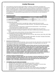
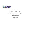
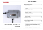
OPTION HDD KIT
SA-K51U
INSTRUCTIONS
R
For Customer Use:
Enter below the Serial No. which is
located on the body. Retain this
information for future reference.
VICTOR COMPANY OF JAPAN, LIMITED
is a registered trademark owned by VICTOR COMPANY OF JAPAN, LTD.
is a registered trademark in Japan, the U.S.A., the U.K. and many other countries.
© 2002 VICTOR COMPANY OF JAPAN, LIMITED
Model No.
Printed in Japan
LLT0020
SA-K51U
This instruction book is made from
100% recycled paper.
Serial No.
LLT0020
11. For added protection for this product during a lightning storm, or when it is left unattended
and unused for long periods of time, unplug it form the wall outlet and disconnect the
antenna or cable system. This will prevent damage to the product due to lightning and
power-line surges.
IMPORTANT SAFEGUARDS
1. Read all of these instructions.
2. Save these instructions for later use.
12. Do not allow anything to rest on the power cord. Do not locate this appliance where the
cord will be abused by persons walking on it.
3. All warnings on the product and in the operating instructions should be adhered to.
13. Follow all warnings and instructions marked on the appliance.
4. Unplug this appliance system from the wall outlet before cleaning. Do not use liquid cleaners or aerosol cleaners. Use a damp cloth for cleaning.
14. Do not overload wall outlets and extension cords as this can result in fire or electric shock.
5. Do not use attachments not recommended by the appliance manufacturer as they may
cause hazards.
15. Never push objects of any kind into this appliance through cabinet slots as they may touch
dangerous voltage points or short out parts that could result in a fire or electric shock.
Never spill liquid of any kind on the appliance.
6. Do not use this appliance near water - for example, near a bathtub,
washbowl, kitchen sink, or laundry tub, in a wet basement, or near a
swimming pool, etc.
16. Do not attempt to service this appliance yourself as opening or removing covers may
expose you to dangerous voltage or other hazards. Refer all servicing to qualified service
personnel.
PORTABLE CART WARNING
(symbol provided by RETAC)
7. Do not place this appliance on an unstable cart, stand, or table. The
appliance may fall, causing serious injury to a child or adult, and
serious damage to the appliance.
S3126A
Use only with a cart or stand recommended by the manufacturer, or
sold with the appliance. Wall or shelf mounting should follow the
manufacturer’s instructions, and should use a mounting kit approved by the manufacturer.
An appliance and cart combination should be moved with care.
Quick stops, excessive force, and uneven surfaces may cause the appliance and cart
combination to overturn.
8. Slots and openings in the cabinet and the back or bottom are pro-vided for ventilation, and
to insure reliable operation of the appliance and to protect it from overheating, these
openings must not be blocked or covered. The openings should never be blocked by
placing the appliance on a bed, sofa, rug, or other similar surface.
This appliance should never be placed near or over a radiator or heat register. This appliance should not be placed in a built-in installation such as a bookcase unless proper
ventilation is provided.
9. This appliance should be operated only from the type of power source indicated on the
marking label. If you are not sure of the type of power supplied to your home, consult your
dealer or local power company. For appliance designed to operate from battery power,
refer to the operating instructions.
17. Unplug this appliance from the wall outlet and refer servicing to qualified service personnel under the following conditions:
a. When the power cord or plug is damaged or frayed.
b. If liquid has been spilled into the appliance.
c. If the appliance has been exposed to rain or water.
d. If the appliance does not operate normally by following the operating instructions. Adjust only those controls that are covered by the operating instructions as improper
adjustment of other controls may result in damage and will often require extensive
work by a qualified technician to restore the appliance to normal operation.
e. If the appliance has been dropped or the cabinet has been damaged.
f. When the appliance exhibits a distinct change in performance - this indicates a need
for service.
18. When replacement parts are required, be sure the service technician has used replacement parts specified by the manufacturer that have the same characteristics as the original part. Unauthorized substitutions may result in fire, electric shock, or other hazards.
19. Upon completion of any service or repairs to this appliance, ask the service technician to
perform routine safety checks to determine that the appliance is in safe operating condition.
10. This appliance system is equipped with a 3-wire grounding type plug (a plug having a
third (grounding) pin). This plug will only fit into a grounding-type power outlet. This is a
safety feature. If you are unable to insert the plug into the outlet, contact your electrician to
replace your obsolete outlet. Do not defeat the safety purpose of the grounding plug.
I
II
Safety Precautions
Thank you for purchasing this product.
(These instrustions are for SA-K51U)
Before beginning to operate this unit, please read the instruction manual carefully in
order to make sure that the best possible performance is obtained.
FOR USA AND CANADA
Due to design modifications, data given in this
instruction book are subject to possible change
without prior notice.
CAUTION
RISK OF ELECTRIC SHOCK
DO NOT OPEN
CAUTION:TO REDUCE THE RISK OF ELECTRIC
SHOCK. DO NOT REMOVE COVER (OR
BACK). NO USER-SERVICEABLE PARTS
INSIDE.REFER
SERVICING
TO
QUALIFIED SERVICE PERSONNEL.
The lightning flash wish arrowhead
symbol, within an equilateral triangle is
intended to alert the user to the presence
of uninsulated “dangerous voltage” within
the product’s enclosure that may be of
sufficient magnitude to constitute a risk
of electric shock to persons.
The exclamation point within an
equilateral triangle is intended to alert
the user to the presence of important
operating and maintenance (servicing)
instructions
in
the
literature
accompanying the appliance.
WARNING:
TO REDUCE THE RISK OF FIRE OR
ELECTRIC SHOCK, DO NOT EXPOSE
THIS APPLIANCE TO RAIN OR
MOISTURE.
AVERTISSEMENT:
POUR EVITER LES RISQUES
D’INCENDIE OU D’ELECTRO-CUTION,
NE PAS EXPOSER L’APPAREIL A
L’HUMIDITE OU A LA PLUIE.
Features
Attaching the expansion hard disk SA-K51U to the VR-510U increases the memory capacity
to 160 GB and makes long-time recording possible.
Precautions
● Ensure that the power to the VR-510U is off and the plug is removed from the power
socket before attaching the SA-K51U. Not doing so may result in a fire or electric shock.
● Do not touch the edge of the metal frame, as there is the risk of injury.
● Users must not attach the SA-K51U themselves because there is the risk of a burn from
an electric shock. Request your nearest JVC Service Center to perform the work. There
will be a charge for the work.
● Any data recorded on the original hard disk will be lost when the SA-K51U is attached.
INFORMATION (FOR CANADA)
This Class B digital apparatus complies with
Canadian ICES-003.
RENSEIGNEMENT (POUR CANADA)
Cet appareil numérique de la Class B est conforme
á la norme NMB-003 du Canada.
Information for USA
This device complies with part 15 of the FCC Rules.
Changes or modifications not approved by JVC could
void the user’s authority to operate the equipment.
2
3
3.
How to Attach
First, set the ID of the hard disk drive to “SLAVE.” Refer to the instructions on how to set the
ID shown on the top (side with the model-name label affixed) of the hard disk drive.
1.
Fix the SA-K51U in place by inserting the screws (black) into the four screw holes of the
stand and tightening them while the connector part of the SA-K51U is positioned so that
it is faces the rear panel of the VR-510U.
* Keep the screws straight and steady when tightening them because the stand has
non-threaded screw holes.
Fix the SA-K51U in place by inserting the screws (silver) into the four screw holes of the
stand and tightening them.
Stand
Fix in place so as the
flap and the hard disk
drive’s connectors are
on opposite sides.
Connector part
SA-K51U
2.
4.
Connect the hard disk power cable and flat cable to the connectors on the SA-K51U.
Open the cover of the VR-510U and remove the clamp from the power cable for the hard
disk.
Hard disk power cable
Flat cable
Clamp
Hard disk power cable
4
5
4.
How to Mount
The following describes how to operate the front panel of the VR-510U to mount the SAK51U.
1.
Insert the plug into the plug socket and switch on the power switch of the VR-510U.
3 - 1 0 - 0 2 SUN 1 8 : 0 3 : 3 8
AL - - - - - - - - - - %
MO U N T E R R O R
2.
The MENU screen is displayed.
[ F UNC T I ON - 1 ]
J . D I R– +
1 . F AC TORY S E T T I NG
OF F
2 . H D D MO U N T [ - - - - ]
OF F
3 . D I P SW - 0
OF F
4 . D I P SW - 1
OF F
5 . D I P SW - 2
OF F
6 . D I P SW - 3
OF F
7 . D I P SW - 4
OF F
8 . D I P SW - 5
OF F
9 . D I P SW - 6
OF F
1 0 . D I P SW - 7
OF F
5.
The jog operation switches from J.DIR ↑ ↓ to J.DIR – +.
Set to standard format (STD) or extended format (EXTN) by turning the jog dial.
[ F UNC T I ON - 1 ]
J . D I R– +
1 . F AC TORY S E T T I NG
OF F
2 . H D D MO U N T [ - - - - ]
STD
3 . D I P SW - 0
OF F
4 . D I P SW - 1
OF F
5 . D I P SW - 2
OF F
6 . D I P SW - 3
OF F
7 . D I P SW - 4
OF F
8 . D I P SW - 5
OF F
9 . D I P SW - 6
OF F
1 0 . D I P SW - 7
OF F
Turning the jog dial switches between OFF ↔ STD ↔ EXTN
↔ OFF in order.
Selects whether the hard disk is formatted with standard
or extended mode.
When the disk is formatted, all existing data on the hard
disk will be erased.
STD:
Normally, use this position. Up to 13,000 alarm/
sensor events can be recorded.
EXTN: Set to this position if you want to be able to record
more than 13,000 alarm/sensor events (up to about
100,000 events).
* Extended formatting takes about 5 minutes to complete.
Recording time is shorter than with the standard format.
6.
Make sure FUNCTION-1 is selected and then return the shuttle dial to the SELECT
position by turning it either clockwise or anticlockwise.
[ F UNC T I ON - 1 ]
J.DIR
1 . F AC TORY S E T T I NG
OF F
2 . H D D MO U N T [ - - - - ]
OF F
3 . D I P SW - 0
OF F
4 . D I P SW - 1
OF F
5 . D I P SW - 2
OF F
6 . D I P SW - 3
OF F
7 . D I P SW - 4
OF F
8 . D I P SW - 5
OF F
9 . D I P SW - 6
OF F
1 0 . D I P SW - 7
OF F
6
* It takes 10 to 20 seconds for the message to be displayed
after the power has been switched on.
* When the VR-510U is not receiving video input signals,
INPUT SIG ERROR and MOUNT ERROR messages are
displayed on the monitor alternatively.
Simultaneously press the MENU button and the 4 button while holding down the STOP
button.
[ MENU ]
J.DIR
F UNC T I ON - 1
F UNC T I ON - 2
HOUR ME T ER
EMERGENCY H I S TORY
O P E R A T I O N C H E C K MO D E
OPE
VER .
xx . xx
HDR
VER .
xx . xx
BOO T
VER .
xx . xx
SCS I
VER .
xx . xx
EXT . M VER .
xx . xx
3.
The MOUNT ERROR message is displayed on the monitor.
Select 2.HDD MOUNT by turning the jog dial and then return the shuttle dial to the
SELECT position by turning it either clockwise or anticlockwise.
Press the ¢ to start mounting.
3 - 1 0 - 0 2 SUN 1 8 : 0 5 : 2 1
AL - - - - - - - - - - %
The FUNCTION-1 screen is displayed.
MO U N T
x x%
I NPU T S I G ERROR
During mounting MOUNT XX% is displayed on the monitor.
Numbers are displayed instead of XX to show the progress.
When mounting has finished the INPUT SIG ERROR and
MOUNT ERROR messages are displayed on the monitor
alternately. After approximately 10 to 20 seconds the
MOUNT ERROR message disappears and mounting is
complete.
7
How to Verify Mounting
The following describes how to operate the front panel of the VR-510U to verify that the SAK51U is mounted.
1.
Press the MENU button.
[ MENU ]
J.DIR ·
C LOCK S E T
O N S C R E E N / F . D I S P MO D E
H D R MO D E
E X T MO D E
A L A RM / S E N S O R MO D E
BUZ Z ER
P ROGR AM T I ME R
HOR I DAY S E T
S Y S T EM / L I S T
2.
The MENU screen is displayed.
Specifications
● Mass:
Approx. 750 g (including stand)
● Power Consumption:
9 W or less
● Allowable operating temperature:
5°C to 40°C
● Allowable storage temperature:
–20°C to 60°C
● Allowable operating humidity:
30% to 80% RH
● Accessories:
Stand × 1
Screw (silver) × 4
Screw (black) × 4
Select SYSTEM/LIST by turning the jog dial and then return the shuttle dial to the SELECT
position by turning it either clockwise or anticlockwise.
[ S Y S T EM ]
UT I L I TY
J OG
·
[ 1 6 0 GB ]
The SYSTEM/LIST screen is displayed. Verify that 160 GB
is displayed for the UTILITY item.
[ L I ST ]
HOUR ME T ER /
P OW E R L O S S L I S T
8
9