1
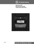
e
GE Zenith Controls
Product Bulletin
ZTS Series
Automatic Transfer Switches
Specification
Assistance
GE Zenith offers a complete
range of product guide
specifications to help you
determine your needs.
For more information,
please consult your local
GE Zenith representative,
our factory or our website
at www.geindustrial.com.
Since its introduction, the GE Zenith ZTS Series of
transfer switches has become a hallmark of quality
and performance. Reliability resulting from superior
design and heavy duty construction has made the
ZTS the industry standard for critical installations.
Our emphasis on research and development, design
improvements, materials, manufacturing methods,
quality assurance, and service yields products that have
been proven in hundreds of thousands of applications.
Subsequent to the first ZTS units installed, our engineering staff has been dedicated to the improvement
and expansion of our line. Today, GE Zenith offers the
widest selection of transfer switch products worldwide.
• ZTS Automatic Transfer Switches
40-4000 Amps
• ZTSD Delayed Transition Transfer Switches
40-4000 Amps
• ZTSCT Closed Transition Transfer Switches
100-4000 Amps
• ZBTS Automatic Transfer/Bypass Switches
100-4000 Amps
• ZBTSD Delayed Transition Bypass Switches
100-4000 Amps
• ZBTSCT Closed Transition Bypass Switches
100-4000 Amps
All ZTS products meet or exceed industry requirements
allowing specification and installation confidence.
• UL 1008 listed through 480 VAC
• CSA C22.2 No. 178 listed through 600 VAC
• IEC 947-6-1 listed through 480 VAC
• Codes and Standards
✓ NFPA 70, 99, 101, 110
✓ NEC 517, 700, 701, 702
✓
IEEE 446, 241
✓
NEMA ICS2-447
• Controls tested in accordance with:
✓ IEEE 472 (ANSI C37.90A)
✓ EN55022 Class B (CISPR 11)
(Exceeds EN55011 & MILSTD 461 Class 3)
✓ EN61000-4-2 (Level 4)
✓ EN61000-4-3 (ENV50140) 10 v/m
✓ EN61000-4-4
✓ EN61000-4-5, IEEE C62.41 (1.2 X 50ms, 5 & 8 kV)
✓ EN61000-4-6 (ENV50141)
✓ EN61000-4-11
• Enclosures meet the requirements of:
✓ UL 508, 50
✓ ANSI C33.76
✓ ICS 6
✓ NEMA 250
• Quality System:
✓ ISO 9001 Registered
PB-5066 (6/04)
ZTS Series
Automatic Transfer Switches
Electrical Ratings
• Ratings 40 to 4000 amperes
• 2, 3 or 4 Poles
• Open type, NEMA 1,
3R, 4, 4X and 12
• Available to 600 VAC,
50 or 60 Hz
• Suitable for emergency and
standby applications on
all classes of load, 100%
tungsten rated through
400 amps
• UL 1008 listed at 480 VAC
• CSA C22.2 No. 178
certified at 600 VAC
• IEC 947-6-1 listed at 480 VAC
Performance Features
• Contact transfer speed
less than 100 milliseconds
• High close-in and
withstand capability
• Temperature rise test per
UL 1008 conducted after
overload and endurance
tests - exceeds UL
requirements
• Available in ZTS (utilitygenerator), ZTSU (utilityutility), ZTSG (generatorgenerator) and ZTSM
(manual) configurations
Design and
Construction Features
• Double throw,
interlocked operation
• Electrically operated,
mechanically held by a
simple, over-center
mechanism
• Segmented silver tungsten
alloy contacts with
separate arcing contacts
on 225 amp and above
• Arc quenching grids,
enclosed arc chambers,
and wide contact air gap
for superior source-tosource isolation on all units
• Control circuit disconnect
plug and drive inhibit
switch for safe maintenance
• Components accessible
for inspection and
maintenance without
removal of the switch
or power conductors
• Mechanical indicator and
contact chamber cover
designed for inspection,
safety and position
designation
PB-5066 • Page 2
The ZTS Series is the building block
of our transfer switch product line.
This ruggedly built power contactor
family of switches has been specifically
designed for transfer switch duty with
dependability, versatility and user
friendliness of prime concern.
ZTS switches are available in open type construction
for switchboard installation or NEMA enclosed to
the customer’s specifications. The power panel
components, consisting of power switching contacts,
drive mechanism and terminal lugs, are mounted
on a specially formed panel. Logic devices including
microprocessor control auxiliary time delays and
special accessory equipment are assembled on the
door for ease of maintenance and separation from the
power section. They are connected with a numbered
wiring harness equipped with a disconnect plug that
allows isolation of the control panel for maintenance.
ZTS Series Method of Operation
When the normal source voltage fails or drops to a
predetermined point (usually 80% of nominal), if
required, a circuit is closed to start the engine
generator set. When the emergency source reaches
90% of rated voltage and 95% of rated frequency, the
drive solenoid is energized through the emergency
coil control relay, causing the main contacts to
disconnect the load from the normal source and
connect it to the emergency source. After the drive
solenoid has completed its electrical stroke and is
seated, the emergency coil control relay opens to
disconnect it. The transfer switch is now mechanically
locked in the emergency position.
When normal voltage is restored to a predetermined
point (usually 90% of nominal), the control voltage
sensing energizes. The normal side coil relay closes,
and after the drive solenoid has completed its electrical
stroke and is seated, the coil control relay opens to
disconnect it. The transfer switch is now mechanically
locked in the normal position.
Drive Mechanism
All GE Zenith ZTS switches employ the simple “overcenter” principle to achieve a mechanically locked
position in either normal or emergency and GE Zenith’s
high speed drive assures contact transfer in 100 ms
or less. High contact pressure and positive mechanical
lock allow for high withstand and closing ratings, far
exceeding UL requirements. All ZTS units are listed with
UL umbrella breaker, severe breaker and current
limiting fuse ratings.
Neutral Switching
The GE Zenith ZTS Series is available in true four pole
designs for multi-source power systems that require
neutral switching. The neutral contact is on the same
shaft as the associated main contacts. This ensures
positive operation, and avoids any possibility that
the neutral contact will fail to open or close, as is
possible when the neutral pole is an add-on accessory.
The neutral contacts are identical to the main contacts,
having the same current carrying and high withstand/
closing ratings as the mains. They are designed to
break last and make first to reduce the possibility of
transients while switching the neutral.
Safe Manual Operation
The ZTS manual operator consists of a large, easy-to-use
handle that fits securely for manual operation during
installation and maintenance or in an emergency.
The ZTS may be provided with an operator inhibit
switch to disconnect the electrical drive prior to
maintenance. Fully enclosed wrap-around arc covers
shield the main contacts and mechanical components,
preventing operator exposure during manual operation.
Transferring Large Motor
or Highly Inductive Loads
Some loads, especially large motors, receive severe
mechanical stress if power is trans-ferred out of phase
while the motor is still rotating. Also, back EMF generated by a motor may result in excess currents that
can blow fuses or trip circuit breakers. GE Zenith
offers four solutions to these problems:
1. Universal Motor
Disconnect (UMD): This load
control disconnects a large
motor via its control circuit
for an adjustable period of
time prior to transfer in either
direction. For switching multiple
motors, GE Zenith Accessory A62
disconnects the motors prior to
transfer and brings them back
on line sequentially.
2. Accessory R50: This is an
in-phase monitor that compares
the phase angle between both
sources of power and prevents
transfer until the two are approximately in phase (within a self
adjusting range). GE Zenith’s
high speed transfer action
coupled with the MX series
microprocessor control logic
ensure closures at or near
zero degree phase difference.
3. Series ZTSD: GE Zenith
offers delayed transition
switching on transfer switches
rated 40 amperes and above –
the GE Zenith ZTSD Series. This
programmed center-off position
allows for the full decay of
rotating motors or transformer
fields. It can also be used for
load shedding of selected
circuits or other appli-cations
which require a means to
disconnect the load from either
source. Major UPS system manufacturers recommend delayed
transition switches for proper
restart sequencing of their systems.
4. Series ZTSCT: GE Zenith’s
series of closed transition switches
combine ZTSD operation during
a source failure with a highly
engineered control system that
allows momentary paralleling
(100 ms) of two acceptable
sources, thereby limiting the
impact of transfer on the load.
MX250 series
Microprocessor Controller
LOAD DISCONNECT TD
PRE XFR
TIME REMAINING 04:02
MOR E
Entelli-Switch 250
LEDs are used in a recognizable line configuration
for continuous monitoring of switch position. A new
LCD display shows source availability, exercise time
delay operation and system source condition. A new
simplified adjustment is featured for voltage, frequency
and time delay settings.
The control operates off a close differential 3
phase under-voltage sensing of source 1, factory
standard setting 90% pickup, 80% dropout; underfrequency sensing of source 1 factory setting 95%
pickup; voltage and frequency sensing of source 2,
factory standard setting 90% pickup voltage, 95%
pickup frequency. All factory settings are operator
adjustable (see table below).
A test is standard (fast test/load/no load) to
simulate source 1 failure - automatically bypassed
should source 2 fail.
Performance Features
• UL, CSA and IEC listed
• Ringing wave immunity per IEEE 472 (ANSI C37.90A)
• Condusted and Radiated Emissions per EN55022 Class B
(CISPR 11) (Exceeds EN55011 & MILSTD 461 Class 3)
• ESD Immunity test per EN61000-4-2 (Level 4)
• Radiated RF, electromagnetic field immunity test
per EN61000-4-3 (ENV50140) 10v/m
• Electrical fast transient/burst immunity test
for EN61000-4-4
• Surge immunity test per EN61000-4-5 IEEE C62.41
(1.2 x 50ms, 5 & 8 kV)
• Conducted immunity test per EN61000-4-6 (ENV50141)
• Voltage dips and interruption immunity EN61000-4-11
Technical Benefits
• Separate line voltage components for controller isolation
• Inputs optoisolated for high electrical immunity to transients and noise
• Built-in electrical operator protection
More Enhanced Features
• Available in ALL transfer modes:
~ Open, Delayed & Bypass
~ Closed (with newly integrated transition control)
• Simplified maintenance – major components are easily replaceable
• Close differential under-voltage sensing of the normal source
• Voltage and frequency sensing of the emergency source
(all settings are adjustable)
• User-friendly programmable engine exerciser,
used for the engine generator with or without
load, at ANY interval in a one-year period
• Operating voltages available in a single
controller for most domestic and international
applications
• Real-time display of ATS status, including
active timer(s)
• Multiple levels of user-defined password
protection
• Serial communications allowing connectivity
with other ATS's, paralleling switchgear, and
SCADA systems
• Time-tested synchronous logic automatically
measures phase angle and frequency allowing
disturbance-free transfer
• Unsurpassed statistical ATS/System monitoring
available in real-time
• T3/W3 elevator pre-signal. Automatically
bypassed if the selected source fails, minimizing
time an elevator is without power
• Universal Motor Disconnect (UMD) sends
a pre-signal, post-signal or both to any motor
control center. Not bypassed in an outage,
the UMD ensures safety in the event of a
single phase loss
• Voltage unbalance detection standard
• Extensive 2/5/10 Warranty
Page 3 • PB-5066
ZTS Series
Accessory Group Matrix
Accessories
MSTDS
MEXES
Group Packages
MCONS MSENS
MSPES
MPSGS
6P
A1
A1E
A3
2
2
2
2
3
A4
2
2
2
2
3
2
2
2
2
2
2
2
2
2
2
2
2
Calibrate
CDT
CDP
**DS
*DT
*DW
E
EL/P
K/P
L1
L2
L3
L4
*LN
P1
Q2
Q3
Q7
R1-1
R1-3
R15
*R15D
R16
R50
S5P
S12P
S13P
T
T3/W3
U
UMD
VI
W
YEN
2 2
3
Standard Accessory included in the group package.
Optional Accessory not included but can be added to group package.
Optional Accessory. Can not be used with accessory having the same symbol.
N/A
Denotes an Accessory with 2 circuits as a standard.
Denotes an Accessory with 3 circuits as a standard.
PB-5066 • Page 4
Transition Units Only.
* Delayed
Optional for 40-400 Amp
**
ZTS Series
Accessory Definitions
6P
Microprocessor activated test switch (Momentary)
6A
Hardwired test switch (Maintained)
6AP
Microprocessor activated test switch (Maintained)
6B
Hardwired test switch (Maintained Auto Momentary Test) Key operated
6C
Hardwired test switch (Maintained Auto Maintained Test) Key operated
A1
Auxiliary Contact S.P.D.T. - Normal (Source 1)
Failure
CTAP
Chicago transfer alarm panel mounted in door of
enclosure. Includes 3 aux. contacts and fuse.
DS
Disconnect Switch. Disconnects source voltage
to transfer power panel
DT (Delayed Transition Only)
Time Delay from Neutral Switch position
to Source 1 on retransfer
DW (Delayed Transition Only)
Time Delay from Neutral Switch position
to Source 2 on retransfer
E
Engine Start Relay
EL/P
Event log of last 16 events
A1E
Auxiliary Contact S.P.D.T. - Emergency (Source 2)
Failure
F
Fan contact, closed when engine runs.
A3
Auxiliary Contact - closed in emergency (source 2)
Additional available (10 max.) on ZTS and need
to be specified
HT(1)(2)
Heater and Thermostat 208/240V (1)
380/600V (2) mounted and interwired in
enclosure. (requires larger enclosure for 40-200A)
A4
Auxiliary Contact - closed in normal (source 1)
Additional available (10 max.) on ZTS and
need to be specified
K
Frequency Meter - Door mounted
A62
Motor disconnect and staged restart (1 contact)
AB3
Auxiliary Contact - closed in bypass emergency
(source 2) (S.P.D.T.) (Standard up to 400A)
Additional available (10 max.) on ZTS and need
to be specified
K/P
Frequency Indication on the controller
L
LNP Center-off position LCD-Indicator
Indicating LED lights:
L1 Indicates Switch in Source 2 position.
L2 Indicates Switch in Source 1 position.
L3 Indicates Source 1 available.
L4 Indicates Source 2 available.
AB4
Auxiliary Contact - closed in bypass normal
(source 1) (S.P.D.T.) (Standard up to 400A)
Additional available (10 max.) on ZTS and
need to be specified
M1
Single Phase Amp Meter
B9
Battery charger (ships separate from ATS)- semifloat 5 amp (need to specify input/output voltage
and type LA, N, FL)
M80
Digital Meter Measures and displays true RMS volts,
amps and frequency in a three-phase power system.
M2
Three Phase Amp Meter
Calibrate
Microprocessor activated calibration feature
M82
Digital Meter Includes M80 functions plus Watts,
KVA, KVAR, PF, etc. w/Modbus RS485 port
CDP
Programmable exerciser daily, 7/14/28/365 days
user-selectable, with or without load.
M83
Digital Meter Includes M82 functions plus
THD capability and Modbus RS485 port
CDT
Exerciser no load timer. Increased functionality no
longer requires a jumper.
M84
Digital Meter Includes M83 functions plus
unbalance 128 samples/cycle data logging,
waveform capture and sag/swell capture.
Page 5 • PB-5066
ZTS Series
Accessory Definitions
M85
Digital Meter Includes M84 functions plus
unbalance 256 samples/cycle data logging,
waveform capture and sag/swell capture.
M86
Digital Meter Includes M85 functions plus
large graphical screen display with Ethernet
communications port.
N1
Running Time Indicator - Door mounted
N2
Operation Counter - Door Mounted
P1
Engine Start Timer (adjustable to 6 sec.)
P2
Engine Start Timer (adjustable to 300 sec.)
Q2
Peak shave/remote load test/area protection Relay (S.P.D.T.) (Need to specify voltage - 120 VAC,
24 VAC, 24 VDC - 120V default standard)
Q3
Inhibit transfer to emergency (Source 2) (load add
relay) - Relay (S.P.D.T.) (Need to specify voltage 120 VAC, 24 VAC, 24 VDC - 120V default standard)
Q7
Inhibit transfer to normal (Source 1) - Relay
(S.P.D.T.) (Need to specify voltage - 120 VAC, 24
VAC, 24 VDC - 120V default standard)
S12P
Microprocessor activated auto/manual retransfer
selector switch for trnsferring to Normal
(Source 1) (includes microprocessor activated
YN & YE accessory)
S13P
Microprocessor activated commit/no commit
on transferring to Emergency (Source 2)
(with enable/disable)
S14
Keyed selector switch for
(retransfer to normal-test-auto)
SW1
Auto/Off/Start Engine control selector Door mounted (keyed or non-keyed
operation available)
SW2
Auto/Off Engine control selector - Door mounted
(keyed or non-keyed operation available)
SW3
Source Priority Selector Switch - Door mounted
Allows selection of Source 1 or Source 2 to be
the Prime Source. Transfer Switch will transfer to
selected Prime Source if that Source is available.
(keyed or non-keyed operation available)
T
Retransfer to normal adjustable time delay
T3/W3
Pre-signal contact on transfer to Normal (Source 1)
or Emergency (Source 2) during test.
R1-1/R1-3
Over Voltage sensing for normal (Source 1)
single (R1-1) or three (R1-3) phase
U
Engine stop /cool adjustable cool down timer
R15/R15D
Load Shed. Should Source 2 become overloaded,
a signal can be given to switch to the dead
or Mid position.
UMD
Pre and ppost transfer output adjustable time range.
Functions in both directions. Includes 2 circuits.
Additional circuits available.
R16
Phase rotation sensing of Normal (Source 1) and
Emergency (Source 2)
VI
Voltage imbalance between phases (3 Phase only)
R26/R26D
Interruptable Power Rate Provisions.
Allow transfer out of Source 1 position to Mid
position or dead Source 2. Alarm and Pre-Signal
circuit included. (Need to specify voltage - 120 VAC,
24 VAC, 24 VDC - 120V default standard)
R50
In Phase monitor between Normal (Source 1) and
Emergency (Source 2) to allow transfer
W
Adjustabvle time delay on transfer to Emergency
(Source 2)
YEN
Bypass transfer timers function (soft switch in control)
ZNET
Microprocessor Communication Module
S5P
Microprocessor activated auto/manual retransfer
selector switch for trnsferring to Normal (Source 1)
(includes microprocessor activated YN accessory)
PB-5066 • Page 6
ZTS Series
Withstand Ratings
GE Zenith ZTS Series Automatic Transfer Switches have been subjected to an extensive test program to show that they comply with and exceed UL 1008 standards,
as well as the various performance specifications used by most government agencies and major electrical engineering firms throughout the world. The primary test to
ensure the quality and dependability of an automatic transfer switch is its ability to close into and withstand high fault currents. The table shows the Underwriters
Laboratories and Canadian Standards certified withstand and closing current ratings in symmetrical RMS amperes at 480 and 600 volts AC.
GE Zenith ZTS Switches
Rated for Total Systems or Motor Loads (1)
Withstand and Closing Current Ratings per UL 1008 and CSA
Specific Coordinated
Breaker Rating (3)
Current Limiting Fuse
GE Zenith
Model No.
UL 1008
ZTS Switch
Rating
Any Molded Case
Breaker Rating
Maximum
Fuse Size
Amps
Maximum
Circuit Amps
at 480 VAC
(UL)
Maximum
Circuit Amps
at 600 VAC
(CSA)
Maximum
Circuit
Breaker
Size Amps
Maximum
Circuit Amps
at 480 VAC
(UL)
Maximum
Circuit Amps
at 600 VAC
(CSA)
Maximum
Circuit Amps
at 480 VAC (UL)
Maximum
Circuit Amps
at 600 VAC (CSA)
ZTS4 (2)
40
50
200,000
200,000
400
30,000
22,000
10,000
10,000
ZTS8 (2)
80
100
200,000
200,000
400
30,000
22,000
10,000
10,000
ZTS10 (2)
100
125
200,000
200,000
400
30,000
22,000
10,000
10,000
ZTS15 (2)
150
200
200,000
200,000
400
30,000
22,000
10,000
10,000
ZTS22 (2)
225
300
200,000
200,000
800
50,000
42,000
35,000
35,000
ZTS26 (2)
260
350
200,000
200,000
800
50,000
42,000
35,000
35,000
ZTS40 (2)
400
600
200,000
200,000
800
50,000
42,000
35,000
35,000
ZTS60
600
750
200,000
150,000
800
65,000
50,000
50,000
42,000
ZTS80
800
1000
200,000
150,000
1600
65,000
50,000
50,000
42,000
ZTS100
1000
1250
200,000
150,000
1600
85,000
65,000
50,000
42,000
ZTS120
1200
1500
200,000
150,000
1600
85,000
65,000
50,000
42,000
ZTS160
1600
2000
200,000
150,000
2500
100,000
85,000
100,000
85,000
ZTS200
2000
2500
200,000
150,000
2500
100,000
85,000
100,000
85,000
ZTS300
3000
4000
200,000
150,000
4000
100,000
85,000
100,000
85,000
ZTS400
4000
6000
200,000
150,000
5000
100,000
85,000
100,000
85,000
ZBTS10 (2)
100
125
200,000
200,000
800
50,000
42,000
35,000
35,000
ZBTS15 (2)
150
200
200,000
200,000
800
50,000
42,000
35,000
35,000
ZBTS22 (2)
225
300
200,000
200,000
800
50,000
42,000
35,000
35,000
ZBTS26 (2)
260
350
200,000
200,000
800
50,000
42,000
35,000
35,000
ZBTS40 (2)
400
600
200,000
200,000
800
50,000
42,000
35,000
35,000
ZBTS60
600
750
200,000
150,000
800
65,000
50,000
50,000
42,000
ZBTS80
800
1000
200,000
150,000
1600
85,000
65,000
50,000
42,000
ZBTS100
1000
1250
200,000
150,000
1600
85,000
65,000
50,000
42,000
ZBTS120
1200
1500
200,000
150,000
1600
85,000
65,000
50,000
42,000
ZBTS160
1600
2000
200,000
150,000
2500
100,000
85,000
100,000
85,000
ZBTS200
2000
2500
200,000
150,000
2500
100,000
85,000
100,000
85,000
ZBTS300
3000
4000
200,000
150,000
4000
100,000
85,000
100,000
85,000
ZBTS400
4000
6000
200,000
150,000
5000
100,000
85,000
100,000
85,000
ZTSD4 (2)
40
50
200,000
200,000
800
50,000
42,000
35,000
35,000
ZTSD8 (2)
80
100
200,000
200,000
800
50,000
42,000
35,000
35,000
ZTSD10 (2)
100
125
200,000
200,000
800
50,000
42,000
35,000
35,000
ZTSD15 (2)
150
200
200,000
200,000
800
50,000
42,000
35,000
35,000
ZTSD22 (2)
225
300
200,000
200,000
800
50,000
42,000
35,000
35,000
ZTSD26 (2)
260
350
200,000
200,000
800
50,000
42,000
35,000
35,000
ZTSD40 (2)
400
600
200,000
200,000
800
50,000
42,000
35,000
35,000
ZTSD60 (2)
600
750
200,000
200,000
800
65,000
50,000
50,000
42,000
ZTSD80 (2)
800
1000
200,000
N/A
1200
65,000
N/A
50,000
N/A
ZTSD100 (2)
1000
1250
200,000
200,000
1600
85,000
65,000
50,000
42,000
ZTSD120 (2)
1200
1500
200,000
200,000
1600
85,000
65,000
50,000
42,000
1. For each rating attained in above table, the heat run was
performed after the overload and endurance tests.
2. These models also listed for 100% tungsten lamp loads.
3. Consult factory for coordinated breaker types and ratings.
Page 7 • PB-5066
4. All transfer switches are rated in coordination with the protective
device installed. Lower rated devices than those shown may be
utilized and the system rated accordingly.
5. Consult the factory for IEC ratings.
ZTS Series
Withstand Ratings
GE Zenith ZTS Switches
Rated for Total Systems or Motor Loads (1)
Withstand and Closing Current Ratings per UL 1008 and CSA
Specific Coordinated
Breaker Rating (3)
Current Limiting Fuse
GE Zenith
Model No.
UL 1008
ZTS Switch
Any Molded Case
Breaker Rating
Rating
Maximum
Fuse Size
Amps
Maximum
Circuit Amps
at 480 VAC
(UL)
Maximum
Circuit Amps
at 600 VAC
(CSA)
Maximum
Circuit
Breaker
Size Amps
Maximum
Circuit Amps
at 480 VAC
(UL)
Maximum
Circuit Amps
at 600 VAC
(CSA)
ZTSD160 (2)
1600
2000
200,000
200,000
2500
100,000
ZTSD200 (2)
2000
2500
200,000
200,000
2500
100,000
ZTSD300 (2)
3000
4000
200,000
200,000
4000
ZTSD400 (2)
4000
6000
200,000
200,000
ZTSCT10 (2)
100
750
200,000
ZTSCT15 (2)
150
750
200,000
ZTSCT22 (2)
220
750
ZTSCT26 (2)
260
ZTSCT40 (2)
Maximum
Circuit Amps
at 480 VAC (UL)
Maximum
Circuit Amps
at 600 VAC (CSA)
85,000
100,000
85,000
85,000
100,000
85,000
100,000
85,000
100,000
85,000
5000
100,000
85,000
100,000
85,000
150,000
800
65,000
50,000
50,000
42,000
150,000
800
65,000
50,000
50,000
42,000
200,000
150,000
800
65,000
50,000
50,000
42,000
750
200,000
150,000
800
65,000
50,000
50,000
42,000
400
750
200,000
150,000
800
65,000
50,000
50,000
42,000
ZTSCT60
600
750
200,000
150,000
800
65,000
50,000
50,000
42,000
ZTSCT80
800
1000
200,000
N/A
1200
65,000
N/A
50,000
N/A
ZTSCT100
1000
1250
200,000
150,000
1600
85,000
65,000
50,000
42,000
ZTSCT120
1200
1500
200,000
150,000
1600
85,000
65,000
50,000
42,000
ZTSCT160
1600
2000
200,000
150,000
2500
100,000
85,000
100,000
85,000
ZTSCT200
2000
2500
200,000
150,000
2500
100,000
85,000
100,000
85,000
ZTSCT300
3000
4000
200,000
150,000
4000
100,000
85,000
100,000
85,000
ZTSCT400
4000
6000
200,000
150,000
5000
100,000
85,000
100,000
85,000
ZBTSD10 (2)
100
125
200,000
200,000
800
50,000
42,000
35,000
35,000
ZBTSD15 (2)
150
200
200,000
200,000
800
50,000
42,000
35,000
35,000
ZBTSD22 (2)
225
300
200,000
200,000
800
50,000
42,000
35,000
35,000
ZBTSD26 (2)
260
350
200,000
200,000
800
50,000
42,000
35,000
35,000
ZBTSD40 (2)
400
600
200,000
200,000
800
50,000
42,000
35,000
35,000
ZBTSD60
600
750
200,000
150,000
800
65,000
50,000
50,000
42,000
ZBTSD80
800
1000
200,000
150,000
1600
85,000
65,000
50,000
42,000
ZBTSD100
1000
1250
200,000
150,000
1600
85,000
65,000
50,000
42,000
ZBTSD120
1200
1500
200,000
150,000
1600
85,000
65,000
50,000
42,000
ZBTSD160
1600
2000
200,000
150,000
2500
100,000
85,000
100,000
85,000
ZBTSD200
2000
2500
200,000
150,000
2500
100,000
85,000
100,000
85,000
ZBTSD300
3000
4000
200,000
150,000
4000
100,000
85,000
100,000
85,000
ZBTSD400
4000
6000
200,000
150,000
5000
100,000
85,000
100,000
85,000
ZBTSCT10 (2)
ZBTSCT15 (2)
100
150
750
200,000
150,000
800
65,000
50,000
50,000
42,000
750
200,000
150,000
800
65,000
50,000
50,000
42,000
ZBTSCT22 (2)
225
ZBTSCT26 (2)
260
750
750
200,000
200,000
150,000
150,000
800
800
65,000
65,000
50,000
50,000
50,000
50,000
42,000
42,000
ZBTSCT40 (2)
400
750
200,000
150,000
800
65,000
50,000
50,000
42,000
ZBTSCT60
600
750
200,000
150,000
800
65,000
50,000
50,000
42,000
ZBTSCT80
800
1000
200,000
150,000
1600
85,000
65,000
50,000
42,000
ZBTSCT100
1000
1250
200,000
150,000
1600
85,000
65,000
50,000
42,000
ZBTSCT120
1200
1500
200,000
150,000
1600
85,000
65,000
50,000
42,000
ZBTSCT160
1600
2000
200,000
150,000
2500
100,000
85,000
100,000
85,000
ZBTSCT200
2000
2500
200,000
150,000
2500
100,000
85,000
100,000
85,000
ZBTSCT300
3000
4000
200,000
150,000
4000
100,000
85,000
100,000
85,000
ZBTSCT400
4000
6000
200,000
150,000
5000
100,000
85,000
100,000
85,000
PB-5066 • Page 8
ZTS Series
Dimensional Specifications / Power Connection Terminals
ZTS Model Transfer Switches
NEMA 1 Enclosed
Weight
Ampere
Rating
Poles
Height
(A)
Width
(B)
Depth
(C)
Reference
Figure
Open
Type
NEMA 1
40, 80
100, 150
2, 3
4
24 (61)
24 (61)
18 (46)
18 (46)
11.13 (28)
11.13 (28)
A
A
21 (10)
24 (11)
57 (26)
60 (27)
1–7
225
260, 400
2, 3
4
46 (117)
46 (117)
24 (61)
24 (61)
14.13 (36)
14.13 (36)
A
A
70 (32)
75 (34)
165 (75)
170 (68)
1–7
600
2, 3
4
66 (168)
74 (188)
24 (61)
30 (76)
19.75 (50)
19.75 (50)
B
B
165 (75)
185 (84)
380 (172)
430 (195)
1–8
800, 1000, 1200
2, 3
4
74 (188)
74 (188)
30 (76)
40 (102)
19.75 (50)
19.75 (50)
B
B
190 (86)
210 (95)
455 (206)
540 (245)
1–8
1600
2000
3
4
90 (229)
90 (229)
30 (76)
36 (91)
48 (122)
48 (122)
C
C
345 (156)
450 (204)
1010 (458)
1160 (526)
1–8
3000
3
4
90 (229)
90 (229)
30 (76)
36 (91)
48 (122)
48 (122)
C
C
465 (211)
670 (304)
1130 (513)
1395 (633)
1 – 10
4000
3
4
90 (229)
90 (229)
40 (102)
46.5 (118)
60 (152)
60 (152)
C
C
770 (349)
1025 (465)
1595 (723)
1850 (839)
1 – 10
Application Notes
Application Notes:
1.
Metric dimensions (cm) and weights (Kg) shown in parenthesis adjacent
to English measurements in inches and pounds.
2. Includes 1.25" door projection beyond base depth. Allow a minimum of 3"
additional depth for projection of handle, light, switches, pushbuttons, etc.
3. All dimensions and weights are approximate and subject to change
without notice.
4. Special enclosures (NEMA 3R, 4, 12, etc.) dimensions and layout may differ.
Consult the GE Zenith factory for details.
5. Normal and emergency may be ordered inverted on any switch.
The load may be inverted 600-1200 amps. Consult the factory for details.
6. Special lug arrangements may require different enclosure dimensions.
For certified drawings, contact the GE Zenith factory.
7. Packing materials must be added to weights shown. Allow 15% additional
weight for cartons, skids, crates, etc.
8. Add 4" in height for removable lifting lugs.
9. Lug adapters for 3000-4000 amp limits may be staggered length for ease
of entrance. Consult the GE Zenith factory for details.
10. Ventilation louvers on both sides of enclosure at 3000 and 4000 amps.
One must be clear for airflow with standard cable connections.
C
A
Normal,
Emergency,
& Load Terminals
Cables/
Wire
Pole
Ranges
40-150
1
225
1
260
1
400
1
600
2
Switch
Size
Amps
#8 to 3/0 800/1000
AWG
/1200
#4 AWG to
1600
600 MCM
#4 AWG to
2000
600 MCM
#4 AWG to
3000
600 MCM
#2 AWG to
4000
600MCM
Normal
Emergency,
& Load Terminals
Cables/
Wire
Pole
Ranges
4
#2 AWG to
600 MCM
B
A
Figure A
Figure B
Figure C
AL-CU UL Listed Solderless
Screw-Type Terminals for
External Power Connections
Switch
Size
Amps
C
B
Notes:
*
Line and load terminals are located in rear and arranged for bus bar connection.
Terminal lugs are available at additional cost. Contact factory for more details.
1. Special terminal lugs and neutral bars are available at additional cost. Contact factory and advise cable sizes
and number of conductors per pole.
2. Fully rated neutral provided on 3 phase, 4 wire system.
*
3. Normal and emergency may be ordered inverted on any switch. Load may be inverted 600-1200 amps. Consult the factory for details. es:
4. Lug adapters for 3000-4000 amp units may be staggered length for ease of entrance. Consult the factory for details.
5. Special lug arrangements may require different enclosure dimensions. For certified drawings, contact the GE Zenith factory.
Page 9 • PB-5066
ZTS Series
Ordering Information
Z
B 0
Model/Type
Control
Panel
Config.
Ampere
Size
Switched
Poles
Enclosure
Type
Operational
Voltage
Z T S 0 0 0
B 0
0
0 0 4
B
N 0 1
A B
Standard (Open Transition)
Entelli-Switch 250
Microprocessor
Control Unit
Utility - Generator
40 amps
2 Poles
Type 1 Enclosed
Consult Table Below
E
N 1 2
3 Poles
Type 12 Enclosure
F
N 3 R
4 Poles
Type 3R Enclosure
Z T S D 0 0
Delayed Transition
Z T S C T 0
Closed Transition
U
Utility - Utility
M
Manual
Z B T S 0 0
Standard (Open Transition) w/ Bypass
Z B T S D 0
Delayed Transition w/ Bypass
0 0 8
80 amps
0 1 0
100 amps
0 1 5
150 amps
N 0 4
0 2 0
Type 4 Enclosure
200 amps
N 4 X
0 2 2
Z B T S C T
0 2 6
Closed Transition w/ Bypass
260 amps
M S T D
S
M E X E
S
M C O N
S
M S E N S
Type 4X Enclosure
225 amps
Accessories
M S P E
S
M P S G
S
Then choose
additional
accessories
X 0 0
Open Style Unit
0 3 0
300 amps
Switch Types
0 4 0
• Standard: Unless otherwise noted, the standard
switch with quick transfer will be supplied.
0 6 0
• Delayed Transition: When ordered as the ZTSD,
the delayed transition switch offers time delay during
transfer from one position to the other. This is primarily
for transfer of large motor or inductive loads.
0 8 0
• Closed Transition: When ordered as the ZTSCT,
the closed transition switch offers two basic modes
of operation. During a failure of one source or an out
of specification condition, the ZTSCT Model operates
as a standard delayed transition switch (ZTSD Model).
This sequence allows clear separation of an unreliable
source from an available one.
• Bypass: When ordered as the ZBTS, the bypass
transition switch offers a draw-out mechanism, with
electrical and mechanical interlocks for secure removal
after load bypass. In this way the transfer switch
and/or the control panel may be tested, isolated and
removed for maintenance without load interruption.
400 amps
600 amps
800 amps
1
0
0
1000 amps
1
2
0
1200 amps
1
6
0
1600 amps
2
0
0
2000 amps
2
6
0
2600 amps
3
0
0
3000 amps
4
0
0
4000 amps
Example
ZTSCT0B0040F-N0140STD
This number string shows the correct format for a ZTS Model Automatic Transfer Switch with closed transition,
an Entelli-Switch 250 microprocessor control unit, Utility - Generator, 400 amps, 4 pole, NEMA Type 1 enclosure,
120/208V 3Ø, 4 wire, 60 Hz system with the standard group of accessories.
g
A
B
Voltage
Phase
Config.
Hz
1
2
2
3
3
3
3
3
3
3
4
4
4
5
5
5
5
5
5
6
6
7
7
7
7
8
8
9
9
9
9
9
0
0
1
0
1
2
3
4
5
8
0
1
2
0
1
2
5
7
8
0
1
0
1
4
5
0
2
0
1
2
3
7
120
120/240
120/208
240
208
220
120/240
110/220
139/240
120/240
120/208
127/220
127/220
480
440
440
460
480
254/440
575
347/600
277/480
277
266/460
460
120/240
380
240/416
220/380
220/380
240/416
380
1
1
3
3
3
3
3
3
3
3
3
3
3
3
3
3
1
1
3
3
3
3
1
3
3
2
1
3
3
3
3
3
2 wire
3 wire
3 wire
3 wire
3 wire
3 wire
4 wire
4 wire
4 wire
4 wire
4 wire
4 wire
4 wire
3 wire
3 wire
3 wire
3 wire
2 wire
4 wire
3 wire
4 wire
4 wire
2 wire
4 wire
3 wire
4/5 wire
2 wire
4 wire
4 wire
4 wire
4 wire
3 wire
60
60
60
60
60
50
50
60
60
60
60
60
50
60
60
50
50
60
60
60
60
60
60
60
60
60
50
60
60
50
50
60
Note: Operating voltage must be specified at time of order.
Only the most common voltages are shown above.
GE Zenith Controls
A Product of GE Industrial Systems
General Electric Company
830 West 40 th Street, Chicago, IL 60609 USA
773 299-6600, Fax: 630 850-6899
www.geindustrial.com
Contents contained in this document are subject to
change without notice. Contact GE to verify details.