1
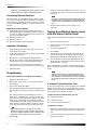
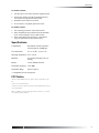
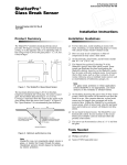
ITI Part No. 60-670-95R ,7,6$:'RRU:LQGRZ 6HQVRU Document Number: 466-1559 Rev. B March 2002 Installation Instructions Product Summary Door/Window Sensors can be installed on doors, windows, or many other objects that open and close. The sensors transmit signals to the Control Panel when a magnet mounted near the sensor is moved away from or closer to the sensor. Sensor Magnet Installation Guidelines Use the following guidelines for installing Door/Window sensors. Mount the sensor on the door frame and the magnet on the door. If the sensor is to be used on double doors, mount the sensor on the least-used door and the magnet on the other door. If possible, locate sensors within 100 feet of the panel. While a transmitter may have a range of 500 feet or more out in the open, the environment at the installation site can have a significant effect on transmitter range. Sometimes a change in sensor location can help overcome adverse wireless conditions. Make sure the alignment arrow on the magnet points to the alignment mark on the sensor. Place sensors at least 5 inches above the floor to avoid damaging them. Avoid mounting sensors in areas where they will be exposed to moisture or where the operating temperature (10°-120°F) will be exceeded. Use spacers (not included) to keep sensors and magnets away from metal or metallic surfaces such as foil wallpaper. Align Arrow and Mark Door Frame 2 AAA Batteries Figure 1. Sensor and Magnet Positions and Alignment To install Door/Window sensors: 1. Remove the sensor cover by pressing the button on the narrow end. 2. Remove the batteries to access the mounting holes. 3. Mount the sensor base with two #6 flathead screws at the locations shown in Figure 2 If you need to connect external switches, they should be installed at this point. Use the procedure for connecting external switches. Materials Needed Mounting Holes #6 flathead screws Screwdriver or brad driver The following illustrations and procedure describe how to install the Door/Window sensor. Figure 2. Mounting Hole Locations (Bottom View) 4. Remove the magnet from its base. Line up the arrow on the magnet with the mark on the sensor. 5. Mount the magnet base no more than 3/8-inch away from the sensor base. Replace the magnet cover. 6. Re-install the batteries and circuit board; and attach the sensor cover to the sensor base. 1RWH When window or door construction does not allow the 1 Programming transmitter to be installed next to the magnet, use an external switch to install the Door/Window Sensor. 6. Connecting External Switches External switches used with Door/Window Sensors allow you to protect doors and windows when there is inadequate room for directly mounting the sensor or when you want to locate the Door/Window Sensor in an adjacent but less visible place. Materials and Tools Needed Hermetically sealed external switches (sealed reed switch) that supply a minimum 250-milli-second open or closure on alarm (only normally closed circuits can be used on the Simon panel) Stranded 22-gauge wire Small wire cutters Sensor and magnet spacers (optional) Installation Guidelines Enter the sensor type number (10 for exterior door, 14 for interior door, and 13 for window) with the red numbered keys. 1RWH If you wish to use a sensor number other than the next available, enter a 2 digit sensor number with the red numbered keys immediately after entering the sensor type. 7. Press the button on the top of the sensor (cover removed). Testing Door/Window Sensors used with the Simon Control Panel The following steps describe the guidelines for testing sensors. 1. Open the Control Panel cover. 2. Enter the Utility Access Code 1 or 2 using the red-numbered buttons. 1. Install the magnet on the opening edge of the door or movable part of a window. 3. Press the Test button once. 4. Press DONE. 2. Position the switch on the door or window frame within one inch of the magnet. 5. 3. Remove the cover from the Door/Window Sensor. Trip the sensor (move the magnet away from the sensor) and do not replace the magnet until the Control Panel indicates the number of RF packets received. 4. Pass the wires on the external switch through the rear opening at the bottom of the Door/Window Sensor. 6. 5. Attach each wire to one side of the screw terminal (#31-255). Press the screw terminal over the wire posts. Note the number of siren beeps indicating how many RF packets the Control Panel received from the sensor. You should hear 7-8 beeps. 6. Mount the sensor. We recommend that you test the sensors after all programming is completed and whenever a sensor-related problem occurs. 1RWH Programming While the sensor test is a valuable installation and service tool, it only tests sensor operation for the current conditions. You should perform a sensor test after any change in environment, equipment, or programming. Follow these instructions to program the touchpad: 1. Open the control panel cover. 2. Enter Utility Access Code 1 or 2 using the red-numbered buttons. 3. Press Add from the Start Menu. 4. Press the Sensor/Remote button from the Main menu until you hear the location you wish to use with the sensor. The order of names the Control Panel uses are: keychain remote, touchpad remote, front door, back door, garage door, bedroom, guest room, child’s room, utility room, living room, dining room, bathroom, laundry room, kitchen, office, den, garage, special chime, basement, upstairs, downstairs, hallway, medicine cabinet, closet, attic. Each name may be used more than once. 1RWH When adding sensors, if you wish to use a more descriptive location you may press the option button to use the compass directions (north, north east, east, south east, south, south west, west, north west). 5. 2 Press DONE. If a Sensor Fails the Sensor Test If sirens do not beep when a sensor is tripped, use an ITI RF Sniffer (60-401) test tool to verify that the sensor is transmitting. Constant beeps from the RF Sniffer indicate a runaway (faulty) sensor. Replace the sensor. To improve sensor communication, you can: reposition the sensor relocate the sensor if necessary, replace the sensor To reposition a sensor: 1. Rotate the sensor and test for improved sensor communication at 90 and 180 degrees from the original position. 2. If poor communication persists, relocate the sensor as described as follows. Specifications To relocate a sensor: 1. Test the sensor a few inches from the original position. 2. Increase the distance from the original position and retest until an acceptable location is found. 3. Mount the sensor in the new location. 4. If no location is acceptable, replace the sensor. To replace a sensor: 1. Test a known good sensor at the same location. 2. If the transmission beeps remain below the minimum level, avoid mounting a sensor at that location. 3. If the replacement sensor functions, contact ITI for repair or replacement of the problem sensor. Specifications Compatibility: Simon Basic, Simon II, Simon 3, Concord Express, QuikBridge* Case dimensions: L = 4.5” X W = 1.2” H = .94” Operating Temperature: 10° to 120° F Humidity: 90% relative humidity, non-condensing Battery: 2 AAA Alkaline batteries Transmitter Frequency: 319.5 MHz Transmitter Range: 500 feet open air * Compatibility not UL investigated. FCC Notice This device complies with FCC Rules Part 15. operation is subject to the following two conditions: 1) This may not cause harmful interference. 2) This device must accept any interference that may be received, including interference that may cause undesired operation. Changes or modifications not expressly approved by Interactive Technologies, Inc. can void the user’s authority to operate the equipment. 3 FCC Notice ITI | 2266 SECOND STREET NORTH | NORTH SAINT PAUL MN | 800-777-2624 | www.interlogixinc.com ©2001 Interlogix,™ Inc. Interlogix, Concord and Concord Express are trademarks of Interlogix, Inc. ITI and SuperBus are registered trademarks of Interlogix, Inc. 4