1
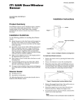
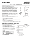
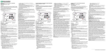
ITI Part Number 60-873-95 Sentrol/Caddx Part Number NX-488 ShatterPro® Glass Break Sensor Document Number 466-1841 Rev B April 2001 Installation Instructions Product Summary Installation Guidelines The ShatterPro® omnidirectional glassbreak sensor provides 360 degree coverage. It can be mounted on the ceiling, or on the opposite wall, or on adjoining walls. It has a range of up to 20 feet for glass panes 1 x 2 (0.3m x 0.6 m) or larger. ❑ For best detection, avoid installing in rooms with lined, insulating, or sound deadening drapes or rooms with closed wooden window shutters inside. ❑ Dont use near an air compressor. A blast of compressed air may cause a false alarm. ❑ Avoid stairwells, glass booths, and all rooms smaller that 10 x 10 (3 m x 3 m). ❑ The Pattern Recognition Technology of the ShatterPro ignores most false alarm sounds. Some sounds can duplicate the glass break pattern the ShatterPro detects, however, so the ShatterPro works best in rooms with only moderate noise. Avoid rooms where white noise, such as a fan, is present. Avoid rooms with noisy areas or multiple noise sources such as small kitchens or bathrooms, garages, etc. 4.24" 10.8 cm 1.70" 4.3 cm 3.13" 8.0 cm Note For glass break protection in these applications (where ShatterPro is not appropriate), use shock sensors on the windows or window frames. Figure 1. The ShatterPro Glass Break Sensor The maximum detection range is 20 (6 m) for plate, tempered, laminated and wired glass. For armor-coated glass, the maximum detection range is 12 (3.65 m). Coverage is measured from the sensor to the point on the glass farthest from the sensor (see D and D in Figure 2). See Specifications for recommended glass thickness. D ❑ Avoid adding (learning) the sensor into 24-hour sensor groups, where the sensor will be armed even when the room is in use. Like a motion detector, a glass break sensor may be tripped when occupants are in the protected area. Adding the ShatterPro to a perimeter sensor group, which is armed only when the perimeter doors and windows are armed, will help prevent false alarms. ❑ Do not install in humid rooms. The ShatterPro is not hermetically sealed. Excess moisture on the circuit board can eventually cause an electrical short and possibly a false alarm. ❑ The sensor can be mounted as close as 3.3 (1 m) from the glass. D D' Maximum distance (D) from the ShatterPro to the glass must not exceed 20' 20 ' D is distance from glass The optimum performance zone is distance D in either direction on the glass. Wireless ShatterPro Tools Needed Figure 2. Optimum performance zone Note ShatterPro may not consistently detect cracks in glass, or bullets that break through the glass. Glassbreak sensors should always be backed up by interior protection. ❑ Phillips screwdriver ❑ Sentrol 5709C hand-held tester Installation Use the following procedure to install the ShatterPro. 1. Choose a mounting location. Since the sound of breaking glass travels straight out from the broken window, the best location for mounting the sensor is the wall opposite the window--assuming the glass to be protected is within the sensor range and line of sight. The ceiling and adjoining (side) walls are also good sensor locations. A ceiling mounted sensor will have better detection if located 6-10 (2-3 m) back from the glass rather than directly above the glass. Important ! DO NOT EXCEED THE 20’ MAXIMUM DETECTION RANGE OF THE SHATTERPRO. While the sensor may function beyond the 20’ range, it could miss a minimum output glassbreak. Furthermore, changing conditions in the room, such as rearranging furniture, could reduce the range of the sensor back to 20’. 2. Remove the cover from the ShatterPro base. Hold the base against the wall or ceiling at the desired mounting location. Insert screws through the two mounting holes in the base to attach it to the mounting surface. CAUTION You must be free of all static electricity before handling the transmitter circuit board. Touch a grounded, bare metal surface before touching the circuit board, or wear a grounding strap. Cover 3V Batteries Base Figure 4. Battery installation Testing the ShatterPro Pattern Recognition Technology of the ShatterPro ignores most false alarm sounds, including glassbreak testers, so the ShatterPro must be set to test mode during Mounting holes Figure 3. Mounting holes (back view of the ShatterPro) 3. 4 2 Insert two 3V batteries as shown in Figure 4 and replace the cover. Use the procedures in the following sections, Testing the ShatterPro and Testing the System, to make sure the sensor is working properly with the panel. Figure 5. Testing the ShatterPro the following procedure (see step 2). When the sensor is in test mode, processing of the glassbreak pattern in the upper and lower frequencies is disabled. The ShatterPro is then listening only for the mid-range frequencies, which the tester reproduces. It is these frequencies that determine the sensor detection range. The ShatterPro is designed to detect the breaking of framed glass mounted in an outside wall. Testing the sensor with unframed glass, such as broken bottles, etc., may not trip the sensor. Use the Sentrol 5709C hand-held tester and the following procedure to test the ShatterPro. 1. Set the tester to tempered glass. Note The 5709C tester has a different setting for each type of glass. You should always set the tester for tempered or laminated glass (either is correct and both have the same range) unless you are certain that all the glass to be protected is plate glass. 2. Hold the tester speaker directly on top of the sensor and activate the tester. The sensor will alarm, then it will go into test mode for one minute. While in the test mode, the LED on the sensor will blink continuously. Note Extend the test mode time by activating the tester at least once a minute. 3. Holding the tester near the surface of the glass and behind any closed drapes or blinds, aim the tester at the ShatterPro and hold down the test button (see Figure 5). Note Remember, the ShatterPro should not be installed in rooms with lined, insulating, or sound deadening drapes or rooms with closed wooden window shutters inside. 4. Observe the LED on the sensor. If the sensor is detecting the tester signal, the LED will remain on but will stop blinking momentarily. This indicates the sensor is mounted within range and is working properly. Adding the ShatterPro to Panel Memory The following procedure is a general guideline for adding (learning) the sensor into panel memory. Refer to your panel installation instructions or reference manual for complete details. 1. 2. 3. 4. 5. 6. Set the panel to Program mode. Proceed to the LEARN SENSORS menu. Select the appropriate sensor group and sensor number. Trip the tamper switch on the sensor. Repeat the above steps until all sensors are added (learned) into the panel. Exit Program mode. Testing the System The following steps describe general guidelines for testing the sensor. Refer to your panel installation instructions or reference manual for complete details. 1. 2. 3. Set the panel to the Dealer Sensor Test mode. Use the hand-held tester to trip the sensor. Listen for status beeps (or a voice message) to indicate that the panel is receiving transmissions from the sensor OR Look for a message on the touchpad display. Note Refer to you panel installation instructions for troubleshooting information. Note If the sensor LED blinks continuously when the test button is pressed, the sensor is not detecting the tester signal. Replace the tester battery if you suspect it is not producing a strong signal. If you are certain that the tester signal is strong, reposition the sensor closer to the window and retest. Add more sensors if necessary to achieve complete coverage. 5. The sensor will automatically exit test mode if it does not sense any signals for 1 minute. The “Hand Clap” Test You can test the ShatterPro without enabling the test mode by clapping your hands loudly under the sensor. This sound will not trip the alarm, but the sensor LED will blink twice. This is a signal that the sensor has power and that the microphone and circuit board are functioning. 3 Specifications Notices Compatibility All ITI 319.5 MHz Learn Mode panels; All Caddx 319.5 MHz panels Housing material: Flame retardant ABS Dimensions: 4.24 (10.8 cm) length 3.13 (8.0 cm) width 1.70 (4.3 cm) depth Operational voltage: 2.6 to 4.5 VDC Current draw: 26µA typical average Battery Life: 5 years typical If this equipment does cause harmful interference to radio or television reception, which can be determined by turning the equipment off and on, the user is encouraged to try to correct the interference by one or more of the following measures: ❑ Reorient or relocate the receiving antenna. Batteries: (2) Duracell DL 123A 3V Lithium ❑ Increase the distance between the equipment and receiver. Transmitter Frequency: 319.5 MHz ❑ Connect the equipment into an outlet on a circuit different from that to which the receiver is connected. Transmitter Conditions: Alarm, Tamper, Low Battery Supervisory ❑ Consult the dealer or an experienced radio/TV technician for help. RF Immunity: 20V/meter 1MHz to 1000 MHz Microphone: Omnidirectional electret Operating Temperature Range: 32° to 120°F (0° to 50°C) This equipment has been tested and found to comply with the limits for a Class B digital device, pursuant to Part 15 of the FCC Rules. These limits are designed to provide reasonable protection against harmful interference in a residential installation. This equipment generates, uses and can radiate radio frequency energy and, if not installed and used in accordance with the instructions, may cause harmful interference to radio communications. However, there is no guarantee that interference will not occur in a particular installation. This device complies with Part 15 of the FCC Rules. Operation is subject to the following two conditions: (1) This device may not cause harmful interference, and (2) this device must accept any interference received, including interference that may cause undesired operation. FCC ID: B4Z-799A-SOUND Storage Temperature Range: -30° to 140°F (-34° to 60°C) Max. Humidity: 90% Relative Humidity (noncondensing) Recommended Glass Size: Minimum 1' x 2' (0.3m x 0.6m) or larger Glass thickness: Plate: 3/32" to 1/4" (2.4mm to 6.4mm) Tempered: 1/8" to 1/4" (3.2mm to 6.4mm) Wired: 1/4" (6.4mm) Laminated: 1/8" to 1/4" (3.2mm to 6.4mm) 2266 Second Street North | North Saint Paul Mn | 55109 | 800-777-2624 | www.interlogixinc.com © 2001 Interlogix, Inc. Interlogix, Learn Mode, and Pattern Recognition Technology are trademarks of Interlogix, Inc. ITI, Sentrol, and ShatterPro are registered trademarks of Interlogix, Inc. Protected under US patents including: 3,863,250; 4,745,398; 4,837,558; 4,885,713; 5,192,931; 5,805,063; 5,776,206; 5,872,512; 5,942,981; and other patents pending. 4