1
List of Tables
Intel® Server Board S2600CW Family TPS
List of Tables
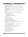
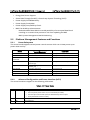
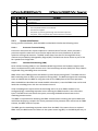
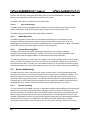
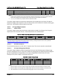
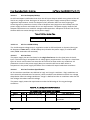
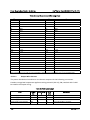
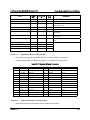
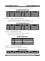
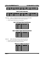
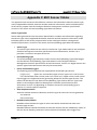
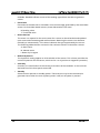
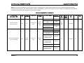
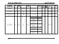
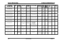
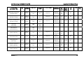
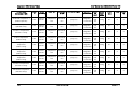
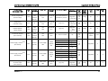
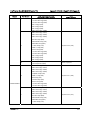
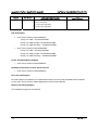
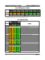
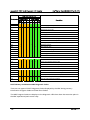
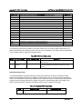
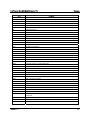
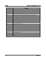
Table 1. Intel® Server Board S2600CW Feature Set......................................................................................... 3 Table 2. Mixed Processor Configurations ......................................................................................................... 18 Table 3. RDIMM Support .......................................................................................................................................... 25 Table 4. LRDIMM Support........................................................................................................................................ 25 Table 5. Intel® Server Board S2600CW DIMM Nomenclature................................................................... 26 Table 6. Video Modes ................................................................................................................................................ 45 Table 7. External RJ45 NIC Port LED Definition ............................................................................................. 52 Table 8. Setup Utility – Security Configuration Screen Fields .................................................................. 54 Table 9. ACPI Power States ..................................................................................................................................... 62 Table 10. Processor Sensors .................................................................................................................................. 70 Table 11. Processor Status Sensor Implementation.................................................................................... 71 Table 12. Fan Profile Mapping ............................................................................................................................... 82 Table 13. Component Fault LEDs......................................................................................................................... 85 Table 14. Basic and Advanced Server Management Features Overview ............................................. 89 Table 15. Main Power Connector Pin-out......................................................................................................... 98 Table 16. CPU_1 Power Connector Pin-out ..................................................................................................... 98 Table 17. CPU_2 Power Connector Pin-out ..................................................................................................... 98 Table 18. Front Panel Header Pin-out................................................................................................................ 99 Table 19. Front Panel USB 3.0 Connector Pin-out .................................................................................... 100 Table 20. SATA 6Gbps Connector Pin-out .................................................................................................... 100 Table 21. Mini-SAS HD Connectors for SATA 6Gbps Pin-out ............................................................... 100 Table 22. Mini-SAS HD Connectors for SAS 12Gbps Pin-out ............................................................... 101 Table 23. HSBP I2C Header Pin-out .................................................................................................................. 101 Table 24. HDD LED Header Pin-out.................................................................................................................. 102 Table 25. Type-A USB Connector Pin-out ..................................................................................................... 102 Table 26. eUSB SSD Header Pin-out ............................................................................................................... 102 Table 27. M.2/NGFF Header Pin-out ................................................................................................................ 102 Table 28. RMM4 Lite Connector Pin-out ........................................................................................................ 104 Table 29. TPM Connector Pin-out .................................................................................................................... 104 Table 30. PMBus* Connector Pin-out .............................................................................................................. 104 Table 31. Chassis Intrusion Header Pin-out ................................................................................................. 104 Table 32. IPMB Connector Pin-out ................................................................................................................... 105 Table 33. 6-pin System FAN Connector Pin-out ........................................................................................ 105 Table 34. 4-pin System FAN Connector Pin-out ........................................................................................ 105 Table 35. CPU FAN Connector Pin-out ........................................................................................................... 106 x
Revision1.11