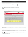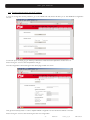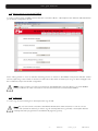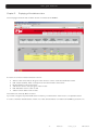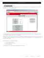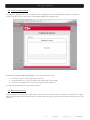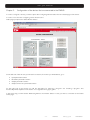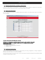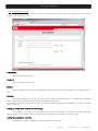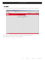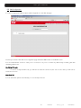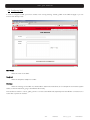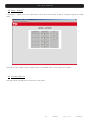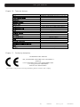
1
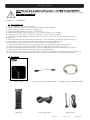
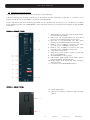
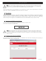
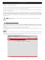
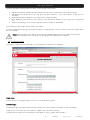
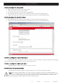
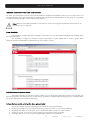
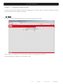
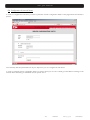
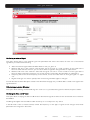
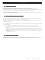
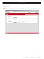
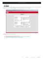
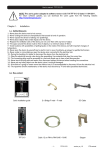
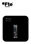
RCM 310
USER’S MANUAL
User’s guide · RCM 310
NOTE: This user’s guide is adapted to software version v.1.0.2 of RCM 310 dated 13/07/2011.
For future software updates, you can download the user’s guide from the following website:
http://www.ftemaximal.com/
Chapter 1.
Installation.
1.1. Safety Measures
1.- Never place the device next to hot sources.
2.- Never undergo the device to temperatures that exceed its level of operation.
3.- Never expose the device to leakings nor spatterings.
4.- Never place objects that contain liquids over the device.
5.- Respect the ventilation slots of the device, do not cover them with any kind of object.
6.- The space around the device must be free of objects, in a minimum radius of 40cm.
7.- Avoid locations with possibilities of spilling liquids on the inside of the device, and with important changes of
temperature.
8.- Never open the device by yourself due to electric risk. In case of problems, go always to qualified technicians
9.- Never, under no circumstances, open the device when connected to the electrical net.
10.- During the handling it is better to disconnect the device from the electrical net.
11.- Obey the electricity security rules during the assembling. Use materials that obey the current law.
12.- The connecting plug must be accessible in a fast and simple way to have a fast disconnection.
13.- Never touch the plug with wet hands. Also, disconnect always the device before handling the connections.
14.- Never put any heavy object over the device, since it could get damaged.
15.- If the device is going to remain some time without use, it is recommendable to disconnect it from the electrical net.
16.- The repairmen and the maintenance of the device must be done by TV and radio specialised technicians.
1.2. Box content
User’s manual
Cable 12 cm PIN to PIN RJ45 – RJ45
Cable 50 cm PIN to PIN RJ45 – RJ45
RCM 310
Power supply cable
GSM Antenna
-1-
RCM 310
version_en_1.0
FTE maximal
User’s guide · RCM 310
1.3. Description and connections
The RCM310 is the remote control unit for the devices of the 310 family.
It allows monitoring and remotely controlling up to 72 devices from the 310 series (at the rate of a maximum of 18
devices for each one of the four DVBUS connectors of the RCM 310).
It has a web server that allows controlling the RCM from any browser (we recommend you to use Firefox for a better
usage experience). It also has a GMS/GPRS modem that allows sending and receiving text messages, as well as GPRD
connections.
RCM310 – FRONT PANEL
1.
BOOT button: It allows rebooting the RCM 310 to
the initial status by default.
2. Green Led L2*: Programmable Led that allows
pointing out the different status of the device.
3. Red Led L1*: Programmable Led that allows
pointing out the different status of the device.
4. RJ45 1 and 3 DVBUS connectors that allow
connecting up to 18 DVBUS devices each.
5. RJ45 2 and 4 DVBUS connectors that allow
connecting up to 18 DVBUS devices each.
6. USB Host connector 2.0.
7. Ethernet connector for the connection to the web
server of the RCM310.
8. RF 47-862MHz monitoring input
9. Optocoupled digital inputs S1-S4 (inputs without
voltage) that allow activating alarms.
10. Relay outputs OUT1-OUT4 that allow controlling
external devices.
11. Connection for the GSM/GPRS antenna.
RCM310 – REAR PANEL
12. Power supply input.
13. SIM card connector to enable the SMS and GPS
options.
12
13
-2-
RCM 310
version_en_1.0
FTE maximal
User’s guide · RCM 310
The main functions that can be remotely done with RCM310 are:
•
•
•
•
•
•
•
•
•
•
•
•
•
Displaying the general and/or detailed status of all the connected devices.
Modifying the parameters of each one of the connected devices.
Creating and using programs which are compatible to field strength meters from Mediamax EVO and MINI series
in order to configure the devices with the information inside the files of the mentioned programs.
Updating the firmware of one or all the compatible devices that are connected to the RCM 310.
Creating and implementing back-up copies with the global configuration of the system, which simplifies the
cloning process of identical installations.
Checking, downloading and deleting the global events file of the system, which brings together all the stored
messages in the system.
Monitoring the status of all the devices and activating alarms when the monitored parameters are out of the set
limits.
Monitoring the output power or level of the connected devices and activating alarms when those levels are out of
the configured ranges.
Monitoring power or level of the signals that are connected to the system and activating alarms when those levels
are out of the configured ranges
Activating and / or deactivating alarms depending on the status of the digital inputs (S1-S4).
Activating and / or deactivating each one of the relays when getting in or out an alarm, which allows for example
activating a siren or external fan, or cutting the power of several power supplies that are connected to the
installation.
Sending e-mails and / or text messages during the activation and deactivation of the alarms.
Generating alarms when receiving text messages.
1.4. Connecting the DVBUS to the system
The devices are connected to the DVBUS through the BUS1 – BUS4 connectors. Keep in mind that you can connect up
to 18 devices for each BUS connector, which makes a total of 72 devices if we bring the 4 connectors together.
The devices will appear divided into groups for each Bus connector in the homepage.
1.5. Connecting the optocoupled digital inputs and the relay outputs
The four digital inputs S1 – S4 are contact inputs. In order to activate them you should make a short circuit between the
chosen output and the adjacent common contact “COM”. A short circuit is equivalent to an active output.
Note: Do not run any voltage (DC or AC) on the digital inputs since you would take the risk of destroying them.
The four inverter relays OUT1 – OUT4 allow activating or deactivating any kind of signal, as long as you do not go beyond
the 250VAC in their contacts nor the 3AMP power. The contacts NO / NC are available so you can have a short circuited
or opened output when it is active as well as when it is inactive.
1.6. Connecting the RF monitoring input
The RF monitoring input allows monitoring signals in the frequency range of 47-862Mhz, and width range of 65 from 105
dBuV.
1.7. Installing the SIM card – GSM Antenna
The SIM panel should be inserted in the corresponding cavity in the back panel. Use the snap fastener in order to avoid
that the card could move from its place.
-3-
RCM 310
version_en_1.0
FTE maximal
User’s guide · RCM 310
Note: If you insert the SIM card while the device is on, the modem will not detect it. You will have to turn the
device off and on so it can be detected by the modem. If you do not insert any SIM card in the RCM310 the
features concerning neither the SMS nor the GPRS browsing will not be available.
The provided GSM antenna should be plugged in the corresponding connector in the front panel. Keep in mind that the
system will not detect any GSM/GPRS net unless the antenna is connected.
1.8. Boot sequence
The RCM 310 switches on the Led 1 during the boot sequence. This Led remains switched on during the boot sequence
(it lasts one minute and a half approximately). It is not possible to establish connections with the web service of RCM 310
until the boot sequence is finished. Once the sequence is finished, the led L1 switches off (or turns into its corresponding
status according to the configuration of the RCM 310), which means that the RCM is ready to operate normally.
1.9. Connecting to the RCM310 through Ethernet
In order to connect to the RCM 310 through Ethernet, it must be connected to a net.
The IP address by default of the RCM 310 is:
192.168.1.227
Note: Make sure that there are no other devices with this same IP address in the net. If any doubts connect
directly (with a straight or crossed RJ45 cable) to the RCM 310 in order to avoid problems in the net. Once
connected to the RCM 310 you will be able to change the configuration in order to adapt it to the net where it
will be connected.
1.10. Connecting to the web server of RCM310
Log in the browser and write down the IP address of the RCM 310 in the address bar. If everything has run properly, you
will see the connection window of the web server.
-4-
RCM 310
version_en_1.0
FTE maximal
User’s guide · RCM 310
The password by default of the RCM 310 is:
00000
Note: It is important to change it to a different password. The password by default is a temporal password that
does not offer security enough for a device that has to be connected to a net.
Enter the password and you will gain access to the main page of the RCM 310.
In the main page you will be able to see a general status of the system, with the connected devices and a summary of the
status of the devices.
In the top browsing bar you will see the alias of the system (the name that identifies the system, configurable in the “RCM
310” tab) as well as the software version that is installed in the RCM 310.
In the lower status bar on the left, you will see the flag icon that you can use in order to change the language of the
interface, as well as the status of the GSM modem (on the right)
Note: The first time you connect to the RCM 310, you will not see any device connected to the system in the
main page. In order to detect the devices that are connected into the system you will have to make a search of
devices in the “Devices” window.
-5-
RCM 310
version_en_1.0
FTE maximal
User’s guide · RCM 310
1.11. Changing the password and the IP address
In order to change the access password go to the “RCM 310” tab, which will lead you to the RCM310 configuration
window.
Scroll down up to “modifying log in” where you will have to write the current password and the new one.
Press “Change” in order to save the password change.
The net configuration can be changed in the same page, a little more down.
Change the necessary fields in order to adapt the RCM configuration to the net where it will be connected.
Press “Change” in order to save the changes in the net configuration.
-6-
RCM 310
version_en_1.0
FTE maximal
User’s guide · RCM 310
1.12. Making searchs of connected DVBUS
In order to make a search of DVBUS devices that are connected to BUS1 – BUS4 press in the “Devices” tab that will lead
you to devices configuration window.
Press “making search” in order to start the searching process of devices in the DVBUS. This process will take several
seconds, depending on the number of devices connected. Once the search is finished you can go to the homepage to see
the modules list and proceed to their configuration.
Note: In case you wish to connect more devices into the RCM310 by connecting them to one of the DVBUS
ports, you will have to make a new search once the new devices are connected to the DVBUS.
1.13. Logging off
In order to log off (disconnecting from server) press the “log off” tab.
Note: Only one user can be connected to the RCM 310 web server at the same time. In order to connect
another user (another IP address) you have to log off manually (with the “log off” tab) or let it expire after the
inactivity time that is programmed in the “RCM 310” page has gone by.
-7-
RCM 310
version_en_1.0
FTE maximal
User’s guide · RCM 310
Chapter 2.
Displaying of the devices status
The homepage shows the lists of all the devices connected to the DVBUS.
For each one of the connected devices it is shown:
•
•
•
•
•
•
Alias: It is the name that can be given to the device in order to make its identification easier
UID: Unique identifier, which corresponds to the serial number of the device
Model: Specific model of the device
SW version: Version of the program of the module
HW: Hardware version of the module
Status: Current status of the module
The devices are sorted by BUS connector.
If you have configured any external RF to be monitored, you will see them in the list too, in a separate section.
In order to check the detailed status of each one of the devices that are connected to the DVBUS, just click on it.
-8-
RCM 310
version_en_1.0
FTE maximal
User’s guide · RCM 310
2.1. Device Status Page
The device status page will let you see the detailed status of the selected device. From the status page of each device you
will be able to go to its configuration page.
The page shows the current status of the selected device, with the same information that is given in a field strength meter
from the Mediamax MINI or EVO family, or in the PRO201.
With the arrows in the low part of the window, you will be able to navigate through all the devices that are connected to
the DVBUS, regardless of the DVBUS connector they are connected to. You will be able to move to the next, previous, first
and last device of the list.
From this window you can get to three options:
•
•
•
Common Interface window.
Device configuration window.
Device rebbot button.
The configuration of the devices will be explained in the next chapter.
-9-
RCM 310
version_en_1.0
FTE maximal
User’s guide · RCM 310
2.2. Common Interface Menu
The option for getting to the Common Interface menu only appears in those devices that have that kind of interface.
This window allows going to the menus of the installed CAM in the selected device.
If there are connected CAMs, they will appear on the menu with their names.
•
•
•
Press one of them in order to go to the card menu.
Press the start icon in order to go back to the starting menu of the CAM
Press the move back arrow in order to go a level up in the CAM menu.
In order to leave the CAM menu, just close the window.
2.3. Rebooting the device
Press this button in order to reboot the chosen device. The device will be rebooted (it will turn off and then on again).
Keep in mind that the device will take around a minute to be ready again from the moment when the rebooting order has
been sent.
- 10 -
RCM 310
version_en_1.0
FTE maximal
User’s guide · RCM 310
Chapter 3.
Configuration of the devices that are connected to the DVBUS
In order to configure a device, you have to press the “Configuring Device” button from the Status page of the device.
In order to move from the configuring device window to the
Status page just press the “Status Device” button.
On the left side of the window you will see four sections, from them you will be able to go to:
•
•
•
•
Input parameters edition
Modulator parameters edition
Output parameters edition
Output services and parameters edition
On the right side of the window you will see the button for “Running a Program” and “Creating a program”. This
functionality will be explained in the section of configuration through programs.
In the same way, you will have the “Rebooting Device” and “Device Status” in case you wish to come back to the Status
device page.
- 11 -
RCM 310
version_en_1.0
FTE maximal
User’s guide · RCM 310
3.1. Editing the input parameters – modulator – output channel
In each one of these sections, you will be able to modify the input parameters, modulator and output cannel of the device.
Check the user’s guide of the chosen device in order to get the details of each option.
3.2. Changing the output services
You can modify them by pressing the “configuring output services” button in the output services section. The following
window will appear:
For each service shown in the list you will be able to:
Validate it, by selecting it in the “validate” column (it makes the service available in the output).
Decrypt it, by selecting it in the “decrypt” column (only for the Common Interface devices).
Editing SID (Service Id).
• Editing the HD SIMULCAST.
• Editing the LCN (Logical channel numbering).
• Editing the name.
3.3. Configuring through programs
Programs can be created in order to configure the devices quickly, and re-using configurations, or making configurations
back-ups of the devices that are connected to the DVBUS.
The format of the programs is the same as the one used in the programs created with strength field meter Medimax MINI
and EVO for programming the modules.
- 12 -
RCM 310
version_en_1.0
FTE maximal
User’s guide · RCM 310
In order to create a program with the content of the configuration of the selected device, just press “Creating a program”.
This will generate a .prg file with the content of the configuration of the selected module and it can be saved in your
computer.
In order to implement a program in the device, just press the “Implementing a Program” button. Then you will be able to
select the .prg file that you want to run in the device from your own computer.
Note: You also will be able to create and implement programs globally to all the devices that are connected to
the DVBUS from the “Devices” page.
- 13 -
RCM 310
version_en_1.0
FTE maximal
User’s guide · RCM 310
Chapter 4.
Alarms and actions
One of the main features of RCM 3140 is the capacity of continually monitoring the status and output level of the devices
that are connected to the DVBUS, as well as the level of the external RF signals.
The system allows setting alarm status, which once activated will generate several actions, and once deactivated will
generate other different actions.
An alarm can be created by configuring a series of events that must take place in order to get the alarm activated. When
the configured requirements take place, the alarm gets activated. The actions that have to happen so the alarm gets
activated are defined in the alarm configuration. Once the necessary events in order to get the alarm activated disappear,
the alarm is deactivated. The actions that should take place when the alarm gets deactivated are defined in the alarm
configuration too.
Note: The alarm status does not get stored, therefore when the system is rebooted, if there was any active
alarm it will be removed.
4.1. Definition of system monitoring cycle
The RCM 310 is checking the status of the devices that are connected to the DVBUS all the time. This monitoring is
made in a sequential way. The more modules are connected to the DVBUS, the more time the cycle will take. The cycle
can last around one second for less than 6 connected devices, and several seconds when the total of 72 devices are
connected.
In the monitoring cycle are included the external RF signals and SMS reception too.
The digital inputs are asynchronously monitored (they are treated immediately instead of waiting until the end of the
monitoring cycle).
Alarm list
In order to move to the alarm list you have to go to the “Alarm” page situated in the upper tabs of any page of the
RCM310.
In the system you can define as many alarms as you wish. The alarms are treated depending on priorities; the most urgent
one is placed at the top of the list and the less one at the bottom.
- 14 -
RCM 310
version_en_1.0
FTE maximal
User’s guide · RCM 310
The alarm list allows checking all the set alarms, as well as their current status:
•
•
•
•
•
Validate: If the field is activated, the alarm will be processed. If it is not activated, it will not be processed.
Edit: By pressing the pencil icon you will get to the alarm definition so you will be able to modify it if it is
necessary.
Delete: By pressing the delete icon you will proceed to delete the alarm.
Move: By pressing the arrows you can scroll up or down the alarm in the list in order to give more or less priority
to it.
Status: If the warning is on, the alarm is activated. On the contrary it is deactivated.
The “Creating an alarm” button allows creating a new alarm.
In order to implement the changes, the “Implement” button must be pressed. In case you want to cancel the changes press
the “Cancel” button.
Note: When the status of any alarm in the list changes (Validate, Delete or Move) the alarm process will be
stopped. The alarm process comes back once the changes are implemented or cancelled.
4.2. Configuring alarms
The creation / edition window of the alarms is very extensive and requires a lot of attention.
Alarm name
The first thing to do is giving the alarm a name, so it can be easily recognized.
Activation type
The activation type of the alarm defines how the conditions in order to activate / deactivate an alarm are treated:
Simple: If one of the events set on the definition happens, the alarm will be activated.
Combined: All the events set on the definition must happen in order to get the alarm activated.
- 15 -
RCM 310
version_en_1.0
FTE maximal
User’s guide · RCM 310
Activate according to the devices status:
•
•
•
•
•
Warning. The device moves to the warning status.
Error. The device moves to the error status.
No answer. The device does not answer to the RCM310.
RF range OK. The level measured in the output of the device is within the specified range.
Signal out of range. The level measured in the output of the device is out the specified range.
Activate according to the external RF Status:
•
•
RF range OK. The level measured in the output of the device is within the specified range.
Signal out of range. The level measured in the output of the device is out the specified range.
Activation according to the status of other alarms
The system is able to use another alarm as a source of alarm. This allows creating complexes alarms settings,
where previous alarms must take place in order to generate other ones.
Activation according to the digital inputs status
A digital input that is opened or closed is a source for an alarm.
Activation when receiving a text message
The SMS reception with a predefined message can be used as a source for generating an alarm.
Note: When using the SMS reception as an alarm source it is important to use the “Immediate deactivation of
the alarm once activated” option, since in order to deactivate the alarm the requirements for starting it must stop
and there is no contrary when receiving the SMS. Therefore, if the immediate deactivation is not chosen, the
alarm generated by the SMS reception will remain active every time.
- 16 -
RCM 310
version_en_1.0
FTE maximal
User’s guide · RCM 310
Immediate deactivation of the alarm once activated
An alarm gets deactivated once the causes that activated it disappear. Nevertheless, there are some cases where it is
interesting that the alarm gets deactivated immediately, although the events that activated it are still going on (for example
in cases of activation by SMS or when rebooting the system).
Note: When the immediate deactivation of the alarm is chosen, the configured deactivation actions will run (in
case there is any configured).
Alarm Sensitivity
It is possible to configure the alarm sensitivity, so the alarm does not get activated/deactivated immediately when
the events take place.
The sensitivity is configured in number of cycles. The number of cycles implies that, in order to get the alarm
active, the events must take place continually during a set number of cycles
Activation when the system reboots
The system rebooting can be set as cause of alarm. You can select if the rebooting has been forced by the user
(the rebooting button has been pressed) or if the rebooting has been unexpected (the feeding has gone or there has been
any system failure that has caused the rebooting).
Actions that are carried out when the alarm gets activated
•
•
•
•
This section defines the actions that will be made when the alarm gets activated.
Modifying leds status: You can make that each one of the Leds turns on, off or remains flicking.
Modifying relay status: You can open, close or reverse the status of each one of the 4 relays.
Sending an e-mail: You can send a pre-configured e-mail (defined in the “mail” tab).
Sending a SMS: You can send a pre-configured SMS (defined in the “GSM” tab).
- 17 -
RCM 310
version_en_1.0
FTE maximal
User’s guide · RCM 310
Actions that are carried out when the alarm gets deactivated
This section defines the action that will be made when the alarm gets deactivated. The possible actions are the same as
the ones made when the alarm gets activated, but are independently configured, so different actions can be carried out
when activating and deactivating the alarm.
- 18 -
RCM 310
version_en_1.0
FTE maximal
User’s guide · RCM 310
Chapter 5.
Configuration of Mail and GSM
In order to send e-mails and SMS you must have configured them in advance. There is a general configuration and each
e-mail and SMS has to be configured individually.
5.1. Mail list
The page with the mail list is quite simple, and we can get to it through the “mail” tab.
There is a button for creating a new e-mail, as well as a button for configuring the mail server.
The list allows editing or deleting any of the created e-mails
- 19 -
RCM 310
version_en_1.0
FTE maximal
User’s guide · RCM 310
5.2. Configuration of the mail Server
In order to configure the mail server you have to press the “Server Configuration” button in the page where the mail list is
placed.
The necessary standard parameters are at your disposal so you can configure the mail server.
In order to check the server configuration there is a section where you can send a testing e-mail. Write an existing e-mail
address where the testing e-mail will be sent, and press “send”.
- 20 -
RCM 310
version_en_1.0
FTE maximal
User’s guide · RCM 310
5.3. Configuring an e-mail
In order to configure an e-mail, you have to create one by pressing “Create e-mail” in the page where the mail list is
placed, or edit an existing e-mail.
E-mail Name
Enter the name of the e-mail.
Recipient
Enter the recipient of the e-mail.
Subject
Enter the subject of the e-mail. You will be able to attach automatic fields to the subject, as for example date and
time.
Message
Enter the message of the e-mail. You will be able to attach automatic fields, as for example the summarized
status of the system, or the link that allows going to the RCM310 remotely.
This last field is useful in order to obtain a link to connect to RCM310, specially when the RCM is connected to a router
with a dynamic IP.
Adding an Events file in the body of the message
It is possible to add a part of the events file in the body of the message. It can be set in number of lines (the
specific number of lines will be included, being those the most recent ones) as well as in number of days.
Adding the compressed event file
It is possible to add the complete compressed events file in .zip format.
- 21 -
RCM 310
version_en_1.0
FTE maximal
User’s guide · RCM 310
5.4. SMS List
You can go to the page where the SMS list is by pressing the “GSM” tab. It is very similar to the e-mail list page.
There is a button for creating a new message, as well as a button for configuring the SIM card.
The list allows editing or deleting any of the created messages.
- 22 -
RCM 310
version_en_1.0
FTE maximal
User’s guide · RCM 310
5.5. SIM Configuration
In order to configure the SIM card press “SIM Configuration” in the SMS list page.
The first you will see in the SIM card configuration page will be the IMEI number of the GSM modem.
You can deactivate the modem in case you do not need it or if you do not have any SIM card by unmarking the field
“Activating GSM mode”.
Modifying PIN code
In order to modify the PIN code, you will have to enter the current one, the new one and then you will have to
confirm the new one.
Operators list
You can select the operator automatically, or do it manually in the list.
- 23 -
RCM 310
version_en_1.0
FTE maximal
User’s guide · RCM 310
5.6. Configuring SMS
In order to configure a SMS, you have to create a new one by pressing “Creating SMS” in the SMS list page or you can
edit one that already exists.
SMS Name
Enter the name of the SMS.
Recipient
Enter the recipient’s telephone number.
Message
Enter the message of the SMS. You will be able to attach automatic fields, as for example the summarized system
status, or the link that allows going to the RCM 310 remotely.
This last field is useful in order to getting a link to connect to the RCM 310, especially when the RCM is connected tom a
router with a dynamic IP address.
- 24 -
RCM 310
version_en_1.0
FTE maximal
User’s guide · RCM 310
Chapter 6.
RCM310 Configuration
The RCM 310 tab leads to the typical configuration options of the RCM 310
6.1. Updating the system
This button allows updating the RCM 310 firmware. A window will be opened by pressing “Updating”. It will allow choosing
an updating file for the RCM 310 (ftgepkg kind of file).
The file will be transferred from the hard disk of the PC where you are navigating to the RCM 310.
6.2. Rebooting the system
This option allows rebooting the RCM 310. There are two options of rebooting:
• SW Reset: The RCM 310 program gets rebooted, but it is just a software matter, none of the system supplies
turns off.
• HW Reset: The HW gets rebooted and the main supply gets cut. This kind of reset guarantees that all the inner
components of the RCM 310 are rebooted.
6.3. Saving – Restoring the system configuration
The “Saving system configuration” option generates a file that contains the current configuration of the RCM. This file
contains:
•
•
•
•
•
RCM310 alias.
Detected modules.
Alarms.
E-mails and SMS.
Everything inside of the “RCM310” tab.
- 25 -
RCM 310
version_en_1.0
FTE maximal
User’s guide · RCM 310
The “Restoring system configuration option” modifies the current configuration of the RCM 310 with the values that are
included in the file.
Note: Saving and restoring the system configuration does NOT affect the devices that are connected to the
DVBUS. In order to modify the configuration of the devices that are connected to the DVBUS you have to use
the programs.
6.4. Modifying the System Alias
This option allows changing the name that the RCM 310 will have, and that will be visible in the status bar as well as in the
sent messages.
6.5. Modifiying the Log On
This option allows changing the current password for logging on for a new one.
Note: It is important to change it to a different password. The password by default (0000) is a temporal
password that does not offer security enough for a device that has to be connected to a net.
.
6.6. Modifying date and time
This option allows changing the date and time of the RCM 310.
Additionally you can configure the time zone.
- 26 -
RCM 310
version_en_1.0
FTE maximal
User’s guide · RCM 310
The available “Automatic Configuration” button allows loading the current values of the PC from where you are navigating.
The “Synchronizing all the devices” option allows sending the updated date and time to all the devices that are connected
by DVBUS to the RCM 310, so all the connected devices will have the same time as the RCM 310 (important option for
the coherence of the events file of the RCM 310).
6.7. Logging off after inactivity
This option sets how much time it will take to log off when there is no activity (that is, there are no operations made with
the RCM 310 from the browser). Keep in mind that only a user can be connected to the RCM 310 at the same time. In
case that you do not log off by using the corresponding tab, this option allows that after the chosen time has gone by, the
RCM 310 logs off automatically, allowing that other users can gain access to the RCM 310.
6.8. Net configuration
This option allows configuring the typical parameters of the net where the RCM 310 will be connected to. If you have any
doubts about the values you have to enter, seek advice from your network administrator, since the values that have to be
configured depend on the net where the RCM 310 is connected.
- 27 -
RCM 310
version_en_1.0
FTE maximal
User’s guide · RCM 310
Chapter 7.
Devices
The “Devices” page allows making several actions concerning the devices that are connected to the DVBUS, as well as
configuring the system RF levels. You can go to this page through the “Devices” tab.
7.1. Search of devices in the Bus
Press the “Making a search” button in order to start the process of searching devices in the DVBUS. This process will take
several seconds, depending on the number of devices that are connected.
Once the search is finished you can go to the “Homepage” in order to check the modules list, as well as proceed to their
configuration.
Note: If you wish to connect more devices to the RCM 310, by connecting them to one of the DVBUS ports, you
will have to make a new search once the new devices are connected to the DVBUS. When making a devices
search, the list of the previous devices is deleted, and only the found devices will be shown.
7.2. RF Signals and Alias
By pressing this button you will go to the window for the RF external signals administration, as well as for RF levels and
frequency configuration.
- 28 -
RCM 310
version_en_1.0
FTE maximal
User’s guide · RCM 310
Monitoring an external signal
This option allows adding a new external signal. The parameters that have to be entered for each one of the external
signal that you create are the following:
•
•
•
•
•
Alias: The external signal will be identified with the name you give to it.
Minimum RF: This is the minimum value that the signal can have in normal conditions. If the signal level is
becomes lower than this minimum, you can set an alarm configuration that generates an output action.
Maximum RF: This is the maximum value that the signal can have in normal conditions. If the signal level is
becomes higher up than this maximum, you can set an alarm configuration that generates an output action.
Frequency: This is the central frequency of the channel, it does not matter if it is an analogue signal or a digital
one.
Digital / Analogue: You have to specify if the monitored signal will be digital or analogue.
Once all the data has been filled press “create”. This will refresh the page and you will be able to create a new signal in the
signal list below.
Withdrawing an external RF signal
This option allows deleting an external RF signal. In order to do so, just select the signal from the list and press “delete”.
Modifying the Alias and RF limits
This option allows modifying the alias and RF limits for the external signals as well as for the devices that are connected to
the DVBUS.
The RF signals appear in the list without “UID” since they do not correspond to any device.
In the RF limits of the connected devices, neither the frequency nor the type of signal can be changed since these
parameters are configured in the device.
- 29 -
RCM 310
version_en_1.0
FTE maximal
User’s guide · RCM 310
7.3. Updating the Device Firmware
This option allows updating the firmware of the devices that are connected to the DVBUS.
By pressing “Updating” a window will appear. It will allow you to select a binary file for the firmware update.
The file will be transferred from the hard disk of the computer from where you are navigating to the RCM 310, where it will
be analyzed in order to search for the connected devices that are compatible to the transferred file.
A list with the different connected devices that are compatible to the transferred file will appear. You will be able to select
the devices where the firmware will be updated.
7.4. Creating / Implementing programs to all the devices
The “Creating a program with all the devices” option generates a program file with all the devices that are connected to
the DVBUS. This file will be stored in the computer from where you are navigating.
The “implementing a new program to all the devices” option will implement a program file to all the devices that are
connected to the DVBUS.
In cases where the configuration of the program file does not coincide exactly with the connected devices, the following
method will be applied:
•
•
•
•
If a device is found in the program but it is not physically connected to the system, it will be just ignored.
If a device that is physically connected to the system is not defined in the program, obviously it will not be
configured.
If the program has a lower number of devices than the devices physically connected to the system, the program
content will be applied according to UID increasing order of each device. The remaining devices will not be
configured.
If the program has more devices than those that are physically connected, they will be applied according to the
order defined in the program.
7.5. Rebooting all the devices in the BUS
This button allows launching a rebooting process in all the devices that are physically connected to the DVBUS. The time
that the devices need in order to be operative again after the reboot can change, depending on the model.
- 30 -
RCM 310
version_en_1.0
FTE maximal
User’s guide · RCM 310
Chapter 8.
Tools
The “Tools” page allows getting to different usefulness of the system, and we can reach it through the tab with the same
name.
- 31 -
RCM 310
version_en_1.0
FTE maximal
User’s guide · RCM 310
8.1. Events file
The events file stores all the important messages that have taken place in the RCM 310 as well as in any of the devices
that are connected to the RCM 310 DVBUS. The events file is stored in the inner SD card.
There are three options for the events file:
•
•
•
Refreshing: It updates the display of the file.
Downloading: It allows downloading the complete events file in your computer.
Deleting: It allows deleting the content of the events file
- 32 -
RCM 310
version_en_1.0
FTE maximal
User’s guide · RCM 310
8.2. Inputs – Outputs
In the inputs – outputs window you will be able to check their current status, as well as manually modifying the output
status.
The relays and leds outputs can be modified, but the only available option is inverting the current status.
8.3. Formatting SD card
This option allows formatting the inner SD card of the system.
- 33 -
RCM 310
version_en_1.0
FTE maximal
User’s guide · RCM 310
Chapter 9.
Restoring the system up to the inicial settings
It is possible to restore the RCM 310 up to its original default settings through a special procedure. This procedure is only
recommended in case the system does not answer, or might the parameters to gain access to the device are lost.
Note: The rebooting process of the RCM 310 to its default values is irreversible and it destroys all the data and
configurations that were stored in the device. It is recommended to have back-ups of the RCM 310
configurations.
The procedure for restoring the RCM 310 up to its default values is the following:
•
•
•
•
•
•
Turn the device off.
Press the “boot” button in the front panel with a sharpening object while connecting the supply to the device.
When the red led starts flicking you can let the “boot” button go.
The green led will turn on while the red one will remain fixedly on.
The red led will turn off after a few seconds and the Green led will remain on.
Once the Green led is on and the red one off, disconnect the supply of the device and connect it again. The
device will be restored up to its default settings and you will be able to connect to it with these settings.
- 34 -
RCM 310
version_en_1.0
FTE maximal
User’s guide · RCM 310
Chapter 10. Technical features
Item
Code
Input frequency margin
Input level
Input impedance
Measure precision
Digital inputs
Relay inputs
Modem
DVBUS RJ45 Ports
USB
Maximum number of DVBUS devices
Program interface
Processor
Operating System
Inner Flash disc
RAM
Running temperature
Supply
Maximum consumption 220V (W)
Size
Weight
RCM310
2003560 / 2003560-R (Assembled in rack 19”)
47-862 MHz
65 to 105 dBuV
75 Ohms
±2dB
4 (contact inputs, 0 Vdc máx)
4 (3A , 250VAC Max)
GSM / GPRS tribanda 900/1800/1900 Mhz
4
2.0 High speed Host
18 modules per port. 72 altogether
Servidor Web
Freescale IMx25 ARM9 400Mhz
Linux 2.6
SD Card 1 Gbytes
64 Mbytes
0ºC-45ºC
230VAC ±10%
10 W
75x265x150 mm
1,5Kg
Chapter 11. Conformity declaration
CONFORMITY DECLARATION
“WE , FTE MAXIMAL, DECLARE THAT THE PRODUCT
RCM 310
IS IN CONFORMITY WITH FOLLOWING DIRECTIVES
Low Voltage Directive 2006/95/EC
EMC Directive 2004/108/EC”
If you wish a copy of the conformity declaration, please contact to the company
- 35 -
RCM 310
version_en_1.0
FTE maximal
ESPAÑA
Mogoda, 110
Pol. Industrial Can Salvatella
08210 Barberà del Vallès
(Barcelona) España
Tel. 00 34 93 729 27 00
Fax. 00 34 93 729 30 73
[email protected]
www.ftemaximal.com
FRANCE
16 ZAE Les Mouilles
74570 Groisy
Tel. 00 33 450 68 80 17
Fax. 00 33 450 68 84 68
[email protected]
www.ftemaximal.com
ITALIA
Via Edison, 29
42040 Calerno di
Sant’Ilario d’Enza (RE)
Tel. 00 39 05 22 90 97 01
Fax. 00 39 05 22 90 97 48
[email protected]
www.ftemaximal.com
DEUTSCHLAND
Auf der Höhe, 8
44536 Lünen
Deutschland
Tel. 00 49 (0) 23 18 78 5 - 01
Fax. 00 49 (0) 23 18 78 5 - 200
[email protected]
www.ftemaximal.de
PORTUGAL
Rua José Carlos Ary dos Santos
A-das-Lebres (Loures)
2670-791 Santo Antão do Tojal
Tel. 00 351 219 83 87 00
Fax. 00 351 219 83 87 09
[email protected]
www.ftemaximal.com
UNITED ARAB EMIRATES
P.O.Box 262442
Jebel Ali Free Zone
Warehouse FZS5AB03
Dubai
Tel. 00 971 4 886 5700
Fax. 00 971 4 886 5701
www.ftemaximal.ae