1
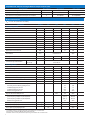
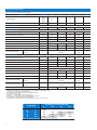
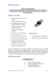
PRODUCT BRIEF
Intel® Ethernet QSFP+ Optics
Network Connectivity
Intel® Ethernet QSFP+ Optics
QSFP+ 40GBASE-SR4 Optics for Intel® Ethernet Converged Network Adapters
Key Features
• Support for 40GBASE Ethernet
•Maximum power dissipation < 1.5 W
•Hot-swappable 40 Gb I/O transceiver
that plugs into a QSFP+ port
•RoHS-6 compliant (lead-free)
•Supports the 4x10 GbE mode to
connect to four 10GBASE-SR optical
interfaces
•Four channel, full duplex transceiver
module
•Single 1x12 MPO receptacle
Overview
The Intel® Ethernet 40GBASE-SR4 QSFP+
Optics are available for customers who
would like to deploy Intel® Ethernet Converged Network Adapters with a QSFP+
SR optic. Intel® Ethernet Converged Network Adapters with QSFP+ connectivity
deliver proven, reliable solutions for
deployments of high density Ethernet
for unified 10GbE and 40GbE network
connections. Customers can move efficiently to 40GbE for high bandwidth
application requirements such as content
distribution, high-end virtualization using
multiple CPUs, network appliances, and
Applications Delivery Controllers (ACD)
used for content caching, load balancing,
•Commercial temperature range 0-70 °C
•Maximum link length 100m on OM3
MMF and 150m OM4 MMF
•1.06 Gb/s to 10.5 Gb/s per channel
multi-rate capability
•Compatible with Intel® Ethernet
Converged Network Adapters
and compression. To ensure maximum
flexibility, Intel supports the ability to use
any combination of Intel® Ethernet QSFP+
Optic, Intel® Ethernet QSFP+ Twinaxial
Cable, or Intel® Ethernet QSFP+ Breakout
Cable. This enables customers to create
the configuration that best meets the
needs of their data center environment,
while ensuring compatibility between
adapter and accessories.
General Specificatons
Module Form Factor
QSFP+
Network Standards Physical Layer Interface
• 40GBASE-SR4 (4x10GbE and 1x40GbE)
QSFP+ Module Specifications
• INF-8438i Specification for QSFP (Quad Small Form factor Pluggable) Transceiver
• SFF-8436 – Specification for QSFP+ Copper and Optical Transceiver
• IEEE 802.3ba – PMD Type 40GBASE-SR4
Number of Lanes
4 Tx and 4 Rx
Product Code
E40GQSFPSR
Compatible Intel® Ethernet Converged Network Adapters*
Intel® Ethernet Converged Network Adapter X520-QDA1
Intel® Ethernet Converged Network Adapter XL710-QDA1
Intel® Ethernet Converged Network Adapter XL710-QDA2
NOTE: Other brands of QSFP+ SR optical modules will not work with the Intel® Ethernet Converged Network Adapters.
NOTE: When two Intel® Ethernet Converged Network Adapter X520 and XL 710 Series QSFP+ devices are connected back to back, they should be configured with the
same Speed/Duplex setting. Results may vary if speed settings are mixed.
Compatible Intel® Ethernet Converged Network Adapter Product Codes
Configuration
No. of Ports
Single Pack
Bulk 5 Pack
Intel® Ethernet Converged Network Adapter X520-QDA1
1
X520QDA1
Intel® Ethernet Converged Network Adapter XL710-QDA1
1
XL710QDA1
XL710QDA1BLK
Intel® Ethernet Converged Network Adapter XL710-QDA2
2
XL710QDA2
XL710QDA2BLK
Optical Characteristics
(TOP = 0 °C to 70 °C, VCC=3.15 to 3.45 V)
Parameter
Symbol
Min
Typ
Max
Unit
Note
Gb/s
1
Transmitter (per Lane)
Signaling Speed per Lane
10.5
Center Wavelength
840
RMS Spectral Width
860
SW
Average Launch Power per Lane
Transmit OMA per Lane
Difference in Power between any two lanes (OMA)
Peek Power per Lane
TXPX
-7.6
TxOMA
-5.6
DPX
PPX
Launch Power (OMA) minus TDP per Lane
TDP per Lane
P-TDP
dBm
dB
4.0
dBm
12
> 86% at 19 um
< 30% at 4.5 um
RIN
(X1, X2, X3)
(Y1, Y2, Y3)
2
dBm
dB
Average launch power of OFF transmitter per lane
Transmitter eye mask definition
3.0
4.0
3.0
FLX
Reletive Intensity Noise
dBm
dBm
ORL
Encircled Flux
nm
-1.0
3.5
ER
Optical Return Loss Tolerance
0.65
-6.5
TDP
Optical Extinction Ratio
nm
dB
dBm
-30
dBm
-128
dB/Hz
0.23, 0.34, 0.43
0.27, 0.35, 0.4
Receiver (per Lane)
Signaling Speed per Lane
10.5
Center Wavelength
Damage Threshold
Average Receive Power per Lane
840
DT
3.4
RXPX
-9.5
GBd
860
nm
dBm
2.4
dBm
RxOMA
3.0
dBm
Stressed Reveiver Sensitivity (OMA) per Lane
SRS
-5.4
dBm
Peak Power per Lane
PPX
4
dBm
Receiver Reflectance
Rfl
-12
dB
1.9
0.3
0.47
-0.4
dB
UI
UI
dBm
-5.4
dBm
(75, 5)
(357, 1)
-0.4
KHz, UI
KHz, UI
dBm
-12
dBm
Receive Power (OMA) per Lane
Conditions of stressed receiver sensitivity test:
Vertical Eye Closure Penalty (VECP) per lane
Stressed eye J2 jitter per lane
Stressed eye J9 jitter per lane
OMA of each aggressor lane
Rx jitter tolerance in OMA per lane
Max
Conditions of receiver jitter tolerance test:
Jitter frequency and peak-to-peak amplitude
Jitter frequency and peak-to-peak amplitude
OMA of each aggressor lane
Loss of Optic Signal (LOS) De-Assert
LOSD
Loss of Optic Signal (LOS) Assert
LOSA
Loss of Optic Signal (LOS) Hysteresis
Notes:
1. Transmitter consists or four lasers operating at a maximum rate of 10.5 Gb/s each.
2. Even if TDP is < 0.9 dB, the OMA min must exceed this value.
3. Receiver consists of four photodetectors operating at a maximum rate of 10.5 Gb/s each.
2
-30
dBm
0.5
dBm
3
Electrical Characteristics
(TOP = 0 °C to 70 °C, VCC=3.15 to 3.45 V)
Parameter
Symbol
Min
Supply Voltage
Vcc1
VccTx
VccRx
3.15
Supply Current
Icc
Typ
Max
Unit
3.45
V
350
mA
2000
ms
4.0
V
1200
mVpp
Note
Link Turn-On Time
Transmit turn-on time
2
Transmitter (per Lane)
Single-ended input voltage tolerance
Differnential data input swing
VinT
-0.3
Vin,pp
180
Differnential input threshold
50
AC common mode input voltage tolerance (RMS)
15
Differential imput return loss
J2 Jitter Tolerance
J9 Jitter Tolerance
Data Dependent Pulse Width Shrinkage
Eye mask coordinates
mV
Per IEEE P802.3ba, Section 86A.4.1.1
dB
Jt2
0.17
UI
Jt9
0.29
UI
DDPWS
0.07
UI
(X1, X2)
(Y1, Y2)
3
mV
0.11, 0.31
95, 350
UI
mV
4
5
Receiver (per Lane)
Single-ended output voltage
Differnential data output swing
Vout,pp
-0.3
4.0
V
0
800
mVpp
7.5
mV
5
%
AC common mode output voltage (RMS)
Termination mismatch at 1 MHz
7, 8
Differnetial output return loss
Per IEEE P802.3ba, Section 86A.4.2.1
dB
4
Common mode output return loss
Per IEEE P802.3ba, Section 86A.4.2.2
dB
4
Output transition time, 20% to 80%
28
J2 Jitter output
ps
Jo2
J9 Jitter output
Jo9
0.42
UI
0.65
UI
Eye mask coordinates #1
(X1, X2)
(Y1, Y2)
0.29, 0.5
150, 425
UI
mV
6
Eye mask coordinates #2
(X1, X2)
(Y1, Y2)
0.29, 0.5
125, 500
UI
mV
5
Power Supply Ripple Tolerance
PSR
50
mVpp
Notes:
1. Maximum total power value is specified across the full temperature and voltage range.
2. From power-on and end of any fault conditions.
3. After internal AC coupling. Self-biasing 100 Ω differential input.
4. 10 MHz to 11.1 GHz range.
5. Hit ratio = 5 x 10E-5. Valid for all settings in Figure 1.
6. Hit ratio = 5 x 10E-5. Valid only for the shaded setting in Figure 1.
7. AC coupled with 100 Ω differential output impedence.
8. Settable in four diecrete steps via the I2C interface. See Figure 1 for Vout setting.
Volt (mV)
Power (mW)
Pre-Emphasis into 100 Ohms (mV)
0
0
599
317
751
125
175
325
935
971
1075
422
787
971
1007
1111
739
883
1055
1103
1190
Figure 1 - Power Dissipation (mW, maximum) vs. Rx Output Conditions
3
Regulatory Compliance
Customer Support
For Product Information
Transceivers are Class 1 Laser Products and
comply with US FDA regulations. These
products are certified to meet the Class 1
eye safety requirements of EN (IEC) 60825
and the electrical safety requirements
of EN (IEC) 60950. Copies of certificates
are available from Intel Corporation upon
request.
Intel® Customer Support Services offers
a broad selection of programs including
phone support and warranty service. For
more information, contact us at
www.intel.com/support.
To speak to a customer service representative regarding Intel products, please call
1-800-538-3373 (U.S. and Canada) or visit
www.intel.com/support/feedback.htm for
the telephone number in your area. For
additional product information on Intel®
Ethernet products, visit
www.intel.com/go/ethernet.
(Service and availability may vary
by country.)
By using this document, in addition to any agreements you have with Intel, you accept the terms set forth below.
You may not use or facilitate the use of this document in connection with any infringement or other legal analysis concerning Intel products described herein. You agree to grant Intel a nonexclusive, royalty-free license to any patent claim thereafter drafted which includes subject matter disclosed herein.
INFORMATION IN THIS DOCUMENT IS PROVIDED IN CONNECTION WITH INTEL PRODUCTS. NO LICENSE, EXPRESS OR IMPLIED, BY ESTOPPEL OR OTHERWISE, TO ANY INTELLECTUAL PROPERTY
RIGHTS IS GRANTED BY THIS DOCUMENT. EXCEPT AS PROVIDED IN INTEL’S TERMS AND CONDITIONS OF SALE FOR SUCH PRODUCTS, INTEL ASSUMES NO LIABILITY WHATSOEVER AND INTEL
DISCLAIMS ANY EXPRESS OR IMPLIED WARRANTY, RELATING TO SALE AND/OR USE OF INTEL PRODUCTS INCLUDING LIABILITY OR WARRANTIES RELATING TO FITNESS FOR A PARTICULAR
PURPOSE, MERCHANTABILITY, OR INFRINGEMENT OF ANY PATENT, COPYRIGHT OR OTHER INTELLECTUAL PROPERTY RIGHT.
A “Mission Critical Application” is any application in which failure of the Intel Product could result, directly or indirectly, in personal injury or death. SHOULD YOU PURCHASE OR USE INTEL’S
PRODUCTS FOR ANY SUCH MISSION CRITICAL APPLICATION, YOU SHALL INDEMNIFY AND HOLD INTEL AND ITS SUBSIDIARIES, SUBCONTRACTORS AND AFFILIATES, AND THE DIRECTORS, OFFICERS,
AND EMPLOYEES OF EACH, HARMLESS AGAINST ALL CLAIMS COSTS, DAMAGES, AND EXPENSES AND REASONABLE ATTORNEYS’ FEES ARISING OUT OF, DIRECTLY OR INDIRECTLY, ANY CLAIM OF
PRODUCT LIABILITY, PERSONAL INJURY, OR DEATH ARISING IN ANY WAY OUT OF SUCH MISSION CRITICAL APPLICATION, WHETHER OR NOT INTEL OR ITS SUBCONTRACTOR WAS NEGLIGENT IN THE
DESIGN, MANUFACTURE, OR WARNING OF THE INTEL PRODUCT OR ANY OF ITS PARTS.
Intel may make changes to specifications and product descriptions at any time, without notice. Designers must not rely on the absence or characteristics of any features or instructions marked
“reserved” or “undefined”. Intel reserves these for future definition and shall have no responsibility whatsoever for conflicts or incompatibilities arising from future changes to them. The
information here is subject to change without notice. Do not finalize a design with this information.
The products described in this document may contain design defects or errors known as errata which may cause the product to deviate from published specifications. Current characterized errata
are available on request.
Contact your local Intel sales office or your distributor to obtain the latest specifications and before placing your product order.
Copies of documents which have an order number and are referenced in this document, or other Intel literature, may be obtained by calling 1-800 548-4725, or go to: http://www.intel.com/design/
literature.htm
Copyright ©2014 Intel Corporation. All rights reserved. Intel, the Intel logo, NetEffect and Xeon are trademarks of Intel Corporation in the U.S. and
other countries.
*Other names and brands may be claimed as the property of others.
Printed in USA
LH/TAR/U/DMJ
Please Recycle
330381-001US