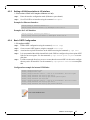
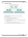
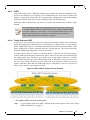
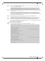
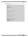
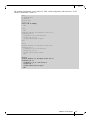
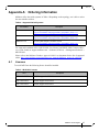
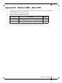
1
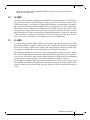
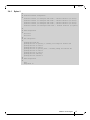
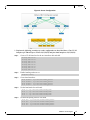
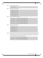
Mellanox Virtual Modular Switch™ Reference Guide Rev 1.2 www.mellanox.com Rev 1.2 NOTE: THIS HARDWARE, SOFTWARE OR TEST SUITE PRODUCT (“PRODUCT(S)”) AND ITS RELATED DOCUMENTATION ARE PROVIDED BY MELLANOX TECHNOLOGIES “AS-IS” WITH ALL FAULTS OF ANY KIND AND SOLELY FOR THE PURPOSE OF AIDING THE CUSTOMER IN TESTING APPLICATIONS THAT USE THE PRODUCTS IN DESIGNATED SOLUTIONS. THE CUSTOMER'S MANUFACTURING TEST ENVIRONMENT HAS NOT MET THE STANDARDS SET BY MELLANOX TECHNOLOGIES TO FULLY QUALIFY THE PRODUCTO(S) AND/OR THE SYSTEM USING IT. THEREFORE, MELLANOX TECHNOLOGIES CANNOT AND DOES NOT GUARANTEE OR WARRANT THAT THE PRODUCTS WILL OPERATE WITH THE HIGHEST QUALITY. ANY EXPRESS OR IMPLIED WARRANTIES, INCLUDING, BUT NOT LIMITED TO, THE IMPLIED WARRANTIES OF MERCHANTABILITY, FITNESS FOR A PARTICULAR PURPOSE AND NONINFRINGEMENT ARE DISCLAIMED. IN NO EVENT SHALL MELLANOX BE LIABLE TO CUSTOMER OR ANY THIRD PARTIES FOR ANY DIRECT, INDIRECT, SPECIAL, EXEMPLARY, OR CONSEQUENTIAL DAMAGES OF ANY KIND (INCLUDING, BUT NOT LIMITED TO, PAYMENT FOR PROCUREMENT OF SUBSTITUTE GOODS OR SERVICES; LOSS OF USE, DATA, OR PROFITS; OR BUSINESS INTERRUPTION) HOWEVER CAUSED AND ON ANY THEORY OF LIABILITY, WHETHER IN CONTRACT, STRICT LIABILITY, OR TORT (INCLUDING NEGLIGENCE OR OTHERWISE) ARISING IN ANY WAY FROM THE USE OF THE PRODUCT(S) AND RELATED DOCUMENTATION EVEN IF ADVISED OF THE POSSIBILITY OF SUCH DAMAGE. Mellanox Technologies 350 Oakmead Parkway Suite 100 Sunnyvale, CA 94085 U.S.A. www.mellanox.com Tel: (408) 970-3400 Fax: (408) 970-3403 Mellanox Technologies, Ltd. Beit Mellanox PO Box 586 Yokneam 20692 Israel www.mellanox.com Tel: +972 (0)74 723 7200 Fax: +972 (0)4 959 3245 © Copyright 2013. Mellanox Technologies. All Rights Reserved. Mellanox®, Mellanox logo, BridgeX®, ConnectX®, CORE-Direct®, InfiniBridge®, InfiniHost®, InfiniScale®, MLNX-OS®, PhyX®, SwitchX®, UFM®, Virtual Protocol Interconnect® and Voltaire® are registered trademarks of Mellanox Technologies, Ltd. Connect-IB™, FabricIT™, Mellanox Open Ethernet™, Mellanox Virtual Modular Switch™, MetroX™, MetroDX™, ScalableHPC™, Unbreakable-Link™ are trademarks of Mellanox Technologies, Ltd. All other trademarks are property of their respective owners. 2 Mellanox Technologies Document Number: 4087 Rev 1.2 Revision History Table 1 - Revision History Document Revision Rev 1.2 Date April 2014 Description Added: • • Rev 1.1 Dec 2013 Added: • • Rev. 1.0 July 2013 Chapter 5, “Multi Chassis LAG (MLAG)” on page 39 Chapter 6, “Multi Active Gateway Protocol (MAGP)” on page 44 Section 1.2, “L2 VMS,” on page 8 Chapter 3, “L2 VMS Configuration” on page 12 Initial release. Mellanox Technologies 3 Rev 1.2 About this Document This reference architecture provides general information concerning Mellanox Virtual Modular Switch™ configuration and design. Intended Audience This manual is intended for field engineers and network administrators intending to design a data center topology using Mellanox Ethernet switch platforms. Related Documentation The following table lists the documents referenced in this document. Table 2 - Reference Documents Document Name MLNX-OS® User Manual Description This document contains feature description and configuration flows. The document can be retrieved from Mellanox support page. Mellanox Ethernet Switch Systems Mellanox SX1016, SX1024, SX1036 The User Manual and Product brief can be retrieved here: http://www.mellanox.com/content/ pages.php?pg=ethernet_switch_overview&menu_section=71 Mellanox Technologies 4 Rev 1.2 Table of Contents Revision History . . . . . . . . . . . . . . . . . . . . . . . . . . . . . . . . . . . . . . . . . . . . . . . . . . . .3 About this Document . . . . . . . . . . . . . . . . . . . . . . . . . . . . . . . . . . . . . . . . . . . . . . . .4 Intended Audience . . . . . . . . . . . . . . . . . . . . . . . . . . . . . . . . . . . . . . . . . . . . . . .4 Related Documentation . . . . . . . . . . . . . . . . . . . . . . . . . . . . . . . . . . . . . . . . . . .4 Chapter 1 Introduction to Mellanox VMS. . . . . . . . . . . . . . . . . . . . . . . . . . . . . . . 7 1.1 Design Considerations . . . . . . . . . . . . . . . . . . . . . . . . . . . . . . . . . . . . . . . 7 1.2 L2 VMS . . . . . . . . . . . . . . . . . . . . . . . . . . . . . . . . . . . . . . . . . . . . . . . . . . . 8 1.3 L3 VMS . . . . . . . . . . . . . . . . . . . . . . . . . . . . . . . . . . . . . . . . . . . . . . . . . . . 8 Chapter 2 VMS Architecture . . . . . . . . . . . . . . . . . . . . . . . . . . . . . . . . . . . . . . . . . 9 2.1 2.2 2.3 2.4 Mellanox® VMS-72 (Entry Level) . . . . . . . . . . . . . . . . . . . . . . . . . . . . . . . 9 Scaling. . . . . . . . . . . . . . . . . . . . . . . . . . . . . . . . . . . . . . . . . . . . . . . . . . . . 9 Mellanox VMS-648 (Full Size) . . . . . . . . . . . . . . . . . . . . . . . . . . . . . . . . . 10 ToR Connectivity . . . . . . . . . . . . . . . . . . . . . . . . . . . . . . . . . . . . . . . . . . . 11 Chapter 3 L2 VMS Configuration . . . . . . . . . . . . . . . . . . . . . . . . . . . . . . . . . . . . 12 3.1 3.2 3.3 3.4 Prerequisites . . . . . . . . . . . . . . . . . . . . . . . . . . . . . . . . . . . . . . . . . . . . . . VLAN Configuration. . . . . . . . . . . . . . . . . . . . . . . . . . . . . . . . . . . . . . . . . MSTP Configuration . . . . . . . . . . . . . . . . . . . . . . . . . . . . . . . . . . . . . . . . VMS Switch Configuration Example . . . . . . . . . . . . . . . . . . . . . . . . . . . . 12 12 12 14 3.4.1 Spine-1 . . . . . . . . . . . . . . . . . . . . . . . . . . . . . . . . . . . . . . . . . . . . . . . . . . . 15 3.4.2 Spine-2 . . . . . . . . . . . . . . . . . . . . . . . . . . . . . . . . . . . . . . . . . . . . . . . . . . . 16 3.4.3 Leaf Configuration . . . . . . . . . . . . . . . . . . . . . . . . . . . . . . . . . . . . . . . . . . 17 3.5 VMS Server Configuration Example . . . . . . . . . . . . . . . . . . . . . . . . . . . . 17 3.6 Troubleshooting. . . . . . . . . . . . . . . . . . . . . . . . . . . . . . . . . . . . . . . . . . . . 21 Chapter 4 L3 VMS Configuration . . . . . . . . . . . . . . . . . . . . . . . . . . . . . . . . . . . . 23 4.1 Prerequisites . . . . . . . . . . . . . . . . . . . . . . . . . . . . . . . . . . . . . . . . . . . . . . 23 4.2 Common Procedures. . . . . . . . . . . . . . . . . . . . . . . . . . . . . . . . . . . . . . . . 23 4.2.1 4.2.2 4.2.3 4.2.4 Creating a VLAN Interface . . . . . . . . . . . . . . . . . . . . . . . . . . . . . . . . . . . . Creating a Static LAG. . . . . . . . . . . . . . . . . . . . . . . . . . . . . . . . . . . . . . . . Setting a VLAN Association to L2 interface . . . . . . . . . . . . . . . . . . . . . . . Basic OSPF Configuration . . . . . . . . . . . . . . . . . . . . . . . . . . . . . . . . . . . . 23 24 25 25 4.3 Configuration Example . . . . . . . . . . . . . . . . . . . . . . . . . . . . . . . . . . . . . . 26 4.3.1 4.3.2 4.3.3 4.3.4 4.3.5 4.3.6 Spine-1 . . . . . . . . . . . . . . . . . . . . . . . . . . . . . . . . . . . . . . . . . . . . . . . . . . . Spine-2 . . . . . . . . . . . . . . . . . . . . . . . . . . . . . . . . . . . . . . . . . . . . . . . . . . . Leaf-1 . . . . . . . . . . . . . . . . . . . . . . . . . . . . . . . . . . . . . . . . . . . . . . . . . . . . Leaf-2 . . . . . . . . . . . . . . . . . . . . . . . . . . . . . . . . . . . . . . . . . . . . . . . . . . . . Leaf-3 . . . . . . . . . . . . . . . . . . . . . . . . . . . . . . . . . . . . . . . . . . . . . . . . . . . . Leaf-4 . . . . . . . . . . . . . . . . . . . . . . . . . . . . . . . . . . . . . . . . . . . . . . . . . . . . 27 28 29 29 30 30 4.4 Advanced Considerations . . . . . . . . . . . . . . . . . . . . . . . . . . . . . . . . . . . . 30 4.4.1 Load Balancing. . . . . . . . . . . . . . . . . . . . . . . . . . . . . . . . . . . . . . . . . . . . . 30 4.4.2 56GbE Interface Rate. . . . . . . . . . . . . . . . . . . . . . . . . . . . . . . . . . . . . . . . 32 Mellanox Technologies 5 Rev 1.2 4.4.3 Store and Forward . . . . . . . . . . . . . . . . . . . . . . . . . . . . . . . . . . . . . . . . . . 33 4.4.4 OSPF . . . . . . . . . . . . . . . . . . . . . . . . . . . . . . . . . . . . . . . . . . . . . . . . . . . . 34 Chapter 5 Multi Chassis LAG (MLAG) . . . . . . . . . . . . . . . . . . . . . . . . . . . . . . . . 39 5.1 Topologies . . . . . . . . . . . . . . . . . . . . . . . . . . . . . . . . . . . . . . . . . . . . . . . . 39 5.2 MLAG Configuration . . . . . . . . . . . . . . . . . . . . . . . . . . . . . . . . . . . . . . . . 40 Chapter 6 Multi Active Gateway Protocol (MAGP) . . . . . . . . . . . . . . . . . . . . . . 44 Chapter 7 VMS Management. . . . . . . . . . . . . . . . . . . . . . . . . . . . . . . . . . . . . . . . 45 7.1 Automation Tools. . . . . . . . . . . . . . . . . . . . . . . . . . . . . . . . . . . . . . . . . . . 45 7.2 Network Discovery. . . . . . . . . . . . . . . . . . . . . . . . . . . . . . . . . . . . . . . . . . 45 Appendix A Ordering Information . . . . . . . . . . . . . . . . . . . . . . . . . . . . . . . . . . . .47 Appendix B Mellanox VMS – Basic POC . . . . . . . . . . . . . . . . . . . . . . . . . . . . . . .48 Mellanox Technologies 6 Rev 1.2 1 Introduction to Mellanox VMS As new applications are being constantly developed, data centers must be flexible and futureproof to meet the demand for higher throughput and better scalability, while protecting the investment, without increasing the power consumption or cost. Traditionally, cloud providers, Web 2.0 providers and enterprises use modular based aggregation switches in their data centers. These switches, usually expensive to purchase and operate and optimized for specific cluster sizes, do not provide the required flexibility and tend to lag behind the progress of data center technologies. To overcome this limitation, more fixed switches (or top-of-rack switches) are used to increase efficiency in data center aggregation. The Mellanox Virtual Modular Switch™ solution (VMS), comprised of Mellanox® SX1036 switch systems, provides an ideal optimized approach for new levels of flexibility, scalability and efficiency, while future-proofing the investment and reducing expenses. This document presents Mellanox VMS topology and configuration and offers a set of guidelines for advanced users both with a standard layer 3 based VMS and a standard layer 2 based VMS. Naturally, network designers may find it necessary to apply some topology modifications to better suit their needs and are eligible to choose either the layer 2 variant or the layer 3 variant of the VMS, according to their professional preference and network needs. 1.1 Design Considerations Each data center has its own characteristics and needs. Generally, when designing a large data center network, it is essential to consider the following variables: • Interface rate – server clusters may be comprised of tens of thousands of ports, thus requiring high-performance packet switching, large bandwidth, and high port speeds. Server interfaces are moving away from 1GbE to 10GbE and 40GbE. Beyond the standard 10GbE and 40GbE link rates, Mellanox systems also offer a 56GbE proprietary speed that reduces costs and rack space in the data center. • Number of servers – the number of servers (overall and per rack) multiplied by the interface rate gives the north-bound throughput of the ToR. The number of servers per rack is normally 40. • Oversubscription ratio – data center applications may require different oversubscription ratios. North-South traffic and East-West traffic have different characteristics according to the network application. Also, non-blocking or any blocking ratio is possible. The oversubscription ratio must be examined at multiple aggregation points of East-West and North-South traffic. • Latency – latency affects the overall performance of the cluster. Using Mellanox lowlatency switch platforms helps to ensure optimal performance. However, low-latency may not always be a critical factor in the cluster design. Certain applications might prioritize bandwidth over latency, which might impact topology decisions when designing the network. • Switching and routing - data centers can design to operate on either a layer 2 or a layer 3 network. Most common implementations today are based on layer 3 routing protocols such as OSPF as described in this paper but others might prefer to extend their layer 2 domain from the rack level to the data center level. Technologies such as overlay networks (VXLAN, NVGRE) or RDMA over Converged Ethernet version 2 (RoCEv2) Mellanox Technologies 7 Rev 1.2 enable the layer 3 networks with further capabilities which were previously limited to a single layer 2 domain only. 1.2 L2 VMS L2 VMS is based on Ethernet configuration and MSTP. The distribution leans on the MSTP protocol, where the number of MSTP instances is equal (or greater) to the number of spines in the VMS and each spine is a root bridge of a different MSTP instance. In such topology, load balancing is achieved between the different MSTP instances and triggered by the server applications. Each instance creates a different tree to a different set of VLANs. This way, a part of the VLANs will pass from one spine, another part of the VLANs will pass from another spine and so on. Note that if the number of VLANs in your network is smaller than the number of spines, the utilization of the VMS will not be efficient. For example, in case there is only one VLAN, only one spine can be used. The rest of the spines will be alternative routes for the MSTP tree. 1.3 L3 VMS L3 VMS is based on IP and OSPF configuration. The IP network topology is discovered via the Open Shortest Path First (OSPF) routing protocol that is enabled on all ToR and aggregation devices in the network. OSPF routers exchange link status messages with their physical neighbors in order to establish the same network topology for all routers in the network. The mechanism enabling the selection of several routes (dynamic routing) to the same destination is called ECMP (equal cost multi-path). Without ECMP, the router selects the best equal cost route and uses it as the only path to the destination IP address. ECMP can also be implemented over static routes as long as all routes to the same destination are indeed of equal cost. The advantage of running ECMP with a routing protocol such as OSPF is that it supplies good and redundant load balancing. OSPF handles the dynamic learning of the network and the active routes are pushed into the routing table, while the ECMP does the load balancing between the routes. Mellanox Technologies 8 Rev 1.2 2 VMS Architecture The VMS principal topology is a CLOS-3 that consists of a fat tree (multi-root tree) of routing elements (leafs and spines). Each of the leafs needs to physically connect to each of the spines in order to guarantee exactly two hops between any two leafs. The multiple routes between the leafs have the same weight and receive the same priority in each of the routing tables. The topologies lean on non-blocking architecture design between the leafs and spines of the VMS. 2.1 Mellanox® VMS-72 (Entry Level) Mellanox’s VMS-72 (72 ports) is illustrated in the following diagram. It is a typical entry level VMS topology. It can be used for small-scale clusters or as a starting point for large scale clusters. Mellanox’s VMS-72 is equipped with 2 spines and 4 leafs. In addition, up to 18 ToR switches can be connected to the VMS assuming each ToR has 4x40GbE uplink ports configured as 2x40GbE LAG for each leaf. Figure 1: Entry Level VMS Mellanox VMS – Entry Level SX1036 SX1036 9x40GbE SX1036 SX1036 SX1036 SX1036 2x40GbE 2.2 ToR ToR ToR ToR ToR ToR ToR ToR ToR ToR ToR ToR ToR ToR ToR ToR ToR ToR Rack Rack Rack Rack Rack Rack Rack Rack Rack Rack Rack Rack Rack Rack Rack Rack Rack Rack Scaling The VMS scales easily by adding spine and leaf switches. The minimal number of switches required for each expansion are one spine and two leafs that add 36 extra ports to the VMS. Best-practice VMS scaling sizes are described in Table 3. Other VMS designs are possible but must be thought through carefully as it may cause asymmetry within the VMS. Table 3 - Best Practice of Mellanox VMS Size Mellanox VMS Number of Spines Number of Leafs Link Size between a Leaf and a Spine Mellanox VMS-72 2 4 9x40GbE Mellanox VMS-108 3 6 6x40GbE Mellanox VMS-216 6 12 3x40GbE Mellanox Technologies 9 Rev 1.2 Table 3 - Best Practice of Mellanox VMS Size Mellanox VMS Number of Spines Link Size between a Leaf and a Spine Number of Leafs Mellanox VMS-324 9 18 2x40GbE Mellanox VMS-648 18 36 1x40GbE Figure 2: VMS Scaling Mellanox VMS – Scaling SX1036 SX1036 SX1036 6x40GbE SX1036 2.3 SX1036 SX1036 SX1036 SX1036 SX1036 ToR ToR ToR ToR ToR ToR ToR ToR ToR ToR ToR ToR ToR ToR ToR ToR ToR ToR ToR ToR ToR ToR ToR ToR ToR ToR ToR Rack Rack Rack Rack Rack Rack Rack Rack Rack Rack Rack Rack Rack Rack Rack Rack Rack Rack Rack Rack Rack Rack Rack Rack Rack Rack Rack Mellanox VMS-648 (Full Size) Mellanox VMS-648 (648 ports) is illustrated in the following diagram. It is a typical full-scale VMS topology. It is meant to be used for large clusters. Mellanox VMS-648 is equipped with 18 spines and 36 leafs. In addition, up to 162 ToR switches (9 ToR switches * 18 leaf pairs) may be connected to the VMS assuming each ToR has 4x40GbE uplink ports configured as 2x40GbE LAG for each leaf. Figure 3: Full Size VMS Mellanox VMS – Full size SX1036 18 Spines SX1036 SX1036 1x40GbE SX1036 SX1036 SX1036 SX1036 SX1036 36 Leafs SX1036 ToR ToR ToR ToR ToR ToR ToR ToR ToR ToR ToR ToR ToR ToR ToR ToR ToR ToR ToR ToR ToR ToR ToR ToR ToR ToR ToR Rack Rack Rack Rack Rack Rack Rack Rack Rack Rack Rack Rack Rack Rack Rack Rack Rack Rack Rack Rack Rack Rack Rack Rack Rack Rack Rack ... Mellanox Technologies 10 Rev 1.2 2.4 ToR Connectivity Typical ToR connectivity in the Mellanox VMS is 4x40GbE to two leafs. The link is divided to 2x40GbE per leaf switch configured as LAG. Additional configuration options are possible according to the data center’s needs (for example, using a different number of links between the ToR and the leafs, or not using a high availability configuration scheme). Figure 4: ToR Connectivity Leaf Leaf 2x40GbE ToR ToR ToR ToR ToR ToR ToR ToR ToR Rack Rack Rack Rack Rack Rack Rack Rack Rack Mellanox Technologies 11 Rev 1.2 3 L2 VMS Configuration Once the Mellanox® VMS topology is defined, network configuration must be applied to the VMS. Mellanox VMS can run in L2 mode with MSTP configured in the switches. This solution is suitable for setups where the number of VLANs is equal or higher than the number of VMS spines. This way, the traffic can be load balanced along the spines This solution achieves the following High Availability (HA) options: 3.1 • Adapter card HA: Achieved when configuring bond interfaces (link aggregation) on the server. • ToR/Leaf HA: If one ToR/Leaf is down, the traffic will be sent via a secondary link from the server to another switch. • Spine HA: If one spine is down, another spine will be elected to be the MSTP root for that MSTP instance. Prerequisites Before attempting to configure a switch within the Mellanox VMS, make sure the following conditions are met: 3.2 • The switch system is up and has a management IP address. • The system profile is: eth-single-switch. Use the command show system profile to verify this. • The Mellanox OS switch management software version is 3.3.4300 or higher. VLAN Configuration All internal VMS ports should be set to switchport type “trunk”. In addition, all the VLANs in the network should be mapped to those ports. To set switch porttype, perform the following steps: Step 1. Enter to config interface configuration mode. Step 2. Set the switchport type to trunk. switch (config)# interface ethernet 1/1 switch (config interface ethernet 1/1)# switchport mode trunk Step 3. Create a VLAN (for each active VLAN in your network). switch (config)# vlan 10 switch (config vlan 10)# exit Step 4. Assign all switch VLANs to all internal VMS ports. For example, assuming ethernet 1/1 of a leaf switch is connected to the spine switch, perform the following: switch (config)# interface ethernet 1/1 switch (config interface ethernet 1/1)# switchport trunk allowed-vlan all 3.3 MSTP Configuration To set MSTP global parameters on the switch, perform the following steps: Step 1. Set MSTP as the spanning tree switch mode. Mellanox Technologies 12 Rev 1.2 Step 2. Set the MSTP revision. Note that the MSTP revision must be the same throughout the MSTP subnet. Step 3. Set the MSTP name. Note that the MSTP name must be the same throughout the MSTP subnet. switch (config)# spanning-tree mode mst switch (config)# spanning-tree mst name mstp switch (config)# spanning-tree mst revision 1 Step 4. Add each VLAN to an MSTP instance. Note that the number of instances in your network should be equal to the number of spines you have. It is possible to add up to 64 VLANs per MSTP instance. The following configuration should be done for all VMS switches. switch switch switch switch Step 5. (config)# (config)# (config)# (config)# spanning-tree spanning-tree spanning-tree spanning-tree mst mst mst mst 10 10 20 20 vlan vlan vlan vlan 10 11 20 21 MSTP instance priority must be configured per MSTP instance only in the spine switches. Each spine should be a root bridge for one MSTP instance and a secondary root for the rest of the instances. For example, assume VMS-72 has 2 spines and two instances, #10 and #20 (as shown above). One spine must be a root bridge for MSTP instance #10 and a secondary root for MSTP instance #20, and the other switch must be a root bridge for VLAN #20 and a secondary root for MSTP instance #10. This is achieved by setting the MSTP bridge priority First spine configuration example for VMS-72: switch (config)# spanning-tree mst 10 priority 0 // root bridge for instance #10 switch (config)# spanning-tree mst 20 priority 4096 // secondary root bridge Second spine configuration example for VMS-72: switch (config)# spanning-tree mst 20 priority 0 // root bridge for instance #20 switch (config)# spanning-tree mst 0 priority 4096 // secondary root bridge Mellanox Technologies 13 Rev 1.2 3.4 VMS Switch Configuration Example Figure 5: VMS-72 Configuration Example - L2 MSTP Mellanox Technologies 14 Rev 1.2 3.4.1 Spine-1 ## ## Interface ## interface interface interface interface interface Ethernet configuration ethernet ethernet ethernet ethernet ethernet 1/1 switchport mode trunk // Internal interface (to Leaf-1) 1/2 switchport mode trunk // Internal interface (to Leaf-2) 1/3 switchport mode trunk // Internal interface (to Leaf-3) 1/4 switchport mode trunk // Internal interface (to Leaf-4) 1/36 switchport mode trunk // Internal interface (to Spine-2) ## ## VLAN configuration ## vlan 10-11 vlan 20-21 ## ## STP configuration ## spanning-tree mode mst spanning-tree mst 10 priority 0 //Primary root bridge for Instance #10 spanning-tree mst 10 vlan 10 spanning-tree mst 10 vlan 11 spanning-tree mst 20 priority 4096 // Secondary bridge for Instance #20 spanning-tree mst 20 vlan 20 spanning-tree mst 20 vlan 21 spanning-tree mst name mstp spanning-tree mst revision 1 ## ## LLDP configuration ## lldp lldp reinit 10 Mellanox Technologies 15 Rev 1.2 3.4.2 Spine-2 ## ## Interface ## interface interface interface interface interface Ethernet configuration ethernet ethernet ethernet ethernet ethernet 1/1 switchport mode trunk // Internal interface (to Leaf-1) 1/2 switchport mode trunk // Internal interface (to Leaf-2) 1/3 switchport mode trunk // Internal interface (to Leaf-3) 1/4 switchport mode trunk // Internal interface (to Leaf-4) 1/36 switchport mode trunk // Internal interface (to Spine-1) ## ## VLAN configuration ## vlan 10-11 vlan 20-21 ## ## STP configuration ## spanning-tree mode mst spanning-tree mst 10 priority 4094 //Secondary root bridge for Instance #10 spanning-tree mst 10 vlan 10 spanning-tree mst 10 vlan 11 spanning-tree mst 20 priority 0 // Primary bridge for Instance #20 spanning-tree mst 20 vlan 20 spanning-tree mst 20 vlan 21 spanning-tree mst name mstp spanning-tree mst revision 1 ## ## LLDP configuration ## lldp lldp reinit 10 Mellanox Technologies 16 Rev 1.2 3.4.3 Leaf Configuration The following configuration is similar in all leaf switches. ## ## Interface ## interface interface interface Ethernet configuration ethernet 1/1 switchport mode trunk // Internal interface (to Spine-1) ethernet 1/2 switchport mode trunk // Internal interface (to Spine-2) ethernet 1/36 switchport mode trunk // External interface (ToR/Server) ## ## VLAN configuration ## vlan 10-11 vlan 20-21 ## ## STP configuration ## spanning-tree mode mst spanning-tree mst 10 vlan 10 spanning-tree mst 10 vlan 11 spanning-tree mst 20 vlan 20 spanning-tree mst 20 vlan 21 spanning-tree mst name mstp spanning-tree mst revision 1 ## ## LLDP configuration ## lldp lldp reinit 10 3.5 VMS Server Configuration Example For High Availability, it is recommended to have two Mellanox ConnectX-3/ConnectX-3 Pro adapter cards installed in each server, and two network interfaces of the same VLAN configured as a bond (link aggregation). Each interface should be connected to a different leaf in the VMS. Mellanox Technologies 17 Rev 1.2 Figure 6: Server Configuration Perform the following procedure to set the configuration as described above. Four VLAN interfaces per Ethernet port (VLANs 10,11,20,12) and four bond interfaces (10,11,20,21): Step 1. Create a VLAN interface for the two interfaces eth1 and eth2. #vconfig #vconfig #vconfig #vconfig #vconfig #vconfig #vconfig #vconfig Step 2. add add add add add add add add eth1 eth1 eth1 eth1 eth2 eth2 eth2 eth2 10 11 20 21 10 11 20 21 Enable bonding on the server. #modprobe bonding Step 3. Create bond interfaces. #echo #echo #echo #echo Step 4. > > > > /sys/class/net/bonding_masters /sys/class/net/bonding_masters /sys/class/net/bonding_masters /sys/class/net/bonding_masters Set the bond mode for each bond. #echo #echo #echo #echo Step 5. +bond10 +bond11 +bond20 +bond21 1 1 1 1 > > > > /sys/class/net/bond10/bonding/mode /sys/class/net/bond11/bonding/mode /sys/class/net/bond20/bonding/mode /sys/class/net/bond21/bonding/mode Set the bond polling time for each bond. #echo #echo #echo #echo 100 100 100 100 > > > > /sys/class/net/bond10/bonding/miimon /sys/class/net/bond11/bonding/miimon /sys/class/net/bond20/bonding/miimon /sys/class/net/bond21/bonding/miimon Mellanox Technologies 18 Rev 1.2 Step 6. Enable the physical interfaces. # ifconfig eth1 up # ifconfig eth2 up Step 7. Disable the VLAN interfaces. # # # # # # # # Step 8. eth1.10 eth1.11 eth1.20 eth1.21 eth2.10 eth2.11 eth2.20 eth2.21 down down down down down down down down Add two interfaces for each bond. # # # # # # # # Step 9. ifconfig ifconfig ifconfig ifconfig ifconfig ifconfig ifconfig ifconfig echo echo echo echo echo echo echo echo +eth1.10 +eth2.10 +eth1.11 +eth2.11 +eth1.20 +eth2.20 +eth1.21 +eth2.21 > > > > > > > > /sys/class/net/bond10/bonding/slaves /sys/class/net/bond10/bonding/slaves /sys/class/net/bond11/bonding/slaves /sys/class/net/bond11/bonding/slaves /sys/class/net/bond20/bonding/slaves /sys/class/net/bond20/bonding/slaves /sys/class/net/bond21/bonding/slaves /sys/class/net/bond21/bonding/slaves Enable the VLAN interfaces. # # # # # # # # ifconfig ifconfig ifconfig ifconfig ifconfig ifconfig ifconfig ifconfig eth1.10 eth1.11 eth1.20 eth1.21 eth2.10 eth2.11 eth2.20 eth2.21 up up up up up up up up Step 10. Set the primary interface for each VLAN. For better utilization of the fabric, select half of the VLANs to egress via eth1 interface and the second half via eth2 interface. This operation utilizes both ports at the same time. In the example below, VLAN10 and VLAN 11 egress via eth1, while VLAN20 and VLAN21 egress via eth2. #echo #echo #echo #echo eth1.10 eth1.11 eth2.20 eth2.21 > > > > /sys/class/net/bond10/bonding/primary /sys/class/net/bond11/bonding/primary /sys/class/net/bond20/bonding/primary /sys/class/net/bond21/bonding/primary Mellanox Technologies 19 Rev 1.2 Step 11. To display the bond configuration, use the following command. #cat /proc/net/bonding/bond10 Ethernet Channel Bonding Driver: v3.6.0 (September 26, 2009) Bonding Mode: fault-tolerance (active-backup) Primary Slave: eth1.100 (primary_reselect always) Currently Active Slave: eth1.10 MII Status: up MII Polling Interval (ms): 100 Up Delay (ms): 0 Down Delay (ms): 0 Slave Interface: eth1.10 MII Status: up Speed: 40000 Mbps Duplex: full Link Failure Count: 0 Permanent HW addr: 00:02:c9:a0:aa:41 Slave queue ID: 0 Slave Interface: eth2.10 MII Status: up Speed: 40000 Mbps Duplex: full Link Failure Count: 0 Permanent HW addr: 00:02:c9:ef:f4:e2 Slave queue ID: 0 Step 12. To test this setup, simply configure an IP address for each bond, or connect the bond to a VM interface via macvtap interface, and ping another server in your network. //Server-1 # ifconfig bond10 11.11.10.1/24 up # ifconfig bond11 11.11.11.1/24 up # ifconfig bond20 11.11.20.1/24 up # ifconfig bond21 11.11.21.1/24 up //Server-2 # ifconfig bond10 11.11.10.2/24 up # ifconfig bond11 11.11.11.2/24 up # ifconfig bond20 11.11.20.2/24 up # ifconfig bond21 11.11.21.2/24 up //Server-1 # ping 11.11.10.2 PING 11.11.11.2 (11.11.11.2) 56(84) bytes of data. 64 bytes from 11.11.11.2: icmp_seq=1 ttl=64 time=0.998 ms 64 bytes from 11.11.11.2: icmp_seq=2 ttl=64 time=0.157 ms 64 bytes from 11.11.11.2: icmp_seq=3 ttl=64 time=0.160 ms # At this step, traffic from bond 10 and 11 passes via Spine-1 while traffic from bond 20 and 21 passes via Spine-2 Mellanox Technologies 20 Rev 1.2 3.6 Troubleshooting Troubleshooting network problems could be a hard task. However, if you split the problem to several small verification tasks, it becomes easier. Ping is not running between two servers on the same VLAN. Perform the following tests: Step 1. Verify that L2 connectivity is correct. All ports are connected to the right ports within the VMS. To do that, it is recommended to enable LLDP in each switch for easy discovery. Use the switch command show lldp interfaces remote to see all remote information in every switch. For a large-sized VMS, you can use an LLDP script for discovery or other standard network discovery tools. switch (config) # show lldp interfaces ethernet remote Eth1/1 Remote Remote Remote Remote Remote Remote Remote Remote ... switch Step 2. Index: 2 chassis id: 00:02:c9:72:9c:f0 ; chassis id subtype: Mac Address (4) port-id: Eth1/1 ; port id subtype: Interface Name (5) port description: N\A system name: r-qa-sit-sx05 system description: Mellanox SX6036,MLNX-OS,SWvSX_3.3.4204 system capabilities supported: B,R ; enabled B Management Address: 10.209.28.81 (config)# Verify that all relevant ports are up. Run the command show internet status. switch (config) # r-qa-sit-sx01 (config) # show interfaces ethernet status Port ---Eth1/1 Eth1/2 .... Operational state ----------------Up Up Speed ----40 Gbps 40 Gbps Negotiation ----------No-Negotiation No-Negotiation switch (config)# Step 3. Verify that all ports are in trunk mode, and all VLANs are allowed over the trunk links. Use the command show interfaces switchport. switch (config) # show interfaces switchport Interface | Mode | Access vlan | Allowed vlans -----------|------------|-------------|--------------------------Eth1/1 trunk N/A 1, 10, 11, 20, 21 Eth1/2 trunk N/A 1, 10, 11, 20, 21 switch (config) # Step 4. Verify MSTP configuration. • Make sure that each spine is the root bridge of the right MSTP instance. • Make sure that the right VLANs are attached to the relevant MSTP instance. • Make sure that the MSTP name and revision are the same across the VMS. Mellanox Technologies 21 Rev 1.2 • Use the command show spanning-tree mst details. switch (config) # show spanning-tree mst details Global Configuration Revision:1 Max-hops:20 Name:mstp MST0 vlans mapped: 1-9,12-19,22-1024,1025-2048,2049-3072,3073-4094 Bridge address f4:52:14:11:e5:30 priority 32768 Root address 00:02:c9:60:dc:e0 priority 32768 Operational Hello time 2 , forward delay 15 , max-age 20 Configured Hello time 2 , forward delay 15 , max-age 20 Interface Role Sts Cost Prio ----------------Eth1/1 Root Forwarding 500 128.1 Eth1/2 Alternate Discarding 500 128.2 Eth1/36 Designated Forwarding 500 128.36 MST10 vlans mapped: 10-11 Bridge address f4:52:14:11:e5:30 priority 32768 Root address 00:02:c9:72:9c:f0 priority 0 Interface Role Sts ----------Eth1/1 Root Forwarding Eth1/2 Alternate Discarding Eth1/36 Designated Forwarding N/A 1, 10, 11, 20, 21 ... switch (config) # Step 5. Step 6. Cost ---500 500 500 Prio ---128.1 128.2 128.36 Type ---point-to-point point-to-point point-to-point Type ---point-to-point point-to-point point-to-point Verify that the server configuration is correct. • Make sure that all interfaces (ethernet, VLANs and bonds) are in Up state. • Make sure that the bonds are configured correctly. • Check the routing table within the server. Follow the trace of a single packet, use the command show mac-address-table on every switch on the path and verify that the mac-address table entries meet your expectations. Mellanox Technologies 22 Rev 1.2 4 L3 VMS Configuration Once the Mellanox® VMS topology is defined, network configuration must be applied to the VMS. 4.1 Prerequisites Before attempting to configure a switch within the Mellanox VMS, make sure the following conditions are met: 4.2 • The switch system is up and has a management IP address • The system profile is: eth-single-switch. Use the command show system profile to verify this. Common Procedures This section describes the following set of basic common procedures: 4.2.1 • “Creating a VLAN Interface” • “Creating a Static LAG” • “Setting a VLAN Association to L2 interface” • “Basic OSPF Configuration” Creating a VLAN Interface To create a VLAN interface (IP interface): Step 1. Create a VLAN using the command vlan <vlan-id>. Step 2. Attach at least one interface to this VLAN. Run the command switchport in the interface configuration mode. There must be at least one interface in the operational state “up”. Step 3. Create a VLAN interface using the command interface vlan. Step 4. Set an IP address and subnet mask for this interface. Example: switch switch switch switch switch switch switch state (config)# vlan 10 (config vlan 10)# exit (config)# interface ethernet 1/1 (config interface ethernet 1/1)# switchport mode access (config interface ethernet 1/1)# switchport access vlan 10 (config interface ethernet 1/1)# exit (config)# show interface etherent status // ensuring there is a port in UP Mellanox Technologies 23 Rev 1.2 Port ---Eth1/1 … Operational state ----------------Up Speed ----40 Gbps Negotiation ----------No-Negotiation switch (config)#interface vlan 10 switch (config interface vlan)#ip address 10.10.10.10 /24 switch (config interface vlan)#show interface vlan 10 Vlan 10 Admin state: Enabled Operational state: UP Mac Address: 00:02:c9:5d:e0:f0 Internet Address: 10.10.10.10/24 Broadcast address: 10.10.10.255 MTU: 1500 bytes Description: my-ip-interface Counters: disabled switch (config interface vlan)# 4.2.2 Creating a Static LAG To create a static LAG: Step 1. Create a port-channel (LAG) using the command interface port-channel. Step 2. Add physical interfaces to the port-channel group using the command channel-group in the interface configuration mode. Optionally, LACP may be enabled. Refer to MLNX-OS® User Manual (Link Aggregation Group chapter), for more information. Example: switch switch switch switch switch switch (config) # vlan 10 // creating a vlan (if nonexistent) (config vlan 10) exit (config) # interface port-channel 1 (config interface port-channel 1) #exit (config) # interface ethernet 1/1 (config interface ethernet 1/1) # channel-group 1 mode on // static LAG If the physical port is operationally up, this port becomes an active member of the aggregation. Consequently, it becomes able to convey traffic. Mellanox Technologies 24 Rev 1.2 4.2.3 Setting a VLAN Association to L2 interface To associate a VLAN to L2 interface (Ethernet or LAG): Step 1. Enter the interface configuration mode (Ethernet or port-channel) Step 2. Set a VLAN ID to an interface using the command switchport. Example for Ethernet Interface: switch (config) # interface ethernet 1/1 switch (config interface ethernet 1/1) #switchport access vlan 10 Example: for LAG Interface: switch (config) # interface port-channel 1 switch (config interface port-channel 1) #switchport access vlan 10 4.2.4 Basic OSPF Configuration To configure OSPF: Step 1. Enable OSPF configuration using the command protocol ospf, Step 2. Create a router OSPF instance using the command router ospf. Step 3. Associate the required IP interfaces to the OSPF area using the command ip ospf area. Step 4. It is recommended that all the internal links in the VMS are configured as point-to-point OSPF links for fast convergence. Use the command ip ospf network point-to-point to accomplish that. Step 5. For links connected directly to servers or routers that do not run OSPF it is advised to configure them as passive IP interfaces. Use the command ip ospf passive-interface to accomplish that. Configuration example for internal VMS links: switch switch switch switch switch switch switch switch switch (config)# protocol ospf (config)# router ospf (config)# interface vlan 10 (config interface vlan 10)# (config interface vlan 10)# (config interface vlan 10)# (config)# interface vlan 20 (config interface vlan 20)# (config interface vlan 20)# // Vlan ip ospf ip ospf exit // Vlan ip ospf ip ospf 10 is used between a leaf and a spine area 0 network point-to-point 20 is used between a leaf and a server area 0 passive-interface Area 0 is the backbone area. Mellanox Technologies 25 Rev 1.2 4.3 Configuration Example Figure 7: VMS-72 Configuration Example - L3 The following steps provide an initial configuration flow necessary on each VMS switch. To configure the VMS: Step 1. Ensure the prerequisites are met. Refer to Section 4.1, “Prerequisites,” on page 23. Step 2. Disable spanning-tree using the command no spanning-tree. Step 3. (Recommended) Enable LLDP. use the command lldp. Step 4. (Optional) For each IP interface, configure the link as a LAG. Refer to Section 4.2.2, “Creating a Static LAG,” on page 24. Step 5. Set a VLAN for each L2 interface. Refer to Section 4.2.3, “Setting a VLAN Association to L2 interface,” on page 25. Step 6. Create a VLAN interface (with the same VLAN used in the previous step) for each IP interface. Refer to Section 4.2.1, “Creating a VLAN Interface,” on page 23. Step 7. Enable OSPF on the ToR. Refer to Section 4.2.4, “Basic OSPF Configuration,” on page 25. Mellanox Technologies 26 Rev 1.2 4.3.1 Spine-1 lldp no spanning-tree ip routing protocol ospf router ospf exit vlan 1 exit interface ethernet 1/1 switchport access vlan 1 interface vlan 1 ip address 11.11.1.2 255.255.255.0 ip ospf area 0.0.0.0 ip ospf network point-to-point exit vlan 2 exit interface ethernet 1/2 switchport access vlan 2 interface vlan 2 ip address 11.11.2.2 255.255.255.0 ip ospf area 0.0.0.0 ip ospf network point-to-point exit vlan 3 exit interface ethernet 1/3 switchport access vlan 3 interface vlan 3 ip address 11.11.3.2 255.255.255.0 ip ospf area 0.0.0.0 ip ospf network point-to-point exit vlan 4 exit interface ethernet 1/4 switchport access vlan 4 interface vlan 4 ip address 11.11.4.2 255.255.255.0 ip ospf area 0.0.0.0 ip ospf network point-to-point exit Mellanox Technologies 27 Rev 1.2 4.3.2 Spine-2 lldp no spanning-tree ip routing protocol ospf router ospf exit vlan 5 exit interface ethernet 1/1 switchport access vlan 5 interface vlan 5 ip address 11.11.5.2 255.255.255.0 ip ospf area 0.0.0.0 ip ospf network point-to-point exit vlan 6 exit interface ethernet 1/2 switchport access vlan 6 interface vlan 6 ip address 11.11.6.2 255.255.255.0 ip ospf area 0.0.0.0 ip ospf network point-to-point exit vlan 7 exit interface ethernet 1/3 switchport access vlan 7 interface vlan 7 ip address 11.11.7.2 255.255.255.0 ip ospf area 0.0.0.0 ip ospf network point-to-point exit vlan 8 exit interface ethernet 1/4 switchport access vlan 8 interface vlan 8 ip address 11.11.8.2 255.255.255.0 ip ospf area 0.0.0.0 ip ospf network point-to-point exit Mellanox Technologies 28 Rev 1.2 4.3.3 Leaf-1 lldp no spanning-tree ip routing protocol ospf router ospf exit vlan 1 exit interface ethernet 1/1 switchport access vlan 1 interface vlan 1 ip address 11.11.1.1 255.255.255.0 ip ospf area 0.0.0.0 ip ospf network point-to-point exit vlan 5 interfac ethernet 1/2 switchport access vlan 5 interface vlan 5 ip address 11.11.5.1 255.255.255.0 ip ospf area 0.0.0.0 ip ospf network point-to-point exit 4.3.4 Leaf-2 lldp no spanning-tree ip routing protocol ospf router ospf exit vlan 2 exit interface ethernet 1/1 switchport access vlan 2 interface vlan 2 ip address 11.11.2.1 255.255.255.0 ip ospf area 0.0.0.0 ip ospf network point-to-point exit vlan 6 interfac ethernet 1/2 switchport access vlan 6 interface vlan 6 ip address 11.11.6.1 255.255.255.0 ip ospf area 0.0.0.0 ip ospf network point-to-point exit Mellanox Technologies 29 Rev 1.2 4.3.5 Leaf-3 lldp no spanning-tree ip routing protocol ospf router ospf exit vlan 3 exit interface ethernet 1/1 switchport access vlan 3 interface vlan 3 ip address 11.11.3.1 255.255.255.0 ip ospf area 0.0.0.0 ip ospf network point-to-point exit vlan 7 interfac ethernet 1/2 switchport access vlan 7 interface vlan 7 ip address 11.11.7.1 255.255.255.0 ip ospf area 0.0.0.0 ip ospf network point-to-point exit 4.3.6 Leaf-4 lldp no spanning-tree ip routing protocol ospf router ospf exit vlan 4 exit interface ethernet 1/1 switchport access vlan 4 interface vlan 4 ip address 11.11.4.1 255.255.255.0 ip ospf area 0.0.0.0 ip ospf network point-to-point exit vlan 8 interfac ethernet 1/2 switchport access vlan 8 interface vlan 8 ip address 11.11.8.1 255.255.255.0 ip ospf area 0.0.0.0 ip ospf network point-to-point exit 4.4 Advanced Considerations 4.4.1 Load Balancing Layer 3 load balancing between leafs and spines is achieved via OSPF and equal cost multi-path Mellanox Technologies 30 Rev 1.2 (ECMP). When using ECMP, the configuration of a LAG is not mandatory since ECMP already performs the load balancing between the links. Using separate links between a leaf and a spine (without grouping them to a LAG) is likely to be the best option for best performance. However, aggregating those links to a LAG results in easier configuration and VMS management because logically the number of interfaces decreases. The overall throughput depends on the LAG and ECMP distribution function, and hence may not reach a 100%. To calculate the overall throughput, when using both LAG and ECMP, multiply both of the distribution functions (the one from the LAG and the one from the ECMP). That may cause a decrease in the throughput of the network comparing to a topology that does not use LAG configuration. As network scales expand, however, it becomes more practical to use LAG in order to ease the workload of the tables and the CPU. Configuring load balancing to use MAC address hash should be avoided as the VMS is configured in point-to-point L3. In such a case, there will be only one source MAC and one destination MAC and therefore load balancing will have no effect. For more information about ECMP, please refer to Section 4.4.1.2, “Equal Cost Multi-Path Routing (ECMP),” on page 31. 4.4.1.1 Hash Functions It is advised that LAG and ECMP hash function configuration on the leafs and the spines is different. If the same hash function is used in the ToR and the leaf, all the traffic directed from the leaf to all the spines will arrive only to one of the spines. Figure 8: Multiple Hush Functions Spine Spine Spine Leaf Hash Leaf Leaf Hash ToR 4.4.1.2 Equal Cost Multi-Path Routing (ECMP) ECMP is a routing strategy where next-hop packet forwarding to a single destination can occur over multiple paths. Mellanox Technologies 31 Rev 1.2 In the figure below, Router 1 and Router 2 can both access each of the networks of the peer router. The routing options of Router 1 for the 10.0.40.1/2 network include the following routes: • 10.0.10.2 • 10.0.20.2 • 10.0.30.2 Figure 9: ECMP The load balancing function of ECMP is configured globally on the system. The ECMP function has a hash algorithm that determines through which route to direct traffic. This hash algorithm can be symmetric or asymmetric. In symmetric hash functions, bidirectional flows between routes follow the same path, while in asymmetric hash functions, bidirectional traffic can follow different paths in both directions. The following load balancing types are supported: 4.4.2 • Source IP & port – source IP (SIP) and source UDP/TCP port: If the packet is not UDP/ TCP, only SIP is used for the hash calculation. This is an asymmetric hash function. • Destination IP & port – destination IP (DIP) and destination UDP/TCP port: If the packet is not UDP/TCP, only DIP is used for the hash calculation. This is an asymmetric hash function. • Source and destination IP & port – destination and source IP, as well as destination and source UDP/TCP port: If the packet is not UDP/TCP, then SIP/DIP are used for the hash calculation. This is a symmetric hash function. • Traffic class: Load balancing based on the traffic class assigned to the packet. This is an asymmetric hash function. • All (default): All the above fields are part of the hash calculations. This is a symmetric hash function. 56GbE Interface Rate One of the unique capabilities of the Mellanox® platforms is a proprietary ability to speed up its 40GbE links to run at 56GbE rate. This capability opens up more options for building VMS-720. Mellanox Technologies 32 Rev 1.2 VMS-720 topology consists of 16 interfaces (out of 36) of the SX1036 switch to be configured on the leaf towards the spines freeing 20 interfaces to be configured on the leaf towards the ToRs. In such a case that the inner ports of the VMS (the links between the leafs and spines) are configured with 56GbE the inner throughput increases. Consequently, more interfaces are free to be used towards the ToRs. Figure 10: Mellanox VMS-720 Setting the link speed on Mellanox platforms requires a license. Please refer to MLNX-OS® User Manual for detailed information. 4.4.3 Store and Forward If low-latency is crucial to a certain network it is recommended to have the leafs and spines configured with similar ingress and egress rate interfaces (e.g. configure them all to be 40GbE). An ingress interface of 10GbE passing traffic to 40GbE interface, for example, causes the router to store the whole packet before sending it which increases latency depending on the size of the packet and the speed of the interface. If the ingress and egress interfaces have the same rate (either 10GbE or 40GbE) the switch operates in cut-through mode. Each packet is parsed and sent even before the whole packet gets into the system. This act reduces overall latency in the network. Figure 11: Store and Forward Mellanox Technologies 33 Rev 1.2 4.4.4 OSPF Large VMS setups (such as VMS-648) support many networks that cannot be managed in a single area (for example area 0). Therefore, it is recommended to use several areas to reduce the number of entries in the routing table. It is recommended to configure these areas on the bundled VMS leafs and ToRs while area 0 can be configured on the leafs and the spines. Additional OSPF considerations may arise per network and solutions can be tailored upon demand. It is recommended to configure large VMS setups so that every two leafs’ external ports are configured under the same area (other than area 0). For example, VMS-648, which has 36 leafs, would have 19 areas in total – 18 areas towards the ToRs, and area 0 configured on the spines and leafs’ inner ports. For an illustration, refer to Figure 12, “VMS-72 OSPF Totally Stub Area Example,” on page 34. 4.4.4.1 Totally Stub Area OSPF A stub area is an area which does not receive route advertisements external to the autonomous system and routing from within the area is based entirely on a default route. An Area Boarder Router (ABR) deletes type 4, 5 Link-State Advertisements (LSAs) from internal routers, sends them a default route of 0.0.0.0 and turns itself into a default gateway. This reduces Link-State Database (LSDB) and routing table size for internal routers. A totally stub area (TSA) is similar to a stub area. However, this area does not allow summary routes in addition to not having external routes. That is, inter-area (IA) routes are not summarized into totally stubby areas. The only way for traffic to get routed outside of the area is a default route which is the only Type-3 LSA advertised into the area. When there is only one route out of the area, fewer routing decisions have to be made by the route processor which lowers system resource utilization. More than one ABR router may be configured in each area. In Figure 12 below, Leaf-1 and Leaf-2 are configured as TSA. Figure 12: VMS-72 OSPF Totally Stub Area Example To configure OSPF stub areas on the switch: Step 1. As a prerequisite, make sure OSPF is running on the switch. Refer to Section 4.2.4, “Basic OSPF Configuration,” on page 25. Mellanox Technologies 34 Rev 1.2 Step 2. Create a totally stub area. Run the command area <number> stub no-summary under router ospf configuration mode. switch (config)# router ospf switch (config router ospf)# area 1 stub no-summary // <- ToRs and leafs Step 3. In all the leafs that act as OSPF ABRs, add a network range area to the totally stub area using the command area <number> range. switch (config router ospf)# area 1 range 11.12.0.0 /16 // <- only in ABR (leafs) It is advised to design the network in a way that only one or few summary address will be advertized from the ABRs (leafs) to area 0. Step 4. Add each IP interface on the switch needed to be attached to the OSPF stub area. switch (config interface vlan 1)# ip ospf area 1 Step 5. Follow the same configuration on all leafs and ToRs designed to be attached to area 1. It is advised to design the network in a way that only 1 (or few) summary addresses will be advertized from the ABRs (leafs) to area 0. To verify the OSPF stub configuration: Step 1. To see the configured areas on the switch, run the command show ip ospf switch (config) # show ip ospf ... rea (0.0.0.1) (Active) Interfaces in this area: 1 Active Interfaces: 1 Passive Interfaces: 0 SPF Calculation has run 24 times This area is STUB area Area Default Cost: 1 Do not send area summary Number of LSAs: 3, checksum sum 137717 Area (0.0.0.0) (Active) Interfaces in this area: 2 Active Interfaces: 2 Passive Interfaces: 0 SPF Calculation has run 35 times This area is Normal area Number of LSAs: 12, checksum sum 373878 // <-- The interface to the ToR // <-- The interfaces to the Spines switch (config) # Mellanox Technologies 35 Rev 1.2 Step 2. Run the command show ip ospf neighbors to see the neighbors and their attached areas. switch (config) # show ip ospf neighbors Neighbor 11.12.10.2, In the area 0.0.0.1 Neighbor priority is No designated router No backup designated Options 0 Dead timer due in 32 interface address 11.12.10.2 via interface Vlan 10 1, State is FULL on this network router on this network ... switch (config) # Step 3. On the leafs (ABRs), to see the configured summary addresses on the stub area run the command show ip ospf summary-address switch (config) # show ip ospf summary-address OSPF Process ID Default Network Mask Area Advertise LSA type Metric Tag -------------------------------------------------------------------11.12.0.0 255.255.0.0 0.0.0.1 Advertise Type 3 10 N/A # switch (config) # Mellanox Technologies 36 Rev 1.2 The running-config below is an example for leaf1 switch configuration with stub area 1 for IP interface 10 (interface VLAN 10). lldp no spanning-tree ip routing protocol ospf router ospf area 1 stub no-summary area 1 range 11.12.0.0 /16 exit vlan 1 exit interface ethernet 1/1 switchport access vlan 1 interface vlan 1 ip address 11.11.1.1 255.255.255.0 ip ospf area 0.0.0.0 ip ospf network point-to-point exit vlan 5 interfac ethernet 1/2 switchport access vlan 5 interface vlan 5 ip address 11.11.5.1 255.255.255.0 ip ospf area 0.0.0.0 ip ospf network point-to-point exit vlan 10 interfac ethernet 1/19 switchport access vlan 10 interface vlan 10 ip address 11.12.10.2 255.255.255.0 ip ospf area 1 ip ospf network point-to-point exit Mellanox Technologies 37 Rev 1.2 The running-config below is an example for ToR1 switch configuration with stub area 1 for IP interface 10 (interface VLAN 10). lldp no spanning-tree ip routing protocol ospf router ospf area 1 stub no-summary exit vlan 1 exit interface ethernet 1/1 switchport access vlan 1 interface vlan 1 ip address 11.11.1.1 255.255.255.0 ip ospf area 0.0.0.0 ip ospf network point-to-point exit vlan 5 interfac ethernet 1/2 switchport access vlan 5 interface vlan 5 ip address 11.11.5.1 255.255.255.0 ip ospf area 0.0.0.0 ip ospf network point-to-point exit vlan 10 interfac ethernet 1/1 switchport access vlan 10 interface vlan 10 ip address 11.12.10.1 255.255.255.0 ip ospf area 1 ip ospf network point-to-point exit Mellanox Technologies 38 Rev 1.2 5 Multi Chassis LAG (MLAG) Multi-chassis LAG (MLAG) is a LAG that terminates in two separate chassis. MLAG functionality can be used within the network for ToR high availability and in small deployments eliminate the use of spanning tree in the network. In many cases, MLAG configuration in the network is accompanied with running VRRP/MAGP on the leafs (or ToRs) for the virtual default gateway configuration of the host. The MLAG domain is managed via virtual IP address (VIP) that is always directed to the master node. Configuring the MLAG done via the VIP and the master node in turn distributes it to the slave nodes. 5.1 Topologies In a small size VMS, where there are two spines in the setup, MLAG can be configured in each two leafs as well as in the spines. In this case, all the network is configured as Ethernet L2, and there is no need for spanning-tree. Figure 13: Mellanox L2 VMS and MLAG Configuration In large scale VMS topologies where L3 is enabled, MLAG can be configured on the VMS leafs to reach high availability on the ToRs. In this case, router redundancy protocol such as VRRP (or MAGP) is needed on the ToR uplink ports to conclude the configuration. Figure 14: Mellanox L3 VMS and MLAG Configuration Mellanox Technologies 39 Rev 1.2 5.2 MLAG Configuration Figure 15: MLAG Configuration Before attempting to configure a switch within the Mellanox VMS, make sure the following conditions are met: • MLNX-OS software version of the switch is 3.3.5000 or later • The switch system is up and has a management IP address • The system profile is: eth-single-switch. Use the command show system profile to verify this. To enable MLAG on the switch: Step 1. Run the following commands which are a prerequisite to be configured on both switches. Run: sx01 sx01 sx01 sx01 Step 2. (config)# (config)# (config)# (config)# lacp no spanning-tree ip routing protocol mlag Create a LAG on both switches to be used as an IPL port. Run: sx01 sx01 sx01 sx01 sx01 sx01 sx01 sx01 sx01 (config) # interface port-channel 1 (config interface port-channel 1) # exit (config) # interface ethernet 1/35 channel-group 1 mode active (config) # interface ethernet 1/36 channel-group 1 mode active (config) # vlan 4000 (config vlan 4000) # exit (config) # interface vlan 4000 (config interface vlan 4000 ) # exit (config) # interface port-channel 1 ipl 1 Mellanox Technologies 40 Rev 1.2 Step 3. Create a VLAN interface and an IPL peer address to be used for the switch-to-switch control plane. Run: //Configure the following on one switch: sx01 (config interface vlan 4000) # ip address 10.10.10.1 255.255.255.0 sx01 (config interface vlan 4000) # ipl 1 peer-address 10.10.10.2 //Configure the following on the second switch: sx02 (config interface vlan 4000) # ip address 10.10.10.2 255.255.255.0 sx02 (config interface vlan 4000) # ipl 1 peer-address 10.10.10.1 Step 4. Set the MLAG IP. The VIP should be within the same subnet of the management interface of the switch. Run: sx01 (config) # mlag-vip my-mlag-vip-domain ip 10.209.28.200 /24 force Step 5. Create MLAG port channels. Run: sx01 sx01 sx01 sx01 sx01 sx01 (config) # interface mlag-port-channel 1-2 (config interface port-channel 1-2 ) # exit (config) # interface ethernet 1/1 mlag-channel-group 1 mode on (config) # interface ethernet 1/2 mlag-channel-group 2 mode on (config) # interface mlag-port-channel 1-2 no shutdown (config) # no mlag shutdown To verify MLAG configuration and status: Step 1. Display MLAG general configuration and status. Run: sx01 [my-mlag-vip-domain: master] (config) # show mlag Admin status: Enabled Operational status: Up Reload-delay: 30 sec Keepalive-interval: 1 sec System-id: F4:52:14:11:E5:38 MLAG Ports Configuration Summary: Configured: 2 Disabled: 0 Enabled: 2 MLAG Ports Status Summary: Inactive: 0 Active-partial: 0 Active-full: 2 MLAG IPLs Summary: ID Group Vlan Operational Local Peer Port-Channel Interface State IP address IP address -------------------------------------------------------------------------1 Po1 4000 Up 10.10.10.1 10.10.10.2 sx01 [my-mlag-vip-domain: master] (config) # Mellanox Technologies 41 Rev 1.2 Step 2. Display MLAG port channel summary. Run: sx01 [my-mlag-vip-domain: master] (config) # show interfaces mlag-port-channel summary Port Flags: D - Down, U - Up MLAG Port-Channel Flags: I - Inactive, P - Active Partial, A - Active, D - Disabled Group Port-Channel Type Local Ports Peer Ports -------------------------------------------------------------------------------1 Mpo1(A) Static Eth1/1(U) Eth1/1(U) 2 Mpo2(A) Static Eth1/2(U) Eth1/2(U) sx01 [my-mlag-vip-domain: master] (config) # Step 3. Display MLAG port channel configuration and status. Run: sx01 [my-mlag-vip-domain: master] (config) # show interfaces mlag-port-channel 1 Mpo1 Admin state: Enabled Operational state: Up Description: N\A Mac address: f4:52:14:11:e6:30 MTU: 1500 bytes(Maximum packet size 1522 bytes) Flow-control: receive off send off Actual speed: 1 X 40 Gbps Width reduction mode: Not supported Switchport mode: access Last clearing of "show interface" counters : Never 60 seconds ingress rate: 0 bits/sec, 0 bytes/sec, 0 packets/sec 60 seconds egress rate: 0 bits/sec, 0 bytes/sec, 0 packets/sec Rx 4 0 2 2 308 0 0 packets unicast packets multicast packets broadcast packets bytes error packets discard packets Tx 0 0 0 0 0 0 packets unicast packets multicast packets broadcast packets bytes discard packets sx01 [my-mlag-vip-domain: master] (config) # Mellanox Technologies 42 Rev 1.2 Step 4. Display MLAG-VIP status. Run: sx01 [my-mlag-vip-domain: master] (config) # MLAG VIP ======== MLAG group name: my-mlag-vip-domain MLAG VIP address: 10.209.28.200/24 Active nodes: 2 show mlag-vip Hostname VIP-State IP Address ---------------------------------------------------sx01 master 10.209.28.50 sx02 standby 10.209.28.51 sx01 [my-mlag-vip-domain: master] (config) # Mellanox Technologies 43 Rev 1.2 6 Multi Active Gateway Protocol (MAGP) Multi-active gateway protocol (MAGP) aims to resolve the default gateway problem when a host is connected to a set of switch routers (SRs) via MLAG. The network functionality in that case requires that each SR is an active default gateway router to the host, thus reducing hops between the SRs and directly forwarding IP traffic to the L3 cloud regardless which SR traffic comes through. MAGP is Mellanox proprietary protocol the implements active-active VRRP. To configure MAGP on two switch-routers (ToRs or leafs): Step 1. (Optional) Configure MLAG on both switches. Refer to Section 5.2, “MLAG Configuration,” on page 40. Step 2. Create VLAN interface within the same subnet of the hosts. For example, run the following on both switch-routers. Run: switch switch switch switch switch switch Step 3. (config) # vlan 1 (config vlan 1) # exit (config) # interface ethernet 1/1 switchport mode access (config) # interface ethernet 1/1 switchport access vlan 1 (config) # interface vlan 1 (config interface vlan 1) # ip address 11.11.11.11 /24 Enable MAGP and configure the virtual IP address. Run the following on both switch-routers. The IP address should be within the same subnet of the VLAN interface. Run: switch (config) # protocol magp switch (config) # interface vlan 1 magp 1 switch (config interface vlan 1 magp 1) # ip virtual-router address 11.11.11.254 switch (config interface vlan 1 magp 1) # ip virtual-router mac-address AA:BB:CC:DD:EE:FF Step 4. Verify that MAGP is running, run the command show magp (on both switch-routers). As MAGP is an active-active protocol. The MAGP state should become master on both switchrouters. Run: switch (config)# show magp 1 MAGP 1 Interface vlan: 1 MAGP state: Master MAGP virtual IP: 11.11.11.254 MAGP virtual MAC: AA:BB:CC:DD:EE:FF switch (config)# At this point you can configure the default gateway on both servers to be 11.11.11.254. Any of the switch-routers will answer it. Mellanox Technologies 44 Rev 1.2 7 VMS Management 7.1 Automation Tools Automation of tasks becomes more significant in large scale VMS. IT managers may develop scripts inhouse to help him with automation or use OpenSource tools to do so. Mellanox supports Puppet and Opscode’s Chef. Puppet and Chef have been developed to help IT managers build and share mature tools for the automation of different systems. For additional information on Puppet and Chef visit Mellanox’s community website at: http://community.mellanox.com/docs/DOC-1196 7.2 Network Discovery Network discovery is an important feature for small and large scale VMS for monitoring and debugging the network. It is advised to turn on LLDP protocol on all the switches (Mellanox and any other 3rd party) and to install the lldpad tool on your servers, and eventually to enable LLDP in your network. There may be several tools in the market that perform discovery based on LLDP. Mellanox supplies a simple PERL script to do this job. The script simply uses the SNMP LLDP-MIB to get the remote neighbor of each interface and print them. Mellanox Technologies 45 Rev 1.2 In the example below there is an output example of the script that supplies per interface the speed and the remote system or server connected plus the remote interface. # ./lldp_script - Reading Devices from file: list.txt Discovering topology for the following switches: 1. r-qa-sit-sx01 2. r-qa-sit-sx02 3. r-qa-sit-sx03 4. r-qa-sit-sx04 5. r-qa-sit-sx05 6. r-qa-sit-sx06 7. r-qa-sit-sx104 Topology file created 2013-07-04-09_33_51.etopo r-qa-sit-sx06 Eth1/1 40000 -> r-qa-sit-sx03 Eth1/2 Eth1/2 40000 -> r-qa-sit-sx04 Eth1/2 r-qa-sit-sx03 Eth1/1 40000 -> r-qa-sit-sx05 Eth1/1 Eth1/10 40000 -> r-qa-sit-sx104 Eth1/1 Eth1/2 40000 -> r-qa-sit-sx06 Eth1/1 Eth1/20 40000 -> r-qa-sit-sx01 Eth1/49 r-qa-sit-sx04 Eth1/1 40000 -> r-qa-sit-sx05 Eth1/2 Eth1/2 40000 -> r-qa-sit-sx06 Eth1/2 Eth1/20 40000 -> r-qa-sit-sx02 Eth1/1 r-qa-sit-sx02 Eth1/1 40000 -> r-qa-sit-sx04 Eth1/20 Eth1/20 40000 -> reg-r-vrt-002 r-qa-sit-sx01 Eth1/49 40000 -> r-qa-sit-sx03 Eth1/20 Eth1/60 40000 -> reg-r-vrt-001 r-qa-sit-sx104 Eth1/1 40000 -> r-qa-sit-sx03 Eth1/10 r-qa-sit-sx05 Eth1/1 40000 -> r-qa-sit-sx03 Eth1/1 Eth1/2 40000 -> r-qa-sit-sx04 Eth1/1 [root@reg-r-vrt-001 ~]# For additional information on the discovery script refer to Mellanox’s community website at: http://community.mellanox.com/docs/DOC-1197 Mellanox Technologies 46 Rev 1.2 Appendix A: Ordering Information Mellanox offers the switch systems in Table 4. Depending on the topology, one is able to select the most suitable switches. Table 4 - Supported Switch Systems Part Number Description MSX1036-xxS 36-Port QSFP 40GigE 1U Ethernet switch. http://www.mellanox.com/page/products_dyn?product_family=115 MSX1024-xxS 48-Port SFP+ 10GigE, 12-Port QSFP 40GigE 1U Ethernet switch http://www.mellanox.com/page/products_dyn?product_family=130 MSX1012-xxS 12-Port QSFP 40GigE 1U Ethernet switch. http://www.mellanox.com/page/products_dyn?product_family=163 For setup and installation refer to MLNX-OS® User Manual, and MLNX-OS® Command Reference Guide found on support.mellanox.com > Software & Drivers > Management Software > MLNX-OS®. Please refer to the Mellanox Products Approved Cable Lists document for the list of supported cables. http://www.mellanox.com/related-docs/user_manuals/Mellanox_approved_cables.pdf A.1 Licenses To reach 56GbE rate the following licence should be installed. Table 5 - MLNX-OS Licenses OPN Description LIC-1036-56GE 56GbE support for SX1036. LIC-1024-56GE 56GbE support for SX1024. LIC-1012-56GE 56GbE support for SX1012. Mellanox Technologies 47 Rev 1.2 Appendix B: Mellanox VMS – Basic POC In order to get started with a basic proof of concept (POC) VMS-72 can be considered which requires the hardware delineated in Table 6. Table 6 - Mellanox VMS Switch Systems P/N Description Quantity MSX1036-XXX 36-Port QSFP 40GigE 1U Ethernet switch. 4 MC2207130-XXX Passive copper cable, VPI, up to 56Gb/s, QSFP. 4 Two servers must be connected to the VMS, with or without TOR switches. Mellanox Technologies 48