1
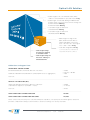
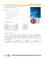
Optical LAN Solution
Simplifying Enterprise Passive Optical Networks (PON)
System Solution Guide EMEA
Optical LAN Solution
As optical fiber moves closer to end users, rapid changes are underway in both the data center and
the equipment closet. As a result, new installation and maintenance techniques are being employed
within enterprise applications. Passive Optical Network (PON) applications are now being deployed.
Fiber is no longer limited to just access equipment. Fiber connectivity to a single user is a reality.
TE Connectivity offers complete, end-to-end PON infrastructure solutions called Optical LAN
Solution (OLS). From the data center to the desktop, our customers have tapped the experience
and innovation of TE to build their PON networks. TE’s suite of end-to-end connectivity solutions
is truly comprehensive. This ordering guide highlights the most commonly used components that
feature field-proven attributes that can save time, money and help improve customer satisfaction.
The diagram below highlights an example of PON deployment using a TE
OLS solution. Each number corresponds to a specific innovative TE product
which is described in more details in this System Solution Guide.
Router
Fiber Panel
OLT
FDH - Fiber Distribution Hub
Fiber Wall Plate
ONT
FDT
Fiber Distribution Terminal
2
End-to-End Network Infrastructure
5 6
7
4
3
1
UCP Rack Mount
Fiber Panels
5
Fiber Patch Cord
2
Rapid Indoor Fiber Distribution
Hub (IFDH) 3000i with
"preconnectorized" stubs
3
Rapid Fiber Distribution
Terminal (FDT) with
"preconnectorized" stubs
4
RealFlexTM MDU Drop
Cables
1
6
Ethernet Cable
7
Wall Plate
Fiber Splitter Box (FSB)
Video WDM
Optional Component Configurations
2
www.te.com/enterprise-eu 01/14 109830EU
Optical LAN Solution
OLS By the Numbers
TE's Optical LAN Solution (OLS) is the end-to-end fiber optic infrastructure used for indoor
Passive Optical Networks (PONs), that takes a single strand of singlemode graded fiber
from the Data Center all the way to the individual desk or end device location.
This overview details some of the many features and benefits of Optical LAN
Solution, highlighting the impressive numbers behind the OLS story.
The Environmental Impact of CAT6 (voice),
Multimode fiber (backbone), and OLS (voice, data)
Traditional data/voice deployments require approximately 10m2 in the IDF based on 250 users. Workgroup switches, fiber
termination shelves, and patch panels require multiple racks that occupy valuable, and often expensive, floor space. The
Hub and Terminal Optical LAN Solution eliminates these racks of equipment thus freeing up floor space to be reallocated
for other value added, and in some cases revenue generating uses.
• Equipment is replaced by a single Fiber Distribution Hub (FDH) that
can be wall mounted for significant space savings
• A wall mounted 72, 288, or even 432-user FDH requires just 1m2 of space
• Aprox. 1m2 vs. 10m2 = On average more than 10x user density
www.te.com/enterprise-eu 01/14 109830EU
3
Optical LAN Solution
Power and Environmental Savings
OLS vs. Traditional LAN Architectures
• Once the equipment energy consumption is totaled, the following
formula can be used to calculate cost savings for commercial
power between traditional copper/fiber and OLS:
–– Equipment wattage x 1.1 x 2/1000 = KW
–– KW x 8760 hrs per year = KWH
–– 0.107€ (European Average cost per KWH) =
annual energy costs for the equipment
• Copper Solution example (700 users)
–– MDF has a router, servers, an analog gateway and a LAN switch
–– Each floor is equipped with multiple LAN switches and gateways
Combined AMPS =
229
Combined Watts = 82,368
Combined BTU = 52,948
• OLS Solution example (700 users)
–– MDF has the same level 3 WAN router, an Optical Line Terminal
(OLT), an edge router, and DC power distribution units
–– Each floor is equipped with low power consumption Optical Network
Terminals (ONTs) at each user and all other equipment is passive
Combined AMPS =
279
Combined Watts = 24,088
Combined BTU = 41,330
• The results – copper solution uses 50 AMPS less than OLS, however:
–– OLS saves 58,280 watts over copper solution (70%)
–– OLS saves 11,618 BTUs (22%)
Annual energy cost for copper solution: 77,205€
Annual energy cost for OLS solution: 22,578€
Projected Savings: 54,627€ year-over-year savings
4
www.te.com/enterprise-eu 01/14 109830EU
Optical LAN Solution
Operational Savings
OLS vs. Traditional LAN Architectures
• Reduced Troubleshooting and Maintenance Costs
–– Traditional copper/fiber networks require up to three sets of
electronics vs. OLS with only two, the OLT and ONT
• Reduced Maintenance Costs
–– OLS, being a fiber-only system, is inherently more reliable
due to the resistance to electromagnetic interference (EMI)
and radio frequency interference (RFI) and crosstalk
• Reduced Installation Costs
–– OLS offers plug-and-play installation, no splicing or field termination
–– Fiber offers greater tensile/pull strength (100200 lbf.) as compared to copper UTP (25 lbf.)
–– OLS incorporates bend insensitive singlemode
fiber for greater installation flexibility
• Reduced Life Cycle Costs – Optical LANs have a longer usable lifetime
because currently the bandwidth limitation of traditional singlemode fiber
is not known. Because of this, the network electronics can be upgraded
to the next generation to increase data without pulling new cable
Optical LAN Solution
Traditional Architecture
www.te.com/enterprise-eu 01/14 109830EU
5
Optical LAN Solution
Cable Plant Savings
Contrasting the Environmental Impact of CAT6 / CAT6A (horizontal), multimode fiber (vertical), and TE Optical LAN
Solution (OLS)
The environmental impact of choosing OLS over traditional structure cabling architectures can be significant. The
following scenario compares the environmental impact and cable costs reduction of traditional CAT6 / CAT6A and
multimode fiber versus OLS. The analysis is based on the same scenario found on page 4 using 700 users model.
4 Port ONT
Splitter
Riser Closet
Floor 1
Splitter
Fiber Distribution
Terminal
SM Fiber
*Occupies minimum space and does
not require power, cooling, battery backup
Riser Closet
Floor 2
OLT
*Requires - Power, Cooling, Battery Backup
UCP Patch Panel
Riser Closet
Floor 3
Workgroup
Switch*
Work Area
WAP
CAT 5e/6 Cabling
MM Fiber
Riser Closet
Floor 2
Workgroup
Switch*
Work Area
WAP
CAT 5e/6 Cabling
MM Fiber
Riser Closet
Floor 2
Workgroup
Switch*
Work Area
WAP
CAT 5e/6 Cabling
Core
Switch/
Router
6
www.te.com/enterprise-eu 01/14 109830EU
Optical LAN Solution
• Cable weight for 12 core multimode fiber (MMF)
cables for vertical backbone up to 60 meters: 18 kg
• Cable weight of horizontal cabling for 1400 CAT6 &
CAT6A outlets (2 ports per user) 55 metre average run:
CAT6A Shielded: 2800 kg
CAT6 Unshielded: 2660 kg
• Total cable weight for MMF and
Shielded CAT6A: 2818 kg
• Total cable weight for MMF and
Unshielded CAT6: 2678 kg
• Cable weight for single mode
(OS2) bend insensitive fibre to
support 350 ONTs (2 ports per
user) – 70 metre run* - Converged
voice – data – video: 221 kg
• Total cable weight OLS: 221 kg
• Total weight savings
for 700 users: 2597 kg
vs Shielded CAT6A
(*) 70 metres takes into consideration the
vertical and horizontal runs combined
• Total weight savings for
700 users: 2457 kg vs.
Unshielded CAT6
Cable Cost Saving per User:
TRADITIONAL COPPER & FIBRE
CAT6 Unshielded (UTP) horizontal cable run of 55 metre
= 23.10€
x 2 (ports) = 46.20€
Multimode Fibre OM4 vertical backbone (shared uplink access to aggregation)
= 1.93€
Total cost= 48.13€
OPTICAL LAN SOLUTION (OLS)
Single Mode OS2 Bend Insensitive cable run of 70 meter
(each fiber run supports a 4 port ONT - 2 users)
= 24.50€
/ 2 = 12.25€
Total cost= 12.25€
TOTAL CABLE COST SAVINGS PER USER
= 35.88€
TOTAL CABLE COST SAVINGS FOR 700 USERS
= 25,116€
Please contact TE Connectivity for a customised in depth comparison, our expert personnel will be glad to assist and
provide a comprehensive anaylys to demonstrate to actual cost savings on a case by case basis.
www.te.com/enterprise-eu 01/14 109830EU
7
Optical LAN Solution
Architectural Design Options
Just like traditional point-to-point networks, Passive Optical Networks (PON) can be varied depending upon network
needs, architecture, building layout, and economics. TE offers a designer the widest variety of cabling solutions available
for Passive Optical Networks. The following potential network designs are shown as guidelines for PON applications.
They may be used alone, or in combination when added to the appropriate PON electronics. TE always suggests that a
systems integrator be involved when designing a PON architecture to ensure the optimum performance of the network
electronics and the optical network.
FDH/FDT Rapid Reel Solution – Option 1
• Least amount of floor space
• Least amount of cable
• Greatest overall building savings
Mini RDT RapidReel
Wall Mount page 14
or
OLT
UCP Fiber Panel
page 10
MDF
72, 288, or 432
Fiber Hub page 11
MPO
RDT RapidReel
page 14
MPO
IDF
Zone
SCAPC
ONT
User Area
TFP Cassette/FSB32 – Option 2
• Zone splitting
• Moderate floor space
• Less cable than home run solution
RDT RapidReel
page 14
OLT
or
UCP Fiber Panel
page 10
MDF
8
UCP Fiber Panel
page 10
MPO
IDF
SCAPC
FSB-32 Indoor
Enclosure page 15
Zone
SCAPC
ONT
User Area
www.te.com/enterprise-eu 01/14 109830EU
Optical LAN Solution
Centralized Splitting – Option 3
• Low cable
usage
• Easy design
OLT
• Central Splitting
Splitter Adapter Plate
page 13
Mini RDT
page 14
Splitter adapter
in enclosure
page 13
MDF
MPO
Zone
ONT
SCAPC
User Area
ONTs can also be located in a
consolidation area in the IDF zone or by
means of an enclosure or in-ceiling tile as
shown in the images below.
Splitter Adapter Plate – Option 4
• Cost
competitive
Splitter adapter in
enclosure
page 13
or
OLT
UCP Fiber Panel
page 10
MDF
IDF or
Zone
• Simplistic
design
• Flexible
Splitter adapter in
wall mount box
page 13
SCAPC
• Traditional LAN
architecture
SCAPC
ONT
User Area
www.te.com/enterprise-eu 01/14 109830EU
9
MDF/IDF
Optical LAN Solution
UCP Patch Panel Angled and Flushmount
FEATURES
• 19” 1U unloaded modular patch panel with support for 4 Quick-Fit Modules
• Angled and flush style panels available
• Modular, rear cable management for both horizontal Copper and Fiber cables
• Accepts Pre-terminated Cu or FO cassettes or
Field-terminated Copper modules
• Including grounding bolt
Color: black (RAL 9005)
ORDERING INFORMATION
Description
Part Number
UCP Patch Panel 1U Angled
1-1671590-1
UCP Patch Panel 1U Flush
1-1671594-1
Xtra-U Subfloor Panel Holder Kit
FEATURES
• Suitable for Copper and Fiber installations
• Allows up to 630mm gap between support pillars
• Available for 1, 2 or 4U
• Bracket set to install 19” panels in the false floor area underneath cabinets/racks
• Attachable to support pillars with round or square cross-section (diameters from 14 to 30mm)
Color: galvanized
ORDERING INFORMATION
Description
Part Number
Xtra-U Subfloor Panel Holder Kit 1U
1671189-1
Xtra-U Subfloor Panel Holder Kit 2U
1671189-2
Xtra-U Subfloor Panel Holder Kit 4U
1671189-4
Xtra-U Aerial Panel Holder Kit for Wire Mesh Cable Trays
FEATURES
• Universal bracket for installing 19”patch
panels above cabinets /racks
• Can be attached to wire mesh cable trays
• 2U and 4U version available
Color: galvanized
ORDERING INFORMATION
Description
Part Number
Xtra-U Aerial Panel Holder Kit (2U) for Wire Mesh Trays
1-1671603-1
Xtra-U Aerial Panel Holder Kit (4U) for Wire Mesh Trays
1-1671603-2
10
www.te.com/enterprise-eu 01/14 109830EU
IDF
Optical LAN Solution
Rapid Fiber Distribution Hub (iFDH)
TE‘s Rapid Fiber Distribution Hub organizes and administers optical fiber cables
and passive optical splitters for enterprise PON applications. The enclosures
support plug-and-play termination with a cross-connect/interconnect interface
that makes installation, maintenance, and changes faster and easier. The
RapidReel feeder cable speeds up installation time and conveniently stores
slack inside the iFDH.
Rapid Indoor FDH
front panel
FEATURES
• Supports plug-and-play termination
• Can be either wall or rack mounted with the hardware provided
• Traditional swing-frame design allows superior rear access
• Includes RapidReel feeder cable
• Designed to meet NEMA-12 requirements
• UL 1863 Listed
Rapid Indoor FDH
with Easy Access to
Built-in MPO Panel
ORDERING INFORMATION
Description
Feeder Cable Type
Distribution Type
Feeder Stub Length
100’
72-Port with 9 splitter ports
72-Port Empty Hub
288-Port with 18 splitter ports
288-Port Empty Hub
432-Port with 22 splitter ports
432-Port Empty Hub
12-fiber plenum
6 MPO adapters
250’
OLH-MK072J00M0MKEA
OLH-MK072J00M0MKBA
100’
OLH-MM288J00M0MKCB
250’
OLH-MM288J00M0MKEB
500’
OLH-MM288J00M0MKBB
OLH-MK072J00M0M000
24 MPO adapters
No feeder cable**
24-fiber plenum
OLH-MK072J00M0MKCA
500’
No feeder cable**
24-fiber plenum
Part Number
OLH-MM288J00M0M000
36 MPO adapters
100’
OLH-MN432J00M0MKCB
250’
OLH-MN432J00M0MKEB
500’
OLH-MN432J00M0MKBB
No feeder cable**
OLH-MN432J00M0M000
*Note: Splitters are purchased separately; ordering information on the following page.
www.te.com/enterprise-eu 01/14 109830EU
11
IDF
Optical LAN Solution
Mini Plug-and-Play Splitter Modules
TE‘s Mini Plug-and-Play Splitter Modules support centralized splitting
architectures. The modules are available in a wide range of split ratios. The
rugged packaging is built for high performance, while the true plug-and-play
design reduces installation time.
FEATURES
• Bend-optimized fiber and ruggedized extreme temperature cabling
• Operating temperature range -55° to +85° C
Plug and Play splitter
• Wavelength range of 1260-1635 nm
• Easy to insert and remove without affecting adjacent splitters
• UL 1863 Listed
FMT Rack Mounted Splitter Panel
SPECIFICATIONS:
Splitter Type
Max Loss
Typical Loss
Uniformity
Return Loss
Directivity
PDL
1x16
13.5 dB
12.8 dB
1.0 dB
55 dB
60 dB
0.3 dB
Wavelength Range
1260-1635 nm
1x32
16.7 dB
16.0 dB
1.3 dB
55 dB
60 dB
0.3 dB
1260-1635 nm
ORDERING INFORMATION
Description
Part Number
Mini Plug-and-Play Splitter
Angled SC Pigtails, Used with iFDH,
FSB, Splitter Drawer, and Splitter Panels
1RU FMT Rack Mount Splitter
with Splitter
1 RU Rack Mount Splitter Drawer
Accommodates up to 4 mini Plug-and-Play
Splitters (purchased separately)
12
1 x 32 splitter
OLS-MPP13266
1 x 16 splitter
OLS-MPP11666
1 x 8 splitter
OLS-MPP10866
2 x 16 splitter
OLS-MPP1P66
2 x 32 WDM Splitter
OLS-MPP1E66
2 x 32 splitter
OLS-MPP12A66
1 x 32 splitter
OPS-FMTSP-AJJ01
2 x 32 splitter
OPS-FMTSP-GJJ01
1RU Rack Mount Splitter Drawer
OPS-MPPACCRMPNL
www.te.com/enterprise-eu 01/14 109830EU
MDF/IDF
Optical LAN Solution
Splitter Adapter Plate
The splitter adapter plate offers Passive Optical LAN
designers a cost-effective method to split optical signals
to multiple locations/users using traditional cabling
and enclosure footprints. Reduced bend radius fiber
technology enables technicians to route fiber in the
cabinet in less time, saving installation costs. The splitter
adapter plate supports centralized splitting architectures
and can be used in a wide range of TE cabinets,
enclosures, wall mount boxes, and floor mount boxes. The
rugged packaging is built for high performance while its
plug-and-play design helps reduce installation time.
KEY FEATURES & BENEFITS:
• Bend-optimized and rugged fiber
• Extreme temperature cabling (Operating temperature: -55°C to +85°C)
• Superior loss performance at 1310nm to 1490nm and 1550nm
• Meets requirements of GR-1209 and GR-1221
• Optional front side input connection
• Terminated with SC/APC connectors
• 54 inch cable length
SPECIFICATIONS:
Splitter Type
Max Loss
Typical Loss
Uniformity
Return Loss
Directivity
PDL
1x16
13.5 dB
12.8 dB
1.0 dB
55 dB
60 dB
0.3 dB
Wavelength Range
1260-1635 nm
1x32
16.7 dB
16.0 dB
1.3 dB
55 dB
60 dB
0.3 dB
1260-1635 nm
ORDERING INFORMATION
Description
Part Number
Splitter Adapter Plate
1 x 32 Splitter Adapter Plate with splitter
2111684-1
1 x 16 Splitter Adapter Plate with splitter
2111684-2
Front input kit (cable assembly and adapter)
2111699-1
96 Fiber output, 3 Fiber input, Rack Mount Enclosure
4RU Enclosure (1 pc)
559552-2
12 SC/APC Adapter Plate (9 pcs)
559596-3
Splitter Adapter Plate (3 pcs)
2111684-1
Optional SC/APC MPO Cassette
1918447-1
96 Fiber output, 3 Fiber input, Rack Mount Panels
1RU Rack Mount Panel (4 pcs)
12 SC/APC Adapter Plate (9 pcs)
1777125-1
559596-3
Splitter Adapter Plate(3 pcs)
2111684-1
Optional SC/APC MPO Cassette
1918447-1
32 Fiber Wall Mount Box
Double Sided, Single Door Wall Mount Box
1435128-1
12F SC/APC Adapter Plate (3 pcs)
559596-3
Splitter Adapter Plate (1 pc)
2111684-1
www.te.com/enterprise-eu 01/14 109830EU
13
IDF/Zone
Optical LAN Solution
Rapid Fiber Distribution Terminal
TE‘s Rapid Fiber Distribution Terminal (FDT) provides a compact, NEMA-12 rated
solution for connecting optical fiber cables within enterprise environments and
serves as a distribution/consolidation point. It eliminates the need for splice cases
and separate cable assemblies by integrating the RapidReel cable payout system.
Use of factory terminated and tested MPO connectors instead of splicing provide a
plug-and-play environment that reduces labor costs and speeds project completion.
The Rapid FDT provides a lockable consolidation point and localized patch field,
allowing for precise cable length customization in the field, while reducing overall
cable volume and simplifying routing from the FDH to the user area. The iFDT‘s
compact footprint enables it to be placed under raised floors, above ceilings, or
wall mounted.
Rapid FDT
FEATURES
• Built-in RapidReel technology allows for easy payoff of MPO stub
• Patented break-away spool flanges reduce slack storage size to within the
enclosures footprint
• Utilizes reduced bend radius fiber
Rapid FDT
using slider adapter packs
• UL 1863 listed
ORDERING INFORMATION
Description
Stub
100’
Rapid FDT 12-fiber
Loose tube cable
MPO
Rapid FDT 24-fiber
Loose tube cable
Mini-RDT 12-fiber : Lengths over
100 ft use external reel
Feeder Stub Length
MPO
Part Number
OLR-SJ12J00D1002A
200’
OLR-SJ12J00D2002A
300’
OLR-SJ12J00D3002A
100’
OLR-SJ24J00D1002A
200’
OLR-SJ24J00D2002A
300’
OLR-SJ24J00D3002A
500’
OLR-SJ24J00D5002A
100’
ODT-SM12J00D03090
200'
ODT-SM12J00D0619A
300'
ODT-SM12J00D0929A
400'
ODT-SM12J00D1229A
500'
ODT-SM12J00D1529A
Mini RDT
12 Fiber
*Note: Other cable lengths available. Contact your local TE sales engineer.
Mini RDT and Spool
14
www.te.com/enterprise-eu 01/14 109830EU
Mini RDT Open and Pulling Rapid
Zone
Optical LAN Solution
Fiber Splitter Boxes
TE’s Fiber Splitter Boxes (FSB) are mini Fiber Distribution Hubs that can be
used for plug-and-play (PNP) or fusion splice applications.
When used as a plug-and-play box, they are ideal for uses such as lower
count floors or buildings, extra capacity requirements beyond the standard
Fiber Distribution Hub (FDH), and when localized splitting or physical path
redundancy (using a 2x32 split) is desired.
FSB-32 Indoor Enclosure
The same box can also be used to extend services beyond the primary building
to other smaller buildings with limited users on the campus. In this type of
application, the FSB is typically spliced to the OSP fiber cable connecting the
buildings and would offer the optical splitting required to provide PON services
to the second building.
These wall boxes provide a small footprint for splitting, terminating, and
splicing. FSBs accept standard plug-and-play splitters and can be easily added
after the wall box has been installed. FSBs accommodate 1x8, 1x16, 1x32, 2x16
and 2x32 splitters. Wall mounting provides significant space savings and the
unique swing frame design allows for easy access to the back section of the
wall box.
FEATURES AND BENEFITS
• Dual hinge design creates separation between rear splitter section and
front patching access
• Splitters can be easily installed after wall box installation allowing for
separate purchase
• Provides up to 32 customer access ports per splitter
–– Dual hinge provides small footprint on the wall while
maintaining excellent hand access to connectors
• Accepts standard mini-PNP splitter modules (same as iFDH)
• UL 1863 Listed
ORDERING INFORMATION
Description
FSB-32 Indoor Enclosure;
with SC/APC adapters, 32-fiber distribution
Optical Splitter Module - Angled SC Pigtails
Part Number
No splitters, no splice trays
OSB-SBJ032000000
No splitters, with heat shrink splice trays
OSB-SBJ232000000
(1) 1x32 splitter installed, no splice trays
OSB-SBJ032A10000
(1) 1x32 splitter installed, with heat shrink splice trays
OSB-SBJ232A10000
2 x 32 splitter installed, no splice trays
OSB-SBJ032G10000
2 x 32 splitter installed, with heat shrink splice trays
OSB-SBJ232G10000
1x32 splitter
OLS-MPP13266
1x16 splitter
OLS-MPP11666
1x8 splitter
OLS-MPP10866
2x16 splitter
OLS-MPP1P66
2x32 splitter
OLS-MPP12A66
www.te.com/enterprise-eu 01/14 109830EU
15
Zone/User
Optical LAN Solution
Optical Fiber Cables
The TE reduced bend radius singlemode cable assemblies are used to connect
the user area to the Rapid FDT or when connecting the ONT to the wall plate
at the user end of the PON. With nearly 40 years of fiber cable manufacturing
experience,
TE offers a complete family of high performance cable and related products.
SC Angled Polish
SC Ultra Polish
TE‘s singlemode reduced bend radius cable assemblies have a bend radius of
7.5 mm and are backwards compatible with standard singlemode fiber. TE offers
ultra physical contact (UPC) or angled physical contact (APC) SC connector
styles. TE maintains tight tolerances regarding the geometry and concentricity
of the ferrule to maintain low insertion loss values. All cable assemblies undergo
stringent testing for both insertion loss and return loss at the factory before
shipment which ensures a high quality product is delivered.
SC Simplex Drop Cable
ORDERING INFORMATION
Description
Part Number
SC/APC-SC/APC Simplex Drop Cable G.657-A.2, yellow
Y-2160593-X
SC/APC-SC/UPC Simplex Drop Cable G.657-A.2, yellow
Y-2160594-X
Y- -X
Length
Y- -X
Length
Y- -X
Length
Y- -X
Length
Y- -X
Length
Y- -X
Length
0- -1
1m
0- -5
5m
2- -5
25 m
4- -5
45 m
6- -5
65 m
8- -5
85 m
0- -2
2m
1- -0
10 m
3- -0
30 m
5- -0
50 m
7- -0
70 m
0- -3
3m
1- -5
15 m
3- -5
35 m
5- -5
55 m
7- -5
75 m
0 -4
4m
2- -0
20 m
4- -0
40 m
6- -0
60 m
8- -0
80 m
Simplex
9- -0
90 m
9- -5
95 m
OS2 Singlemode Optical Fiber Interconnect Cable
• Outer jacket color: yellow
• All fiber is bend-insenstive ITU-T G657.A2
Fiber
Tight
Buffering (900µm)
Aramid Strength
Members
Outer Jacket
ORDERING INFORMATION
Cable Type/Jacket Diameter
Simplex (2.0 mm)
16
Fiber Count
Unit Count Units (Fibers/Unit)
1
1 (1)
LSZH
4-1702690-6
www.te.com/enterprise-eu 01/14 109830EU
Optical LAN Solution
External Rodent Resistant Loose Tube System Cable
with corrugated steel armour
FEATURES
• LLDPE (Linear Low Density Polyethylene)
• Metallic rodent resistant (corrugated steel)
• For use in ducts and in direct burial applications
• Longitudinal and lateral water resistance
• Central gel-filled loose tube construction
• Excellent crush and impact resistance
• Suitable for all termination techniques
• Fiber category: OS2
• Option: ULSZH sheath for internal and external applications
ORDERING INFORMATION
Description
Part Number
Y-
Reel size
Fiber count: 4
Y-599681-4
1-
1 Kilometer
Fiber count: 6
Y-599682-4
2-
2 Kilometer
Fiber count: 8
Y-599692-4
3-
3 Kilometer
Fiber count: 12
Y-599683-4
4-
4 Kilometer
Fiber count: 24
Y-599690-4
MECHANICAL PERFORMANCE
Fiber count
No. of
tubes/fillers
Overall Ø
(mm)
Weight
(kg/km)
Installation tension max.
during installation (N)
Crush resistance
(N)
Minimum bend radius
during installation (mm)
4, 6, 8, 12
1
10
104
1250
3000
200
24
1
10.5
120
1250
3000
200
TEMPERATURE RANGE
Cable type
Transport/Storage
Installation
Operation
Gel filled, loose tube
– 20 to + 70 °C
– 5 to + 50 °C
– 20 to + 70 °C
www.te.com/enterprise-eu 01/14 109830EU
17
Optical LAN Solution
Category 6A LSZH UTP and S/FTP Patch Cords
FEATURES
• Supports 10 Gigabit Ethernet to a full 100m
• Exceeds the requirements of IEEE 802.3an (10GBASE-T) and
ISO/IEC 11801:2002 amendment/channel requirements
• Superior cable flexibility from stranded cores
• Boot maintains correct bend radius to
ensure maximum performance
ORDERING INFORMATION
Description
Cable Color
Cable Type
Part Number
-XX
Augmented Category 6 LSZH Patch Cord
RJ45 plug to RJ45 plug, T568B
Blue
LSZH UTP
6645 2 827-XX
-04
1.0 m
Blue
LSZH S/FTP
6830 2 881-XX
-07
2.0 m
Length
Red
LSZH S/FTP
6830 2 882-XX
-10
3.0 m
Yellow
LSZH S/FTP
6830 2 883-XX
-15
5.0 m
7.5 m
Green
LSZH S/FTP
6830 2 884-XX
-25
Orange
LSZH S/FTP
6830 2 885-XX
-33
10 m
Grey
LSZH S/FTP
6830 2 887-XX
Y- -X
Length
0.5 m
Other colors and lengths are available upon request.
Category 6A S/FTP Patch Cord RJ-45 LSZH
FEATURES
• Category 7 S/FTP stranded cable
• LSZH sheath
• Color-matched snagless boots
ORDERING INFORMATION
Description
Part Number
Color: white
Y-1711815-X
1- -1
Color: blue
Y-1711816-X
0- -1
1.0 m
Color: gray
Y-1711817-X
0- -2
2.0 m
Color: yellow
Y-1711818-X
0- -3
3.0 m
Color: red
Y-1711819-X
0- -5
5.0 m
Y-1711820-X
1- -0
10.0 m
Color: green
Other colors and lengths are available upon request.
18
www.te.com/enterprise-eu 01/14 109830EU
Optical LAN Solution
Category 6 S/FTP Patch Cord RJ-45 LSZH
FEATURES
• Category 7 S/FTP stranded cable
• LSZH sheath
• Color-matched snagless boots
• Universal B-wiring
ORDERING INFORMATION
Description
Part Number
Color: white
Y-959385-X
Color: gray
Y-1711076-X
Color: green
Y-1711077-X
Color: yellow
Y-1711078-X
Color: blue
Y-1711079-X
Other colors and lengths are available upon request.
Category 6 U/UTP Patch Cord RJ-45 LSZH
FEATURES
• Category 6 according to ISO/IEC 11801 and EN-50173-1
• 4 Pair stranded U/UTP cable
• LSZH sheath
• Color-matched snagless boots
• Universal wiring
ORDERING INFORMATION
Y- -X
Length
Description
Part Number
1- -1
0.5 m
Color: white
Y-1711091-X
0- -1
1.0 m
Color: gray
Y-1711093-X
0- -2
2.0 m
Color: blue
Y-1711094-X
0- -3
3.0 m
Color: green
Y-1711095-X
0- -5
5.0 m
Color: red
Y-1711096-X
1- -0
10.0 m
Other colors and lengths are available upon request.
www.te.com/enterprise-eu 01/14 109830EU
19
Optical LAN Solution
MiniPods
FEATURES
• External mounting points
• Can be passed through standard floor grommets
• Incorporated dust protection on each port
• Pre-loaded with modular connectivity (including CL jacks)
• 3, 4 and 6 port versions available
ORDERING INFORMATION
Description
Part Number
MiniPod Cat. 6 CL UTP 3 port
6540 1 684-03
MiniPod Cat. 6 CL UTP 4port
6540 1 678-04
MiniPod Cat. 6 CL UTP 6 port
6540 1 678-06
AMP-TWIST 6AS Consolidation Point Transition Cable Assemblies
FEATURES
• Assembly to connect the work area outlet with the
consolidation or transition point
• Saves time and money on moves, adds and changes
• According to ISO/IEC 11801
• Category 7 F/FTP solid cable according to
IEC 61156-5 and EN 50288-4-1
• LSZH sheath
• Universal wiring Color: white
ORDERING INFORMATION
Description
Part Number
AMP-TWIST 6AS SL jack w/o dust cover to RJ-45 plug; Class EA,
Y-1711825-X
AMP-TWIST 6AS SL jack with dust cover to RJ-45 plug; Class EA
Y-1711851-X
Y- -X
Length
0- -5
5.0 m
1- -4
7.5 m
1- -0
10.0 m
1- -5
15.0 m
2- -0
20.0 m
3- -0
30.0 m
Y- -X
Length
0- -5
5.0 m
Unshielded Consolidation Point Transition Cable Assemblies
FEATURES
• Assembly to connect the work area outlet with the consolidation
or transition point (SL 110C Jack to modular plug)
• Meets ISO/IEC 11801 and EN 50173-1
• 4 pair solid U/UTP cable
• LSZH sheath
• Universal wiring
Color: white
ORDERING INFORMATION
Description
Cat. 6; Class E
20
1- -4
7.5 m
1- -0
10.0 m
Part Number
1- -5
15.0 m
Y-1711027-X
2- -0
20.0 m
www.te.com/enterprise-eu 01/14 109830EU
Optical LAN Solution
Wall Mount Enclosure for 6 Modules, Unloaded, with Side Door
FEATURES
• Accepts 6 Snap-In-Modules (Snap-In Modules)
• Optional lock available (559501-2)
• Optional grommets available
• Splice tray holder kit available
• Designed for intrabuilding or campus backbone applications
• Reversible cable strain relief bracket
• Recessed, easy-to-use door latches
• Dimensions (for exact dimensions consult customer drawing):
16.5" (40 cm) H x 14" (35.5 cm) D x 5" (13 cm) W
Color: black (RAL 9005)
ORDERING INFORMATION
Description
Part Number
With grommets, cable glands and splice tray holder
1278755-4
Splice tray holder kit
1374526-1
Grommets
559496-2
Lock
559501-2
Fiber Optic 1U Plastic Fiber Patch Panel
FEATURES
• 1U sliding panel for ease of access and standard
deployment into 19 inch racks
• Internal cable management protects splices
and pigtails and maintains bend radius
• A PC-ABS construction means that the tray is both
lightweight whilst retaining mechanical strength
• UL94V -0 flammability rating, allows usage within a building
ORDERING INFORMATION
Description
Color
Adaptor
Fiber type
Part Number
Fiber patch panel 12 port
grey
6 x SC Duplex
singlemode
7033 1 101-12
Fiber patch panel 24 port
grey
12 x SC Duplex
singlemode
7033 1 101-24
www.te.com/enterprise-eu 01/14 109830EU
21
Optical LAN Solution
Wall Mount Enclosure 2F/4F (Plastic)
FEATURES
• Pre-installed adapter
• Size: 125 x 150 x 65 mm (W x H x D)
• IP 53 rated
ORDERING INFORMATION
Description
Part Number
Wall Mount Enclosure 2F, 1 x SC Duplex, SM
1671116-2
Wall Mount Enclosure 6F/12F (Plastic)
FEATURES
• Pre-installed adapters
• Incl. management ring
• Size: 225 x 280 x 85 mm (W x H x D)
• IP 53 rated
ORDERING INFORMATION
Description
Part Number
Wall Mount Enclosure 6F, 1 x SC Duplex, SM
1671117-2
Wall Mount Enclosure 12F/24F (Plastic)
FEATURES
• Pre-installed adapters
• Incl. management ring
• Supplied without splicing tray
• Size: 220 x 325 x 110 mm (W x H x D)
• IP 53 rated
ORDERING INFORMATION
Description
Part Number
Wall Mount Enclosure 12F, 1 x SC Duplex, SM
1671118-2
Wall Mount Enclosure 24F, 1 x SC Duplex, SM
1-1671118-2
22
www.te.com/enterprise-eu 01/14 109830EU
Optical LAN Solution
Universal Fiber Optic wall outlets
FEATURES
• Unpopulated wall outlets for all
Fiber-to-the-Desk applications
(Inserts to be ordered separately)
Color: pure white (RAL 9010)
ORDERING INFORMATION
Description
Part Number
“45x45” Outlet 45 x 45 mm for SC-Duplex adaptor; Color: white (RAL 9010)
183931-1
DIN Outlet for SC Duplex Adaptor; Frame: No; Color: almond (RAL 1013)
966936-2
DIN Outlet for SC Duplex Adaptor; Frame: No; Color: white (RAL 9010)
2-966936-2
Fiber coupler duplex SC/APC with ceramic ferrule; Color: green
2-5502776-3
Blank adapter module; Color: white
1116412-3
Fiber Optic Wall Outlet
FEATURES
• Designed for modern small-form-factor deployments
and into legacy Gigabit Ethernet deployments.
• Integrated cable management allows diverse
routing for excess spool management and
maintenance of bend radius whilst the Fiber
optic cable is housed in the solution.
• The footprint suits standard (BS4660) electrical wall
back boxes for deployment in trunking and walls.
• Designed to allow the insertion of heat shrink
splice protection holders giving the flexibility to
choose between direct termination and splicing.
• Anchor points allow the Fiber optic cable to be tied-off
at the point of entry into the base which prevents the cable from slipping back into a wall recess during installation.
• Per port labelling provides easy identification of each subscriber network link.
ORDERING INFORMATION
Description
Part Number
1 x SC duplex outlet
7033106902
2 x SC duplex outlet
7033106904
www.te.com/enterprise-eu 01/14 109830EU
23
Optical LAN Solution
AMP LightCrimp Plus Connectors
FEATURES
• Easiest and quickest fiber termination (less than one minute)
• Factory polished for consistent high quality and finish (no paper required)
• No epoxy, curing or UV-light required
• Complies with the relevant TIA/EIA, IEC, CECC und EN/IS standards
• Durability: 500 cycles
TECHNICAL DATA
• Ferrule: Ceramic
INSTRUCTION SHEET LIGHTCRIMP PLUS
LightCrimp Plus SC; English; Part Number: 408-4471
• Attenuation typical (dB): 0.3
• Temperature range: -10°C to +60°C
LightCrimp Plus SC Connectors
FEATURES
• SC connector (simplex)
• Ceramic ferrule
• With pre-installed and pre-polished fiber
ORDERING INFORMATION
Description
Part Number
Simplex SC OS2 APC; (250 μm + 900 μm only); Body: green;
Boot: Blue; Packaging: 10
2064184-1
Simplex SC OS2 (250 μm + 900 μm + 3 mm jacketed cable);
Body: blue; Boot: blue; Packaging: 10
6693276-1
Clips to connect two SC simplex connectors to one
SC duplex connector (2 clips needed); green
6348522-2
Quick-Fit Fiber Modules
FEATURES
• Universal Modules with Quick-Fit footprint
• Fit in all TE CONNECTIVITY Patch Panels
with Quick-Fit footprint
• Not interchangeable with push pin fixation
Color: black (RAL 9005)
Note: MT-RJ panel jacks NOT include
ORDERING INFORMATION
Description
Color
6x SC/APC duplex; Fiber Type: OS2; Ferrule: Ceramic
Green
Blank module
24
Part Number
1671201-4
1479698-1
www.te.com/enterprise-eu 01/14 109830EU
Optical LAN Solution
Video-WDM (Wavelength Division Multiplexer)
When RF video is required for OLS applications, wave-length division multiplexers
(WDMs) support combining the analog or digital video with the voice and data
from the OLT. TE‘s WDM modules and rack mounted shelves offer a compact
solution for OLS deployments.
WDM Module
WDM FEATURES
• Integrated into traditional TE fiber management systems
• Qualified to GR-1209 and GR-1221
• Rugged package protects delicate splitters from
installer handling or in harsh environments
12-Position FMT Drawer
(FMT-GVM000000-A72P)
• Industry-leading low loss
• Terminated with GR-326 certified connectors
VIDEO-WDM APPLICATION
Video EDFA
OLT
Patch
Cord Front
Video
WDM
Plug-ins
FMT-G 2RU
Chassis
Rear
FDH with MT
Connector
TFP
Panel
with PnP
Cassettes
Front
Rear
TFP Panel with
SC/APC Adapter
Cassettes
12f. MT
Singlemode
Adapter Port
ORDERING INFORMATION
Description
Part Number
FMT MicroVAM Chassis
12-Position, accommodates up to 24 MicroVam
modules. 2RU, 19/23” mounting, 12” deep
OMT-GVM000000-A72P
Dual MicroVAM Video-WDM Module
1310/1490 voice/data with 1550 video
Dual circuit
All front Input/output ports
Input 1 (OLT) connectors SC/UPC
Input 2 (EDFA) connectors SC/APC
Output (common) connectors SC/APC
Fits in FMT MicroVAM chassis listed above
OPM-HVJNJ02
Horizontal Glide Cable Manager
3RU with integrated slack storage spools
ODCCMHIBS-3U
Plug-and-play 2x32 WDM Splitter
OLS-MPP1E66
www.te.com/enterprise-eu 01/14 109830EU
25
Optical LAN Solution
Dual MicroVAM Video-WDM with integrated 1x2 splitter
For certain video RF applications, an additional split before the video WDM may
be desired. The MicroVAM unit pictured below offers a compact solution for adding
additional splits of the video signals prior to being combined at the video WDM
device. The MicroVAM unit fits into a FMT MicroVAM chassis.
SC/APC
EDFA INPUT
COMMON
2
SC/APC
OUTPUT
SC/UPC
OLT 2 INPUT
COMMON
1
SC/APC
OUTPUT
OLT 1 INPUT
SC/UPC
BLANK
DUAL MICROVAM VIDEO-WDM WITH INTEGRATED 1X2 SPLITTER APPLICATION
Desktop
ONT
1x2
Splitter
Video EDFA
Rapid FDT with
MT Connector
Wall
Plate
Video
WDM
Video WDM
FMT-G 2RU
Chassis
Video
WDM
Front
Rapid Reel
Rear
Rapid FDH with
MT Connector
OLT
TFP Panel
with PnP
Cassettes
Front
TFP Panel with
SC/APC Adapter
Cassettes
1x32
Rear
MT Adapter
Rapid Reel
MT Adapter
ORDERING INFORMATION
Description
Part Number
Dual Micro-VAM Video-WDM
1310/1490 voice/data with 1550 video
Dual circuit
1550 EDFA input integrated with 1x2 splitter
All front Input/output ports
Input 1 (OLT) connectors SC/UPC
Input 2 (EDFA) connectors SC/APC
Common (output) connectors SC/APC
Fits in FMT MicroVAM chassis listed below
OPM-HVJNJH02-VZB
FMT MicroVAM Chassis
12-Position, accommodates up to 12 MicroVam modules
2 RU, 19" or 23" mounting, 12" deep
OMT-GVM000000-A72P
26
www.te.com/enterprise-eu 01/14 109830EU
Optical LAN Solution
The Blown Fibre system from TE Connectivity
The Blown Fibre system from TE Connectivity provides a simple solution to manage evolving network
demands without the need for high initial capital expenditure or extensive network planning. Blown Fibre
enables optical networks to adapt to changing business requirements.
The TE solution allows optical fibres to be deployed on demand from one point of a network to
another (internal or external) using compressed air to blow optical fibre into pre-installed tubes.
Building your network using the TE Blown Fibre system could realise the
following benefits:
SIMPLIFIED PLANNING
• Network is built according to today’s needs
• Fibre count can be increased as demand grows
COST EFFECTIVE
• Pay as you grow – install empty tubes and only pay for fibre as and
when required, spreading capital investment over time
• Reduced splicing – minimises branching and splicing of traditional
networks, which reduces engineering costs
• Deployment of fibres is related to actual requirement
• Elimination of unlit fibre and the associated up front investment
INCREASED FLEXIBILITY
• Future proof network build
• Networks are easily upgraded, branched or extended, giving maximum
flexibility and uninterrupted fibre blowing right to the destination
• Simplified emergency restoration
• Latest and emerging fibre technologies can be deployed
SPEED OF CUSTOMER CONNECTIONS
• Equivalent performance for first connections, significantly reduced
timescales and costs for subsequent connections
• Existing tube routes can be interrupted at any place, allowing rapid network upgrades
www.te.com/enterprise-eu 01/14 109830EU
27
Optical LAN Solution
Blown Fibre
SINGLEMODE – BLOWN FIBRE UNIT
Singlemode Blown Fibre Units meet the OS2 industry
standard as set out in ISO/IEC 11801:2002 and is
compliant to ITU-T RECOMMENDATION G.652 C/D.
Ideally suited for deployment in metro area, campus
and building backbone environments, singlemode blown
fibre allows for maximum network design flexibility.
Each blown fibre unit has an external
coating of glass microspheres which assist in
blowing fibres over large distances.
All Optical Fibre Units are specifically engineered for
Blown Fibre applications. The small diameter units
have surface modifications to facilitate installation
with the Blowing Head. The units are approved by
British Telecom to the Specification CW 1574.
The Blown Fibre unit comes in the following variants:
- 2 fibre singlemode
- 4 fibre singlemode
- 8 fibre singlemode
-12 fibre singlemode
28
www.te.com/enterprise-eu 01/14 109830EU
Optical LAN Solution
Blown Tube
BLOWN TUBE – INTERNAL
Small diameter low friction tubes
provide the dedicated pathway for the
optical fibre units are integral to the
TE blown fibre solution. Empty High
Density Polyethylene (HDPE) tubes
are available in a variety of sizes,
combinations, and protective systems.
The tubes have all been rigorously
tested and enable the blown fibre
units to be blown the optimum
distance within the tube network.
A comprehensive range of jointing
accessories is available for tube-totube connections, reducing, gas and
water blocking.
The indoor range of products is
available in reduced fire hazard/Low
Smoke Zero Halogen (LSZH) options.
BLOWN TUBE – EXTERNAL
The outdoor range of products is
available in standard sub-duct, heavy
duty, anti-rodent, or armoured versions.
The tubing products (for both internal
and external applications) are available
in 4, 7 and 12 way variants (other
counts on request), each containing
5mm OD, 3.5mm ID sub-units in an
outer sheath.
www.te.com/enterprise-eu 01/14 109830EU
29
Optical LAN Solution
Internal Plant
GAS SEAL UNIT
CUSTOMER LEAD-IN UNIT
The Blown Fibre Gas Seal Unit can
be used at all customer entry points.
A wall mounted unit, it is positioned
internally at the cable entry point.
Gas sealing connectors facilitate the
transition of the incoming external
blown fibre tubing to the internal
blown fibre tubing. These connectors
are used to seal both populated (with
blown fibre bundle) and unpopulated
blown tubing. The unit is used for
internally fed cable or with a Customer
Lead-In Unit for cables entering through
the fabric of the wall.
The Customer Lead In Unit enables
external Blown Tube to be passed
through the building fabric from an
outside wall and can be used to enter
any type of building whether office,
factory or residential. The Customer
Lead-In Unit comprises two separate
units mounted either side of the wall
and connected by a length of conduit.
This product can also be used to
manage the entry of conventional cable.
INTERNAL TUBE DISTRIBUTION
UNIT
The Internal Tube Distribution Unit
(Internal TDU) has been designed to
allow maximum flexibility within building
applications. The Internal TDU accepts
a range of Indoor tube assemblies up
to 19 tube capacity. The units allow
individual tube breakout, re-routing
or gas/water sealing. The tubes are
positively managed to prevent excessive
tube bending.
Installation Equipment
INSTALLATION EQUIPMENT
The installation process for the blown
fibre units requires the use of additional
equipment items in conjunction with
the blowing head and compressor.
This range of equipment includes the
Regulator, Pan Guide, Pan Support
Frame, Fibre Inversion Pan, Pan
Inversion Ring, and Blowing Beads. The
full range of equipment is available from
TE. It is necessary for an installer to
attend the Installation Training Course
(booked through TE Connectivity UK)
prior to using this equipment.
30
www.te.com/enterprise-eu 01/14 109830EU
ACCESSORIES
An integral part of the TE Blown Fibre
Solution is the tube connection and
tube sealing products. A wide range
of products is available which enable
tubes to be connected together,
sealed from water or gas ingress,
or reduced from one tube size to
another. This range of accessories is
fully compatible with the Blown Fibre
Units and Blown Fibre Tube supplied
by TE.
Optical LAN Solution
PON System Guide Conclusion
PON is a point-to-multipoint network architecture in which unpowered optical splitters enable
one strand of singlemode optical fiber to serve multiple users with data, video and voice services
through a variety of Internet protocol (IP)-enabled devices, such as computers, wireless access
points (WAPs) and voice over IP (VoIP) phones.
We have demonstrated how a PON fiber cable infrastructure can greatly help to reduce the amount
of physical cable and associated costs when compared against a traditional copper structure cabling
network. On a typical installation of 700 users it is possible to reduce the total weight of the cabling
portion by more than 2.5 tons and deliver a cost saving of more than 25K dollars. Savings become
even more significant when combined with the overall cost reduction of the active equipment and
the associated annual running costs (OPEX) which from our previous calculation sums up to more
than 54K Euro.
Finally, different system configurations based on innovative fiber design technology such as
RapidReel™ can accommodate various network needs, architectures, buildings layout and economics.
TE Connectivity offers the widest variety and highest quality of cabling solutions to deliver the most
cost effective and streamlined Passive Optical Networks.
For more information and an accurate bespoke evaluation of the savings that PON can deliver to
your IT network please contact a TE connectivity representative.
www.te.com/enterprise-eu 01/14 109830EU
31
TE ENTERPRISE NETWORKS REGIONAL SALES HEADQUARTERS:
North America
Greensboro, NC, USA
Ph:+1-800-553-0938
Fx:+1-717-986-7406
Latin America
Buenos Aires, Argentina
Ph:+54-11-4733-2200
Fx:+54-11-4733-2282
EMEA
Kessel-Lo, Belgium
Ph:+32-16-35-1321
Fx:+32-16-35-2188
SAARC
Bangalore, India
Ph:+91-80-4011-5000
Fx:+91-80-4011-5030
Asia
Hong Kong, China
Ph:+852-2735-1628
Fx:+852-2735-1625
Pacific
Sydney, Australia
Ph:+61-2-8748-9500
Fx:+61-2-9748-8487
TE ENTERPRISE NETWORKS IN EUROPE, MIDDLE EAST AND NORTH AFRICA:
Austria
Vienna
Ph:+43-1-90560-1204
Fx:+43-1-90560-1270
Denmark
Glostrup
Ph:+45-70-15-52-00
Fx:+45-43-44-14-14
Hungary
Budapest
Ph:+36-1-289-1007
Fx:+36-1-289-1010
Norway
Nesbru
Ph:+47-99-66-77-50
Fx:+47-66-77-88-98
Spain
Montcada (Barcelona)
Ph:+34-93-291-0330
Fx:+34-93-291-0608
UK
Tewkesbury, Glos
Ph: +44-1684-857966
Fx: +44-1684-857988
Belarus
Minsk
Ph: +375-17-237-47-94
Fx: +375-17-237-47-94
Egypt
Cairo
Ph:+20-2-2419-2334
Fx:+20-2-2417-7647
Italy
Collegno (Torino)
Ph:+39-011-4012-111
Fx:+39-011-4012-268
Poland
Warsaw
Ph:+48-22-4576-700
Fx:+48-22-4576-720
Sweden
Upplands Väsby
Ph:+46-8-5072-5000
Fx:+46-8-5072-5001
Ukraine
Kiev
Ph: +380-44-206-2265
Fx: +380-44-206-2264
Belgium
Kessel-Lo
Ph:+32-16-35-2326
Fx:+32-16-35-2353
Finland
Helsinki
Ph:+358-95-12-34-20
Fx:+358-95-12-34-250
Kazakhstan
Almaty
Ph:+7-327-244-5875
Fx:+7-327-244-5877
Portugal
Evora
Ph:+351-961-377-331
Fx:+351-211-454-506
Switzerland
Steinach
Ph:+41-71-447-0-447
Fx:+41-71-447-0-423
Bulgaria
Sofia
Ph:+359-2-971-2152
Fx:+359-2-971-2153
France
Cergy-Pontoise
Ph:+33-1-3420-2122
Fx:+33-1-3420-2268
Lithuania
Vilnius
Ph:+370-5-213-1402
Fx:+370-5-213-1403
Romania
Bucharest
Ph:+40-31-860-2113
Turkey
Istanbul
Ph:+90-212-339-92-00
Fx:+90-212-339-92-02
Czech Rep. & Slovakia
Brno
Ph:+420-541-162-112
Fx:+420-541-162-223
Germany
Darmstadt
Ph:+49-6151-607-1547
Fx:+49-6151-607-1219
Netherlands
Den Bosch
Ph:+31-73-6246-246
Fx:+31-73-6246-958
Russia
Moscow
Ph:+7-495-790-7902
Fx:+7-495-721-1894
U.A.E.
Dubai
Ph: +971-4-3466511
Fx: +971-4-3466513
CATALOG
Contact us:
Please contact us at one of the regional
offices shown above.
TE Enterprise Networks:
www.te.com/enterprise-eu
TE Connectivity:
www.te.com
AMP-TWIST, FLEX-MODE, RapidReel, RealFlex, TrueNet, TE Connectivity, TE connectivity (logo), Tyco Electronics, and TE (logo) are
trademarks of the TE Connectivity Ltd. family of companies and its licensors.
While TE Connectivity has made every reasonable effort to ensure the accuracy of the information in this document, TE Connectivity does
not guarantee that it is error-free, nor does TE Connectivity make any other representation, warranty or guarantee that the information is
accurate, correct, reliable or current. TE Connectivity reserves the right to make any adjustments to the information contained herein at
any time without notice. TE Connectivity expressly disclaims all implied warranties regarding the information contained herein, including,
but not limited to, any implied warranties of merchantability or fitness for a particular purpose. The dimensions in this document are
for reference purposes only and are subject to change without notice. Specifications are subject to change without notice. Consult
TE Connectivity for the latest dimensions and design specifications.
© 2014 TE Connectivity family of companies. All rights reserved.
109830EU 01/14 Revision