1
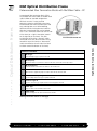
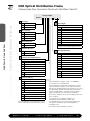
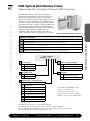
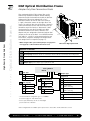
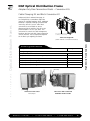
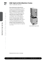
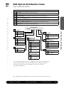
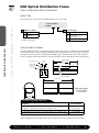
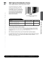
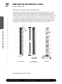
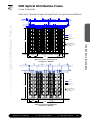
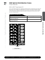
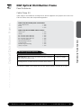
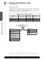
NGF Optical Distribution Frame
Introduction
Optical Distribution Frames
Fiber Termination Block (FTB)
ADC’s FTB is available with industry-standard adapters in block configurations of 72-, 96- and
144-positions. Also, a 192-position FTB is available using LC adapters. FTBs utilize sliding adapter
packs to gain easy access to both the front and rear terminations. To accommodate varying network
requirements and speed installation, FTBs can be ordered with adapters only or preterminated with
either intrafacility cable (IFC) or outside plant (OSP) cables.
Fiber Combination Block (FCB)
Our FCB provides termination and on-frame splicing capabilities. This configuration occupies two
mounting positions on the frame section. They are available with industry-standard adapters in
block configurations of 72-, 96- and 144-positions. An FCB with 192-positions is also available
using LC adapters.
Value-Added Module Block (VAM)
Adding signal management and enhancement functions, such as splitters, couplers and wavelength
division multiplexers, optimizes the value of your fiber network, by providing nonintrusive access to
the optical signal for monitoring and testing signal integrity. There is a block configuration available to
accommodate Micro Value-Added Modules (MicroVAMs) for applications requiring splitters or WDMs.
Fiber Optic Terminal Storage Panel
ADC’s fiber optic terminal storage panel is used as a storage apparatus for up to 16 feet of equipment
(FOT) jumpers at the fiber frame lineup. This panel can be installed between fiber frames and at the
end of a lineup.
•
103742AE
ADC’s next generation frame (NGF) product line has fiber frames
designed to fit a variety of network applications. Each frame option is
designed with an emphasis on superior cable management and ease
of use, including features such as ample trough space for cable and
jumpers, easy access to connectors and storage for jumpers. The frame
sections are shipped from the factory fully equipped with all cable
management hardware including integrated jumper slack storage.
4/11
High-Density Frame Solutions
Frame
www.te.com/adc
•
+1-952-938-8080
•
1-800-366-3891
4
NGF Optical Distribution Frame
Introduction
Recommended applications
Medium to large fiber count applications or any space constrained
applications. Highest fiber count solution available.
Description
High-density solution using 72-, 96-, 144- and 192-position
blocks (FTB)
Number of fibers,
future growth potential
Up to 29,177 in 17 frames using 144-position blocks,
SC connectors and 1.7 mm patch cords
Interconnect
Good
Cross-connect
Excellent
Accommodates on-frame splicing
Good
Accommodates off-frame splicing
Excellent
Density – terminations per frame
1,728 terminations using standard connectors;
2,304 terminations using LC connectors
Front access to rear connector
Yes
VAM capabilities
Yes. Separate panel required
Slack storage location
On-frame (integrated jumper slack storage)
Connector access
Sliding adapter pack
High-Density Frame Solutions
Up to 32,939 in 15 frames using 192-position blocks,
LC connectors and 1.7 mm patch cords
4/11
•
103742AE
Optical Distribution Frames
Product Overview
www.te.com/adc
•
+1-952-938-8080
•
1-800-366-3891
5
NGF Optical Distribution Frame
Things to Consider When Ordering
Optical Distribution Frames
103742AE
144 FTB
(1,728/frame)
96 FTB
(1,152/frame)
72 FTB
(864/frame)
NGF
12 frames
18 frames
24 frames
Front Facing NGF
4 frames
6 frames
8 frames
Calculation assumptions:
- Per Telecordia® GR-449-CORE, Issue 2 requirements
- 2.0 mm jumpers (maximum recommended diameter for all NGF products)
- 2" maximum jumper pile
- 50% of jumpers do not appear at any given place in lineup (50% rule)
Frame Lineup Capacity Comparisons
2.0 mm Jumpers/Maximum Recommended Diameter for NGF Products
NGF Frame:
1,728 Fiber Terminations
Conventional Frame:
1,152 Fiber Terminations
Conventional Frame:
648 Fiber Terminations
Horizontal trough space
30"
10" (5" Upper and Lower)
5" Lower
Maximum number of
terminations allowed in
a frame lineup before
exceeding 2" pileup
21,081
8,240
4,120
NGF Frame Considerations
Flexibility/ability to grow frame lineup
Interconnect
Cross-connect
On-frame splicing
Off-frame splicing
Rear access required
All front access
Footprint
Horizontal trough space available
NGF Frame
Front Facing NGF Frame
Slim Rack
Yes
Supports
Supports
Supports
Supports
Yes
No
30" Wide x
24" Deep
Yes
Supports
Supports
Supports
Supports
No
Yes
30" Wide x
19" Deep
No
Supports
Supports
Supports
Supports
No
Yes
19" Wide x
19" Deep
30"
9"
N/A
•
4/11
High-Density Frame Solutions
Frame Capacity Requirements (Important Facts on Trough Space)
Block and Frame Termination Capacity
NGF Block Termination Capacity
NGF Frame Termination Capacity
Min/Max Patch Cord Diameter
72
96
144
192 (LC connectors only)
864
1,152
1,728
2,304
2.0
2.0
2.0
1.7
www.te.com/adc
•
+1-952-938-8080
•
1-800-366-3891
6
NGF Optical Distribution Frame
Things to Consider When Ordering
Zoning Recommendations
IFC
1
Equipment
Jumper from
Equipment Optical
1
NOTE : Radius Limiters On FOTSB are
Removed at these Six Locations
to Allow IFC to Pass into FTB's.
1
Equipment Patch
Cord From FOT
Storage Bay
Fibers are Fanned Out and
Terminated to the Back
Side of the Adapters on
the Sliding Adapter Packs
Cable Clamp And Block
Conversion Kit Required
When Bringing Cable Into
Adapter Only Block
See Fiber Terminal
Block (FTB) Detail
KEY:
Routing is Down
The Inside Back
of the Fiber
Terminal Block
Fiber Optic
Terminal
Storage Bay
FTB -
Fiber
Terminal
Block
IFC -
Intrafacility
Fiber Cable
High-Density Frame Solutions
FOTSB -
FIBER TERMINAL
BLOCK DETAIL
FOTSB
NGF FRAME
Left
Vertical
FOTSB
NOTE : Equipment Jumpers Should be Populated from the
Bottom Block Position-Up and The OSP Blocks Should
be Deployed From The Top Block Position-Down.
Right
Vertical
Routing Multi-Fiber Cable & Fiber Patch Cords Together Into NGF Vertical
2.00"
FGS
IFC Cable
EQT Jumper
to FTB Rear
Cross-connect
Jumper
EQT Jumper
to FTB Front
84.00"
KEY
OSP - OSP Pre-term Block
MVAM - FRT & RR Access Microvam
FGS - Fiberguide System
NGF - Next Generation Frame
FTB - Fiber Term Block
FOTSB - F/O Terminal Storage Bay
EG - End Guard
MVAM - Microvam
4/11
•
103742AE
Optical Distribution Frames
IFC
NGF
5.00"
30.00"
19.00"
12.00"
Side View
(Shown W/EG Removed)
52.00"
Front View
EG
OSP
MVAM
FTB
FOTSB
EG
Front Facing NGF Application with Front and Rear Access MicroVAM Terminal Blocks
www.te.com/adc
•
+1-952-938-8080
•
1-800-366-3891
7
NGF Optical Distribution Frame
Things to Consider When Ordering
Zoning Recommendations
2.00"
Optical Distribution Frames
IFC Cable
Cross-connect
JUMPER
EQT Jumper
to FTB Front
84.00"
KEY
OSP - OSP Pre-term Block
SPLTR - Front Access Splitter Block
FGS - Fiberguide System
NGF - Next Generation Frame
FTB - Fiber Term Block
FOTSB - F/O Terminal Storage Bay
EG - End Guard
PON - Passive Optical Network
NGF
5.00"
30.00"
19.00"
40.00"
Side View
(Shown W/EG Removed)
Front View
EG
OSP
SPLTR
EG
Front Facing NGF PON Splitter Block Application
FGS
103742AE
Pre-Terminated Block
Adapter Only Block
IFC Cable
Equipment Jumper
Cross-connect Jumper
•
84.00"
KEY
EQT - Equipment Terminations
FOTSB - Fiber Optic Terminal Storage Bay
FGS - Fiberguide System
NGF - Next Generation Frame
OSP - Outside Plant Terminations
4/11
High-Density Frame Solutions
FGS
NGF FRAME 1
NGF FRAME 2
EQT
OSP
FOTSB
EQT
NGF FRAME 3
EQT
30.00"
EQT
FOTSB
OSP
12.00"
124.00"
NGF Cross-Connect Application with Equipment Jumper Storage
www.te.com/adc
•
+1-952-938-8080
•
1-800-366-3891
8
NGF Optical Distribution Frame
Things to Consider When Ordering
Main Components of the NGF
1) Select the desired Frame based on application
- Fiber Main Distributing Frame - Page 10
- Front Facing Fiber Main Distributing Frame - Page 11
- Fiber Slim Rack - Page 12
Catalog Number Quantity
___________________ ______
___________________ ______
___________________ ______
3) Fiber Optic Terminal Jumper Storage Panel - Pages 22-24
- 12" W (universal) - Page 24
- Front Facing 12" W (universal) - Page 24
- 8" W (left or right orientation) - Page 24
- Front Facing 8" W (left or right orientation) - Page 24
___________________ ______
___________________
___________________
___________________
___________________
___________________
___________________
______
______
______
______
______
______
___________________
___________________
___________________
___________________
______
______
______
______
___________________ ______
5) Modular Splitter Block - Page 21
___________________ ______
6) NGF to NG3 Frame Spacer Kit - Page 25
___________________ ______
7) End Guard
- End Guard (universal) - Page 26
- Front Facing End Guard (universal) - Page 26
___________________ ______
___________________ ______
8) Work Shelf - Page 26
___________________ ______
9) Frame Extender - Page 27
___________________ ______
10) Grounding Kit - Page 27
___________________ ______
11) AC Outlet Kit - Page 27
___________________ ______
12) Frame Installation Kit - Page 28
___________________ ______
13) Isolation Pad - Page 28
___________________ ______
14) Cable Clamp Kit - Page 29
___________________ ______
15) Sliding Adapter Pack - Page 30
___________________ ______
16) Patch Cord - Pages 103-107
___________________ ______
17) In-Line Attenuator - Page 108
___________________ ______
103742AE
4) MicroVAM Chassis - Page 21
•
Optional Equipment
*See page 31 for standard cross-connect patch cord lengths.
www.te.com/adc
•
+1-952-938-8080
•
1-800-366-3891
9
High-Density Frame Solutions
2) Select the desired Fiber Termination Blocks
- Preterminated Fiber Termination Blocks with
Multifiber Cable-IFC - Pages 13-14 - Preterminated Fiber Termination Blocks with
MPO Connectors - Page 15
- Adapter-Only Fiber Termination Blocks - Page 16
- Adapter-Only Fiber Termination Blocks-Conversion Kits - Page 17 - Fiber Combination Blocks - Pages 18-19
- Splice Tray - Page 20
- Splice Protector Sleeve - Page 20
4/11
Optical Distribution Frames
How to Order
NGF Optical Distribution Frame
Optical Distribution Frames
103742AE
•
The zone 4 rated fiber main distributing frame (FMDF) is the cornerstone of the NGF product line.
The footprint of the frame is GR-449-CORE, Issue 2 compliant. This innovative frame has six 5-inch
horizontal troughs for a total of 30 inches of horizontal trough space. This abundant trough space
minimizes fiber pile up and congestion leading to easier jumper traceability and removal. The frame
has 12 fiber termination block (FTB) mounting positions equally divided between vertical columns on
the left and right sides of the frame as shown in the figure below. The frame provides sufficient vertical
trough space for the highest termination density applications and includes built-in jumper
2.14 m storage that
(7') jumper length
will store up to 3.5 meters of jumper slack. The NGF is designed such that only a single
(6 meters) is required to go between any two termination points within a frame.
Left
Vertical
Jumper
Storage
Panel
Right
Vertical
Rear
Horizontal
Trough
(6)
2.14 m
(7')
FTB
Mounting
Position
(12)
2.14 m
(7')
762 mm (30")
483 mm
(19")
Front ISO View
Front View
483 mm
(19")
Ordering Information
762 mm (30")
Description
Dimensions (HxWxD)
NGF fiber main
distributing frame
Side View
483 mm
(19")
Maximum
Termination Capacity
2.14 m x 762 mm x 610 mm610 mm (24")
1,728
(7' x 30" x 24")
(2,304 using LC connectors)
483 mm
(19")
483 mm
(19")
610 mm (24")
762 mm (30")
Catalog Number
NGF-MDF7A100-30
483 mm
(19")
Each frame section includes heavy duty floor anchor bolts for concrete floor applications. See page 28 for additional
mounting options.
4/11
High-Density Frame Solutions
Fiber Main Distributing Frame
610 mm (24")
www.te.com/adc
•
+1-952-938-8080
•
1-800-366-3891
10
NGF Optical Distribution Frame
Front Facing Fiber Main Distributing Frame
Jumper
Storage
Panel
Left
Vertical
2.14 m
(7')
FTB
Mounting
Position
(12)
103742AE
2.14 m
(7')
Front
Horizontal
Trough
762 mm (30")
483 mm
(19")
762 mm (30")
Front ISO View
Ordering Information
Description
Dimensions (HxWxD)
Front View
483 mm
(19")
610 mm (24")
Maximum762 mm (30")
Termination Capacity
Catalog Number
2.14 m x 762 mm x 483 mm610 mm (24")
1,728
(7' x 30" x 19")
(2,304 using LC connectors)
NGF front facing
fiber main
distributing frame
483 mm
(19")
Side View
483 mm
(19")
NGF-F3MDF7A100-30
483 mm
(19")
483 mm
(19")
Each frame section includes heavy duty floor anchor bolts for concrete floor applications. See page 28 for additional
mounting options.
4/11
•
2.14 m
(7')
Right
Vertical
610 mm (24")
www.te.com/adc
•
+1-952-938-8080
•
1-800-366-3891
11
High-Density Frame Solutions
Optical Distribution Frames
The zone 4 rated front facing fiber main distributing frame (F3MDF) is designed for single-sided access
applications and may be mounted up against a wall or back-to-back to save floor space. Unlike the
FMDF, the more compact F3MDF is equipped with a single 9-inch horizontal trough on the front.
The F3MDF has 12 fiber termination block (FTB) mounting positions equally divided between vertical
columns on the left and right sides of the frame as shown below. The frame provides sufficient vertical
trough space for the highest termination density applications and includes built-in jumper storage that
will store up to 3.5 meters of jumper slack.
NGF Optical Distribution Frame
Fiber Slim Rack
The fiber slim rack is designed for lower density applications than the FMDF or F3MDF. It has six fiber
termination block (FTB) mounting positions and is designed for single-sided access applications. The slim
rack is intended for use in a single frame application and should not be used in a multi-frame lineup.
The built-in jumper storage panel will store up to 3.5 meters of jumper slack.
Optical Distribution Frames
FTB
Mounting
Position
2.14 m
(7')
2.14 m
(7')
Jumper
Storage
Panel
2.14 m
(7')
762 mm (30")
762 mm (30")
483 mm
(19")
Front ISO View
483 mm
483 mm
(19")(19")
Front View
(shown with covers open)
610 mm (24")
103742AE
Dimensions (HxWxD)
NGF fiber slim rack
2.14 m x 483 mm x 483 mm
(7' x 19" x 19")
Side View
610 mm (24")
Ordering Information
Description
483 mm
(19")
762 mm (30")
Maximum
Termination Capacity
Catalog Number
864
483 mm
(1,152 using LC connectors)
(19")
NGF-SLM7A100
483 mm
(19")
Each frame section includes heavy duty anchor bolts for concrete floor applications.
Not rated for zone 4 applications. See page 28 for additional mounting options.
•
610 mm (24")
4/11
High-Density Frame Solutions
When ordering FTBs for the slim rack, note that only LEFT oriented blocks are used on this frame.
www.te.com/adc
•
+1-952-938-8080
•
1-800-366-3891
12
NGF Optical Distribution Frame
Preterminated fiber termination blocks (FTBs)
are available with either indoor or outdoor rated
cable in ribbon or stranded configurations.
All blocks are 100% factory tested to
guarantee continuity and reliable connections.
Preterminated FTBs make installation quick and
easy, reducing labor costs. Before ordering,
determine the block orientation and cable exit
direction. Preterminated FTBs may be ordered
with a “left” orientation (mounts on the left side
of the frame) or a “right” orientation (mounts
on the right side of the frame). The cable
exit direction will be either “upward” (cables
terminated to the rear side of the block exit up
toward the top of the frame) or “downward”
(cables terminated to the rear side of the block
exit down toward the bottom of the frame).
High-Density Frame Solutions
Preterminated FTB with IFC
Definition of Variables
1
Block Type
General adapter type required in the FTB
2
Block Capacity
Maximum number of terminations that the FTB will accommodate when fully loaded
3
Block Orientation
Vertical column of the frame the FTB is to be mounted on
4
Cable Exit Direction
Direction the equipment jumpers or OSP cable will exit from the FTB
5
Connector and Adapter Type #1
Specific adapter/connector type required at the FTB
6
Connector Type #2
Specific connector type required at the far end opposite the FTB
7
Cable Type
Type of cable to be terminated to the FTB
8
Cable Length
Required length of the cable terminated to the FTB
Ordering information follows on next page.
4/11
•
103742AE
Optical Distribution Frames
Preterminated Fiber Termination Blocks with Multifiber Cable – IFC
www.te.com/adc
•
+1-952-938-8080
•
1-800-366-3891
13
NGF Optical Distribution Frame
Preterminated Fiber Termination Blocks with Multifiber Cable-IFC
Catalog Number
NGF-TB __ __ __ __ __ __ __ __ __ __ __
Optical Distribution Frames
103742AE
•
4/11
High-Density Frame Solutions
1 Block Type
1
2
4
8
SC
FC
LC
2 Block Capacity
B
C
M
Q
72
96
1441
192 (LC only)1, 3
3 Block Orientation
L
R
Left
Right
Cable Length
Standard Single-Ended
016 16 m (50')
023 23 m (75')
031 31 m (100')
046 46 m (150')
061 61 m (200')
077 77 m (250')
092 92 m (300')
122 122 m (400')
153 153 m (500')
Non-Standard
Use XXX for non-standard length in meters
4 Cable Exit Direction
U
Upward
D
Downward
7 Cable Type (IFC Riser)2
Singlemode
ZB
72-fiber stranded
KA 72-fiber ribbon4
ZC
96-fiber stranded
EG
96-fiber ribbon4
ZD
144-fiber stranded
FJ
144-fiber ribbon4
GT
192-fiber stranded (2 x 96)
EJ
192-fiber ribbon (2 x 96)4
Multimode (50/125 µm) LOMMF 300 m
WE 96-fiber stranded
WG 144-fiber stranded
TF
192-fiber stranded (2 x 96)
5 Connector and Adapter Type #1
Singlemode
7
SC ultra polish
L
SC angled polish
2
FC ultra polish
K
LC ultra polish (144 and 192 only)
M LC angled polish (144 and 192 only)
Multimode (50/125 µm) Aqua5
T
SC
C
LC (144 or 192 only)
6 Connector Type #2
Singlemode
0
No connector/stub end
7
SC ultra polish
L
SC angled polish
2
FC ultra polish
K
LC ultra polish
M LC angled polish
Multimode (50/125 µm) Aqua5
0
No connector/stub end
T
SC
C
LC
Other configurations are available upon request.
Please contact ADC Technical Assistance Center.
www.te.com/adc
•
92 and 144 blocks using block type 1 or 2 cannot be
1
used in legacy 26" wide NGF frames.
2
Panels using ADC’s standard cable offering have a shorter
lead time than panels using a specific cable manufacturer.
ADC provides GR-409 compliant cable that meets or exceeds
our high quality standards. Standard cable offering above
will use Corning SMF28-e, Sumitomo, Alcatel or similar
singlemode fiber based on current market availability.
3
Due to space limitations, do not use Tracerlight® patch cords
in the 192 block.
4
See Pages 97-98 to configure breakout kits for
configurations using stubbed IFC ribbon cable.
5
It is standard practice to use aqua colored adapters with
laser optimized multimode fiber for identification of
10 Gigabit circuits
See previous page for definition of variables.
1
+1-952-938-8080
•
1-800-366-3891
14
NGF Optical Distribution Frame
Fiber termination blocks (FTBs) with MPO connectors
provide MPO connectability on the rear of the block for
easy connection of MPO fiber cables. The termination
portion of the fiber block utilizes sliding adapter packs to
gain easy access to standard connectors and adapters on
the front of the block and provides a location for standard
patch cord connections. The block is internally cabled at the
factory for easy installation and occupies one position of
the frame. Before ordering, determine the block orientation
needed as the blocks may be ordered with a “left”
orientation (mounts on the left side of the frame) or a
“right” orientation (mounts on the right side of the frame).
Preterminated FTB with MPO Connectors
Definition of Variables
1
Block Capacity Maximum number of terminations that the FTB will accommodate when fully loaded
2
Block Orientation Vertical column of the frame the FTB is to be mounted on
3
Front Connector and Adapter Type Specific adapter/connector type required at the FTB
4
Pigtail Type Type of pigtail used within the FTB
5
Number of Pigtail Assemblies Number of pigtails to be pre-installed in the FTB
Catalog Number
NGF-MP __ __ 0 __ __ __
1 Block Capacity
C
96
M
Q
5 Number of Pigtail Assemblies
08
Used with 96-position block
144
12
Used with 144-position block
192 (LC only)1, 2
16
Used with 192-position block
1
4 Pigtail Type
L
Left
1
50/125 µm (OM3) LOMMF3
R
Right
5
Singlemode
3 Front Connector and Adapter Type
7
SC ultra polish
L
SC angled polish
•
Singlemode
2
FC ultra polish
4/11
103742AE
2 Block Orientation
K
LC ultra polish (144 or 192 only)
M
LC angled polish (144 or 192 only)
Multimode (50/125 µm) Aqua
T
SC
C LC (144 or 192 only)
1
92 and144 blocks cannot be used in
1
legacy 26" wide NGF frames.
2
ue to space limitations, do not use
D
Tracerlight® patch cords in the 192 block.
3
LOMMF – Laser optimized multimode fiber.
For multimode cable options, refer to literature# 103472AE.
For multimode cable options, refer to the TrueNet Solutions literature# 102094AE.
Other configurations are available upon request. Please contact ADC Technical Assistance Center.
For underfloor applications, an FOTSB (pg 24) must be used.
www.te.com/adc
•
+1-952-938-8080
•
1-800-366-3891
15
High-Density Frame Solutions
Optical Distribution Frames
Preterminated Fiber Termination Blocks with MPO Connectors
NGF Optical Distribution Frame
Optical Distribution Frames
Fiber termination blocks (FTBs) without fiber can be
ordered fully loaded with adapters. Before ordering,
determine the block orientation and cable exit direction.
Adapter-only FTBs may be ordered with a “left”
orientation (mounts on the left side of the frame) or
a “right” orientation (mounts on the right side of the
frame). The cable exit direction will be either “upward”*
(cables terminated to the rear side of the block exit up
toward the top of the frame) or “downward” (cables
terminated to the rear side of the block exit down
toward the bottom of the frame). All blocks with
adapters only are configured to terminate single or dual
jumpers on the rear of the block. If a multifiber breakout
style cable (i.e., OSP/IFC) is to be terminated to the rear
of the block, a separate clamping kit and replacement
rear storage area kit is required (see page 17).
299 mm
(11.75")
483 mm (19")
165 mm (6.5")
* When using the fiber optic terminal jumper storage panels
from page 24, a cable exit UP block must be used.
144-Position Right Upward FTB
Definition of Variables
1
Block Type General adapter type required in the FTB
2
Block Capacity Maximum number of terminations that the FTB will accommodate when fully loaded
3
Block Orientation Vertical column of the frame the FTB is to be mounted on
4
Cable Exit Direction Direction the equipment jumpers or OSP cable will exit from the FTB
5
Adapter Type Specific adapter type required in the FTB
Catalog Number
NGF-TB __ __ __ __ __
103742AE
1 Block Type
1
SC
2
FC
4
LC
5 Adapter Type
Singlemode
3 Block Orientation
B
72
C
96
•
2 Block Capacity
M
1441
4/11
High-Density Frame Solutions
Adapter-Only Fiber Termination Blocks
Q
192 (LC only)
L
Left
R
Right
7
SC ultra polish
L
SC angled polish
2
FC ultra polish
K
LC ultra polish
(144 or 192 only)
M
LC angled polish
(144 or 192 only)
4 Cable Exit Direction
1, 2
U
Upward
D
Downward
1
92 and 144 blocks using block type 1 or 2 cannot
1
be used in legacy 26" wide NGF frames.
2
ue to space limitations, do not use Tracerlight®
D
patch cords in the 192 block.
Multimode (50/125 µm) Aqua
T
SC
C
LC (144 or 192 only)
Other configurations are available upon request. Please contact ADC Technical Assistance Center.
www.te.com/adc
•
+1-952-938-8080
•
1-800-366-3891
16
NGF Optical Distribution Frame
Adapter-Only Fiber Termination Blocks – Conversion Kits
Adapter-only blocks ordered from page 16
are configured to accommodate single fiber
jumpers or multifiber breakout cables. Additional
hardware is required if loading a preterminated
intrafacility cable (IFC) or OSP cable. Block
conversion kits are available to convert
adapter-only blocks to blocks that will accept
preterminated IFC or OSP style cables. The
conversion kits contain the cable management
hardware, brackets and cable clamps required to
convert the block. The kit required will depend
on the block style originally purchased.
Rear Cable Mangement Tray
for 144 Block Conversion Kits
Ordering Information
Description
Catalog Number
Block type originally purchased
72-position blocks
NGF-ACCOSPKIT02
96-position blocks with rear cable management; (Ordered before June 2002)
NGF-ACCOSPKIT01
96-, 144-, or 192-position Left Up blocks
NGF-ACCRCMSLU
96-, 144-, or 192-position Right Up blocks
NGF-ACCRCMSRU
96-, 144-, or 192-position Left Down blocks
NGF-ACCRCMSLD
96-, 144-, or 192-position Right Down blocks
NGF-ACCRCMSRD
Cable Clamp
•
4/11
144-Position FTB Loaded
with Jumpers
www.te.com/adc
•
+1-952-938-8080
144-Position FTB Loaded with
Multifiber Breakout Cable
•
1-800-366-3891
17
High-Density Frame Solutions
144-Position Right FTB
(Shown with IFC Conversion Kit Loaded)
103742AE
Optical Distribution Frames
Cable Clamping Kit and Block Conversion Kit
NGF Optical Distribution Frame
Fiber Termination/Splice Block
•
103742AE
Optical Distribution Frames
Fiber combination blocks (FCB) provide the
option to splice IFC/OSP cables on the frame
with factory-installed fiber pigtails. The blocks are
available with several different adapter types in
block configurations of 72-, 96- or 144-positions.
Also, a 192-position FCB is available using LC
adapters. The termination portion of the fiber
combination block utilizes sliding adapter packs
to gain easy access to connectors on both the
front and rear side of the block. The block
is available with factory-installed pigtails for
easy installation. Splice trays are shipped with
the block if ordered with pigtails; otherwise
trays must be ordered separately. The block is
shipped with a cable clamp for OSP/IFC. The FCB
occupies two mounting positions on a frame
section. Before ordering, determine the block
orientation. FCBs may be ordered with a “left”
orientation (mounts on the left side of the frame)
or a “right” orientation (mounts on the right side
of the frame).
4/11
High-Density Frame Solutions
Fiber Combination Blocks
Ordering information follows on next page.
www.te.com/adc
•
+1-952-938-8080
•
1-800-366-3891
18
NGF Optical Distribution Frame
Fiber Combination Blocks
4/11
•
103742AE
Optical Distribution Frames
Definition of Variables
1
Block Type General adapter type required in the FCB
2
Block Capacity Maximum number of terminations that the FCB will accommodate when fully loaded
3
Block Orientation Vertical column of the frame the FCB is to be mounted on
4
Connector and Adapter Type Specific adapter/connector type required in the FCB
5
Pigtail Type Type of pigtail required
6
Number of Pigtail Assemblies Number of pigtails to be pre-installed in the FCB
7
Splice Chip Type of splice chip required for splice trays
Catalog Number
NGF-CB __ __ __ 2 __ __ __ __ __
1
SC
2
FC
4
LC
7 Splice Chip
2 Block Capacity
3
Mechanical (mass fusion)
6
Nortel QPAK (24-fiber
heat shrink fusion)
Connector and
4 Adapter Type
B
72
C
96
Singlemode
M
144 1, 2
7
SC ultra polish
06
72-position panel
Q
192 (LC only) 1, 2, 3
L
SC angled polish
08
96-position panel
2
FC ultra polish
12
144-position panel
K
LC ultra polish
(144 and 192 only)
16
192-position panel
M
LC angled polish
(144 and 192 only)
3 Block Orientation
L
Left
R
Right
Number of
6 Pigtail Assemblies
5 Pigtail Type
Multimode
(50/125 µm) Aqua
T
SC
C
LC
(144 or 192 only)
1
12-fiber stranded
5
12-fiber ribbon4
192 and 144 blocks using block style 1 or 2 cannot be used in legacy 26" wide NGF frames.
Must use Nortel QPAK splice chip in 144 and 192 blocks when splicing 24 single fibers.
3
Due to space limitations, do not use Tracerlight® patch cords in the 192 block.
4
Only available in singlemode.
1
2
Other configurations are available upon request. Please contact ADC Technical Assistance Center.
www.te.com/adc
•
+1-952-938-8080
•
1-800-366-3891
19
High-Density Frame Solutions
1 Block Type
NGF Optical Distribution Frame
Fiber Combination Block Accessories
Splice Tray
For use when splice trays are not included with block at time of order.
Catalog Number
Optical Distribution Frames
1 Number of Splices
1
2 Splice Tray Type
12 12 splices
FT
Bare fusion
24
HS
Heat shrink
(single fiber fusion)
MT
Mechanical (mass fusion)
24 splices
Available in 24-position
Splice Protector Sleeve
The splice protector sleeve is constructed to protect a splice post fusion. It is made from heat shrinkable
material and contains a built-in strength member for physical protection of the fusion splice. The splice
protection sleeve is placed on the fiber before making a splice, moved over the splice when the splice
fusion is complete and shrunk into place. They are available in either single fiber or mass fusion sleeves.
Heat Shrink Sleeve
60 mm ± 2 mm
(2.4" ± 0.08")
1.5 mm
(0.06")
56 mm ± 1 mm
2.2" ± 0.04"
Stainless Steel
Strength Member
Hot Melt
1.7 mm
(0.07")
3.8 mm (0.15")
Single Fusion Splice Protector Sleeve
FST-ACC001
•
103742AE
40 mm (0.16")
Mass Fusion Splice
Protector Sleeve
FST-ACC006
3.6 mm
(0.14")
maximum
4 mm
4/11
High-Density Frame Solutions
FST-DRS __ __ - __ __
O r d e(0.16")
ring Information
Description
Catalog Number
Splice protector sleeve for;
Single fiber – single fusion; 60 mm (2.4") length, 1 each
Single fiber – single fusion; 40 mm (1.6") length, 1 each
12-fiber ribbon – mass fusion – heat shrink; 40 mm (1.6") length, 1 each
FST-ACC001
FST-ACC005
FST-ACC006
Other configurations are available upon request. Please contact ADC Technical Assistance Center.
www.te.com/adc
•
+1-952-938-8080
•
1-800-366-3891
20
NGF Optical Distribution Frame
The new NGF MicroVAM chassis is designed
to mount on all standard NGF frames and is
interchangeable with termination, splice, and
storage modules. Each chassis accommodates up
to 12 MicroVAM modules. The NGF MicroVAM
chassis accommodates MicroVAM modules only.
For information on ADC legacy MiniVAM
chassis and modules, please contact ADC
Technical Assistance Center.
MicroVAM Chassis - Left Orientation
(Shown Loaded)
Description
Dimensions (HxWxD)
Catalog Number
NGF MicroVAM chassis, unloaded - left orientation;
accommodates 12 MicroVAM modules
300 mm x 455 mm x 132 mm
(11.8" x 17.9" x 5.2")
NGF-VSPM-7000L
NGF MicroVAM chassis, unloaded - right orientation;
accommodates 12 MicroVAM modules
300 mm x 455 mm x 132 mm
(11.8" x 17.9" x 5.2")
NGF-VSPM-7000R
Value-Added Module (VAM) System
ADC offers an expansive line of monitor, splitter, WDM and CWDM VAM plug-in modules designed
to meet all application needs. Please reference the Value-Added Module (VAM) System Catalog
#101663AE for details at www.adc.com or contact ADC Customer Service.
NGF Modular Splitter Block and Outside Plant Splitter System
For modular splitter block solutions for NGF frames and Outside Plant Splitter Solutions, please reference
OmniReach® FTTX Solutions – Passive Optical Splitter Modules Catalog #102902AE at www.adc.
com or contact ADC Customer Service.
•
4/11
www.te.com/adc
•
+1-952-938-8080
•
1-800-366-3891
21
High-Density Frame Solutions
Ordering Information
103742AE
Optical Distribution Frames
Value-Added Module (VAM) MicroVAM Chassis
NGF Optical Distribution Frame
Frame Accessories
Cover
Radius
Limiter
(14)
2.14 m
(7')
•
103742AE
Optical Distribution Frames
The fiber optic terminal jumper storage panel is an optional filler panel that provides up to 5 meters
(16.4 feet) of slack storage for jumpers that run between terminal equipment and the rear ports of
an NGF terminal block in cross-connect applications. This slack storage capability allows for greater
flexibility in determining jumper lengths and allows for use of more standard length jumpers. This panel
is installed within the NGF frame lineup between NGF frames. The fiber optic terminal storage panels
are available in two different configurations depending on the way the NGF frame system is zoned.
NGF frames can be zoned by vertical or by frame. A 12-inch wide panel is available that serves two
verticals (one on each side) for use when frames are zoned by vertical. Also, 8-inch wide versions are
available that serve a single vertical (left or right) for use when frames are zoned by frame.
610 mm (24")
305 mm (12")
Front ISO View
Front View
(NGF-ACCFOTSB Shown)
Side View
4/11
High-Density Frame Solutions
Fiber Optic Terminal Jumper Storage Panel
Ordering information follows on page 24.
www.te.com/adc
•
+1-952-938-8080
•
1-800-366-3891
22
NGF Optical Distribution Frame
Frame Accessories
FGS
IFC CABLE
EQT CABLE
CROSS-CONNECT
JUMPER
2.14M
(7')
KEY
OSP - Outside Plant Block Vertical
EQT - Equipment Block Vertical
FOTSB - Fiber Optic Terminal Storage Bay
FGS - Fiberguide System
NGF - Next Generation Frame
762mm
(30")
NGF FRAME 2
FOTSB
NGF FRAME 1
OSP
EQT
EQT
FOTSB
NGF FRAME 3
OSP
EQT
OSP
High-Density Frame Solutions
Optical Distribution Frames
Fiber Optic Terminal Jumper Storage Panel Zoning Recommendations
3.13M
(10.3')
305mm
(12")
NGF Cross-Connect Zoned by Vertical
1:1 Equation to OSP Ratio
IFC CABLE
EQT CABLE
CROSS-CONNECT
JUMPER
2.14M
(7')
KEY
OSP - Outside Plant Block Vertical
EQT - Equipment Block Vertical
FOTSB - Fiber Optic Terminal Storage Bay
FGS - Fiberguide System
NGF - Next Generation Frame
4/11
•
103742AE
FGS
NGF FRAME 1
OSP FRAME
762mm
(30")
FOTSB-SL
NGF FRAME 2
NGF FRAME 3
FOTSB-SR
EQT FRAME
2.95M
(116")
OSP FRAME
203mm
(8")
NGF Cross-Connect Zoned by Frame
2:1 Equation to OSP Ratio
www.te.com/adc
•
+1-952-938-8080
•
1-800-366-3891
23
NGF Optical Distribution Frame
Frame Accessories
Fiber Optic Terminal Jumper Storage Panel
Ordering Information
Description
Dimensions (HxWxD)
Catalog Number
2.14 m x 305 mm x 610 mm
(7' x 12" x 24")
NGF-ACCFOTSB
Front facing F3MDF 2.14 m x 305 mm x 483 mm
(7' x 12" x 19")
NGF-F3ACCFOTSB
FMDF left vertical 2.14 m x 203 mm x 610 mm
(7' x 8" x 24")
NGF-ACCFOTSB-SL
FMDF right vertical 2.14 m x 203 mm x 610 mm
(7' x 8" x 24")
NGF-ACCFOTSB-SR
Front facing F3MDF left vertical 2.14 m x 203 mm x 483 mm
(7' x 8" x 19")
NGF-F3ACCFOTSB-SL
Front facing F3MDF right vertical 2.14 m x 203 mm x 483 mm
(7' x 8" x 19")
NGF-F3ACCFOTSB-SR
Frame zoning: by frame, 203 mm (8")
•
103742AE
Optical Distribution Frames
FMDF 4/11
High-Density Frame Solutions
Frame zoning: by vertical, 305 mm (12")
www.te.com/adc
•
+1-952-938-8080
•
1-800-366-3891
24
NGF Optical Distribution Frame
Frame Accessories
NGF to NG3® Frame Spacer Kit
Ordering Information
Description
Catalog Number
NG3-NGFTRNTWN7A0R
Mounts on right side of NGF frame
and left side of NG3 frame
NG3-NGFTRNTWN7A0L
High-Density Frame Solutions
Mounts on left side of NGF frame
and right side of NG3 frame
•
103742AE
Optical Distribution Frames
The 2.5-inch wide frame spacer kit is required for transition between next generation frames (NGFs) and
NG3 frames. The kit includes six rear trough adapters that ensure the rear cable management features
of both fiber frames are utilized. Tie brackets and a kick plate are also included for a secure installation.
For technical documents outlining the proper procedure for making these transitions, please contact
your ADC sales representative.
4/11
NGF
NG3
64 mm
(2.5")
Spacer Kit Offset
Frame Spacer Kit
(NG3-NGFTRNTWN7A0L Shown)
www.te.com/adc
•
+1-952-938-8080
•
1-800-366-3891
25
NGF Optical Distribution Frame
Frame Accessories
End Guard
End guards provide protection for the fibers entering and exiting frames at the end of a lineup. They are
designed for universal fit to be used on either end of the lineup.
Dimensions (HxWxD)
Catalog Number
FMDF end guard
2.14 m x 127 mm x 610 mm
(7' x 5" x 24")
NGF-ACCEGD007
Front facing F3MDF end guard
2.14 m x 127 mm x 483 mm
(7' x 5" x 19")
NGF-F3ACCEGD007
Work Shelf
The work shelf can mount at any one of six positions
within the 30-inch NGF frame and anywhere along
the height of the frame. It provides a surface for
miscellaneous objects (i.e. isopropyl alcohol, tissues
and cotton swabs for cleaning connectors); also
provides a writing surface; or serves as an aid in field
terminating cables and jumpers.
Ordering Information
Description
Catalog Number
Work shelf; 762 mm (30")
NGF-ACCSHELF1-30
•
103742AE
Optical Distribution Frames
Description
4/11
High-Density Frame Solutions
Ordering Information
www.te.com/adc
•
+1-952-938-8080
•
1-800-366-3891
26
NGF Optical Distribution Frame
Frame Accessories
Frame Extender
Frame extenders are used to extend the height of a 7-foot frame to the appropriate ceiling height so
that it can be secured overhead.
Description
Catalog Number
762 mm (30") Wide Frames
Frame extender
305 mm (12")
610 mm (24")
1.4 m (54")
Slim Rack
NGF-ACCEXT12-30
NGF-ACCEXT24-30
NGF-ACCEXT54-30
NGF-ACCEXTSLM12
NGF-ACCEXT24-SR
NGF-ACCEXT54-SR
Grounding Kit
The fiber distribution frame is equipped with a grounding kit designed with mechanical fittings
including clamps, straps and connectors. Order this kit only if you are building a frame using your own
frame. When connecting frame ground to office ground conductor, an H-TAP bonding kit should also
be ordered.
Grounding kit includes:
2 hole terminal lug
#6 AWG copper tinned wire
Wire clips
#12-24 x 1/2" screws
1 each
13'
8 each
10 each
H-TAP bonding kit includes:
H-TAP
H-TAP insulated cover
2 hole terminal lug, crimp
Terminal lug, screw
#6 AWG stranded insulated wire
Star washer
No-ox grease
1 each
1 each
3 each
4 each
2'
6 each
1 tube
Ordering Information
*Included with all NGF frames
The AC outlet kit provides the hardware for mounting AC power outlets on the frame. Each kit
includes a prewired AC power outlet strip that mounts at the bottom of the frame.
4/11
103742AE
Catalog Number
•
Description
Grounding kit
H-TAP bonding kit
E-501-L37*
E-501-L166
AC Outlet Kit
Ordering Information
Description
Catalog Number
Dual outlet; mounts in base of NGF
AC outlet cover kit
www.te.com/adc
•
+1-952-938-8080
ACOK-2
RAC-0X0493
•
1-800-366-3891
27
High-Density Frame Solutions
Optical Distribution Frames
Ordering Information
NGF Optical Distribution Frame
Frame Accessories
Frame Installation Kit
Optical Distribution Frames
103742AE
•
4/11
High-Density Frame Solutions
Frame installation kits may be used on network frames and are seismic zone 4 rated.
Computer floor kit includes:
Threaded rods 4 each, 5/8" – 11" x 30"
Heavy nuts, locks and flat washers 12 each
Nuts with springs 4 each, 1/2" x 30" and shoulder washers
Unistrut and anchor kit
1 each, 10'
Overhead support kit includes:
Designation card holder
Two-bar channel
Framing clip with 0.56
Framing clip with 0.69
Clip J-bolt Threaded rod Hex nut Hex nut 1
4
4
4
4
2
4
4
each
each
each
each
each,
each,
each,
each,
1/2"
5/8"
1/2"
5/8"
– 13" x 18" long
x 18" long
x 13"
x 11"
Ordering Information
Description
Catalog Number
Frame installation kit for
Computer floor
Overhead support
FDF-ACC146
RINST-TOP7
Isolation Pad
A template for frame installation providing isolation between the frame and the ground.
Ordering Information
Description
Catalog Number
Isolation pad for
NGF FMDF and equipment frames
NGF front facing F3MDF and equipment frames
NGF slim racks
8" W NGF-F3ACCFOTSB-SL and NGF3ACCFOTSB-SR
8"W NGF-ACCFOTSB-SL and NGF-ACCFOTSB-SR
NGF-ACCFOTSB storage panels
NGF-F3ACCFOTSB storage panels
End guards for 610 mm (24") deep FMDF frames
End guards for 483 mm (19") deep F3MDF frames
www.te.com/adc
•
+1-952-938-8080
NGF-ACCISOP30X24
NGF-ACCISOP30X19
NGF-ACCISOP19X19
NGF-ACCISOP8X19
NGF-ACCISOP8X24
NGF-ACCISOPFS12X24
NGF-ACCISOPFS12X19
NGF-ACCISOPEG24
NGF-ACCISOPEG19
•
1-800-366-3891
28
NGF Optical Distribution Frame
Panel Accessories
Cable Clamp Kit
Cable clamp kits are available for securing IFC/OSP cable or equipment (FOT) jumpers on the rear of the
FTB. Each FTB has three cable clamp mounting positions.
Cable clamp bracket
O-ring
Screws
1 each
1 each
2 each
Cable clamp kit for IFC/OSP cables includes:
1
2
1
1
1
1
1
1
1
1
each
each
each
each
each
each
each
each
each
each
High-Density Frame Solutions
Clamp cover
Clamps
0.5" Grommet (inner diameter)
0.6" Grommet (inner diameter)
0.7" Grommet (inner diameter)
#14 - #6 AWG split bolt
Shield bonding connector
1-foot lead wire
#6 AWG ring terminal lug
Clamp cover plate
Ordering Information
Description
Catalog Number
Cable clamp kit for FOT patch cords (included with fiber termination
blocks loaded with adapters only)
NGF-ACCCLMP04
Cable clamp kit* for IFC/OSP cables, dielectric cable without
grounding hardware (included with fiber termination blocks with IFC)
NGF-ACCCLMP08
* One NGF-ACCCLMP08 is also included with each cable clamp kit and block conversion kit (see page 17).
4/11
•
103742AE
Optical Distribution Frames
Cable clamp kit for FOT patch cord includes:
www.te.com/adc
•
+1-952-938-8080
•
1-800-366-3891
29
NGF Optical Distribution Frame
Panel Accessories
Sliding Adapter Pack
Optical Distribution Frames
Block
Capacity
Adapter Pack
Configuration
Adapter Type
72-position
72-position
96-position
144-position (block code ‘M’)
192-position (block code ‘Q’)
SC
FC
SC, FC
SC, FC, LC
LC
2
6
4
6
8
pack
pack
pack
pack
pack
/ 4 pack
/ 4 pack
/ 6 pack
/ 8 pack
Adapter Pack
Type
A
E
J
K
J
Catalog Number
NGF-SAP __ 0 __ 00
Adapter Pack Type
Adapter Type
Singlemode
A
7
SC ultra polish
E
6 pack
4 pack / 4 pack1
6 pack / 6 pack
(all block code “M” blocks)
L
SC angled polish
J
2
FC ultra polish
K
K
LC ultra polish
(192 and 144 only)
M
LC angled polish
(192 and 144 only)
1
2 pack / 4 pack
8 pack / 8 pack with LC configuration.
Multimode (50/125 µm) Aqua
T
SC
C
LC
•
103742AE
Sliding Adapter Pack Configuration Guidelines
4/11
High-Density Frame Solutions
Sliding adapter packs house groups of fiber optic adapters and are mounted in fiber termination blocks
to provide easy access to connectors. Sliding adapter packs are available with SC, FC and LC adapters.
The adapters come in packs of two, four, six and eight depending on the adapter type and the desired
termination density. See table below for configuration guidelines.
Other configurations are available upon request. Please contact ADC Technical Assistance Center.
www.te.com/adc
•
+1-952-938-8080
•
1-800-366-3891
30
NGF Optical Distribution Frame
Frame Accessories
Standard Cross-Connect Patch Cord Lengths
Approximate
Patch Cord Length
Meters (Feet)
Same frame
Adjacent frames
3 to 4
5 to 6
7 to 8
9 to 10
6 m (18')
7 m (23')
8 m (26')
10 m (33')
11 m (36')
12 m (39')
Ordering Information for Patch Cords and Attenuators
ADC offers a comprehensive line of cable assembly and accessory products including patch cords, IFC
assemblies, attenuators, FasTerm® connectors and adapters to meet the demanding needs of today’s
network. Please refer to the Fiber Cable Assemblies Catalog #102880AE at www.adc.com for more
detailed information. For your convenience, ordering information for patch cords and attenuators can
also be found on pages 103-108
•
4/11
www.te.com/adc
•
+1-952-938-8080
•
1-800-366-3891
31
High-Density Frame Solutions
*Depending on office requirements, 11 or more frame sections may require the use of interbay tie panels.
For additional information, please call ADC Technical Assistance Center, 1-800-366-3891.
For recommended cross-connect method and installation instructions, refer to User Manual ADCP-90-285.
103742AE
Optical Distribution Frames
Total Number of
Sections Traversed*