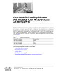
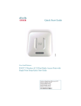
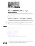
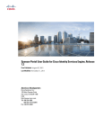
1
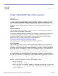
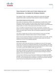
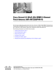
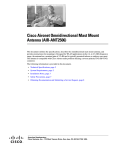
Cisco Aironet Four-Port Dual-Band
Polarization-Diverse Antenna
(AIR-ANT2513P4M-N)
October 2013
This document describes the AIR-ANT2513P4M-N antenna and provides electrical specifications and
mounting instructions. The antenna is a four-port polarization-diverse patch array that operates over the
2.4-GHz and 5-GHz Wi-Fi bands. It ships with an articulating mount for use on flat surfaces and masts
and is adjustable in both the horizontal and vertical planes. The radome is paintable using commonly
available non-conductive spray paints, such as Krylon or Rust-Oleum. The antenna is designed for use
in indoor and outdoor environments with Cisco Aironet 3702P Access Points.
The following information is provided in this document:
•
Technical Specifications, page 2,
•
System Requirements, page 7
•
Safety Instructions, page 7
•
Installation Notes, page 7
•
Choosing a Mounting Location, page 8
•
Installing the Antenna, page 8
•
Painting the Antenna, page 14
•
Obtaining Documentation and Submitting a Service Request, page 14
Cisco Systems, Inc.
www.cisco.com
Technical Specifications
Technical Specifications
Antenna Type
Dual-Band Polarization Diverse Patch Array
Operating Frequency Ranges
2.4-2.5 GHz
5.15-5.925 GHz
Nominal Input Impedance
50 Ohms
50 Ohms
VSWR
1.6:1
1.5:1 (above 5.7 GHz to 5.9 GHz)
2:1 (from 5.15 GHz to 5.7 GHz)
Peak Gain
13 dBi
13 dBi
Polarization (Ports A & C)
Vertical
Vertical
Polarization (Ports B & D)
Horizontal
Horizontal
Nominal Elevation Plane 3-dBBeamwidth 30 Degrees
30 Degrees
Nominal Azimuth Plane 3-dB Beamwidth 30 Degrees
30 Degrees
V-Pol Maximum Sidelobe Level
-15 dBc
-12 dBc
H-Pol Maximum Sidelobe Level
-10 dBc
-12 dBc
Front-to-Back Ratio
> 30 dB
> 30 dB
Connector Type
N-Female Bulkhead
Length
14.5 in. (36.8 cm)
Width
20 in. (50.7 cm)
Height
0.8 in. (2.11 cm)
Weight
81.1 oz. (2.3 kg)
Water/Foreign Body Ingress
IP-67
Operational Wind
100 MPH
Operating Temperature Range
-30° C to 70° C
Storage Temperature Range
-40° C to 85° C
Figure 1
ANT2513P4M-N front high view
Cisco Aironet Four-Port Dual-Band Polarization-Diverse Antenna (AIR-ANT2513P4M-N)
2
78-21447-01
Technical Specifications
2.4 GHz Antenna Radiation Patterns
2.4 GHz Ports A&C Azimuth Plane
2.4 GHz Ports A&C Elevation Plane
2.4 GHz Ports B&D Azimuth Plane
2.4 GHz Ports B&D Elevation Plane
Cisco Aironet Four-Port Dual-Band Polarization-Diverse Antenna (AIR-ANT2513P4M-N)
78-21447-01
3
Technical Specifications
5 GHz Antenna Radiation Patterns
5 GHz Ports A&C Azimuth Plane
5 GHz Ports A&C Elevation Plane
5 GHz Ports B&D Azimuth Plane
5 GHz Ports B&D Elevation Plane
Cisco Aironet Four-Port Dual-Band Polarization-Diverse Antenna (AIR-ANT2513P4M-N)
4
78-21447-01
Technical Specifications
Antenna and Bracket Dimensions
Figure 2 and Figure 3 show the overal dimensions of the antenna and bracket.
Figure 2
Antenna and Bracket Dimensions (in millimeters)
Cisco Aironet Four-Port Dual-Band Polarization-Diverse Antenna (AIR-ANT2513P4M-N)
78-21447-01
5
Technical Specifications
Figure 3
Rear View of Antenna (dimensions in millimeters)
Cisco Aironet Four-Port Dual-Band Polarization-Diverse Antenna (AIR-ANT2513P4M-N)
6
78-21447-01
System Requirements
System Requirements
This antenna is designed for use with Cisco Aironet 3702P Access Points. The antenna can be mounted
on a wall, a ceiling, or a pole with a maximum diameter of 5 inches (12.7 cm).
Safety Instructions
Warning
IMPORTANT SAFETY INSTRUCTIONS
This warning symbol means danger. You are in a situation that could cause bodily injury. Before you
work on any equipment, be aware of the hazards involved with electrical circuitry and be familiar
with standard practices for preventing accidents. Use the statement number provided at the end of
each warning to locate its translation in the translated safety warnings that accompanied this device.
Statement 1071
SAVE THESE INSTRUCTIONS
Warning
Only trained and qualified personnel should be allowed to install, replace, or service this equipment.
Statement 1030
Follow these safety instructions when installing your antenna.
•
Plan your installation procedure carefully and completely before you begin.
•
If you are installing an antenna for the first time, for your own safety as well as others, seek
professional assistance. Consult your dealer, who can explain which mounting method to use for the
location where you intend to install the antenna.
•
Select your installation site with safety, as well as performance, in mind. Remember that electric
power cables and telephone lines look alike. For your safety, assume that any line is an electric
power line until determined otherwise.
•
Call your local power company or building maintenance organization if you are unsure about cables
close to your mounting location.
•
When installing your antenna, do not use a metal ladder. Do dress properly: shoes with rubber soles
and heels, rubber gloves, and a long sleeved shirt or jacket.
•
If an accident or emergency occurs with the power lines, call for qualified emergency help
immediately.
Installation Notes
Because antennas transmit and receive radio signals, they are susceptible to RF obstructions and
common sources of interference that can reduce throughput and range of the device to which they are
connected. Follow these guidelines to ensure the best possible performance:
•
Mount the antenna to utilize its propagation characteristics. This antenna is designed to radiate
energy in a somewhat narrow beam from the front of the antenna. It should be aimed into the
intended coverage area.
Cisco Aironet Four-Port Dual-Band Polarization-Diverse Antenna (AIR-ANT2513P4M-N)
78-21447-01
7
Choosing a Mounting Location
•
Keep the antenna away from metal obstructions such as heating and air-conditioning ducts, large
ceiling trusses, building superstructures, and major power cabling runs. If necessary, use a rigid
conduit to lower the antenna away from these obstructions.
•
The density of the materials used in a building’s construction determines the number of walls the
signal must pass through and still maintain adequate coverage. Consider the following before
choosing the location to install your antenna:
– Signals penetrate paper, vinyl and drywall the easiest. A signal can penetrate five or six walls
constructed of drywall or wood.
– Signals are more heavily attenuated passing through concrete and solid-wood walls.
– Signals often reflect off thick metal walls and may not penetrate at all.
•
Install the antenna away from microwave ovens and 2-GHz cordless phones. These products can
cause signal interference because they operate in the same frequency range as the device to which
your antenna is connected.
Choosing a Mounting Location
The antenna should be mounted clear of any obstructions to the side or front of the enclosure. Keep in
mind that this antenna should be aimed into the intended coverage area, so you should mount the antenna
so that the desired mechanical tilt can be achieved. If possible, mount the antenna near the access point
so you can use the shortest possible connecting cables.
Installing the Antenna
You can install the antenna on any flat surface or on a pole with a minimum diameter of 2 inches
(5.08 cm) and a maximum diameter of 5 inches (12.7 cm). The antenna and one mounting flange are
connected together when shipped. When mounting the antenna you need to assemble the bracket
hardware, connect the antenna and bracket to the mounting surface, and adjust the antenna orientation.
Cisco Aironet Four-Port Dual-Band Polarization-Diverse Antenna (AIR-ANT2513P4M-N)
8
78-21447-01
Installing the Antenna
Contents of Antenna Bracket Kit
Figure 4 shows the parts included with the antenna bracket.
Figure 4
Antenna Bracket Kit Contents
1
Mounting flange
5
Flat washers
2
Mounting arm
6
Lock washers
3
Arm attachment bolts (5/16-18 x 1-5/8")
7
Arm attachment nuts (5/16-18)
4
Serrated washers
8
Hose clamps (50 – 135 mm adjustment)
Note
One flange (not pictured here) ships attached to the antenna. The flange pictured here is the one
that you attach to the wall or the pole.
Cisco Aironet Four-Port Dual-Band Polarization-Diverse Antenna (AIR-ANT2513P4M-N)
78-21447-01
9
Installing the Antenna
Tools and Equipment Required
You will need these tools to loosen and tighten the adjustment bolts on the bracket:
•
A 1/2 in. (13-mm) wrench or socket
To mount the antenna on a wall or ceiling, you will need these supplies:
•
Note
Four mounting screws or bolts and wall anchors
The fasteners and mounting surface should be capable of maintaining a minimum pullout force
of 150 pounds (68 kg) to support the weight of the antenna and bracket plus the potential wind
loading on the antenna.
To mount the antenna on a pole or mast, you will need either or both of these supplies:
•
Slotted screwdriver to tighten the screws on the hose clamps
•
A 5/16 in. (8mm) socket or box wrench
Note
The pole or mast must be rigid enough to hold the weight of the antenna plus the associated
forces produced by wind loads. In addition, the pole or mast must be structurally strong enough
to withstand the clamping force of the hose clamps.
You may need the following tools and equipment, which are not provided:
•
A drill and drill bit
•
A pencil
Mounting on a Wall or Ceiling
Follow these steps to mount your antenna on a wall or ceiling.
Step 1
Remove the antenna and bracket hardware from the shipping container.
Step 2
Determine the mounting location for the antenna.
Note
Step 3
The fasteners and mounting surface should be capable of maintaining a minimum pullout force
of 150 pounds (68 kg) to support the weight of the antenna plus the potential wind loading on
the antenna.
Attach the mounting bracket to the wall or ceiling using four screws or bolts and anchors through the
holes on the bracket. Figure 5 shows the wall-mount bracket.
Cisco Aironet Four-Port Dual-Band Polarization-Diverse Antenna (AIR-ANT2513P4M-N)
10
78-21447-01
Installing the Antenna
Figure 5
Wall-Mount Bracket and Dimensions (in millimeters)
4 slotted holes
for hose clamps
Step 4
Assemble the bracket hardware as shown in Figure 6.
Cisco Aironet Four-Port Dual-Band Polarization-Diverse Antenna (AIR-ANT2513P4M-N)
78-21447-01
11
Installing the Antenna
Figure 6
Assembling the Bracket Hardware
Step 5
Make sure you orient the antenna correctly (note the arrow on the back of the antenna that indicates the
top of the antenna). Use a 1/2 in. (13-mm) wrench to loosen the elevation adjustment bolt and the
elevation pivot bolt.
Step 6
Adjust the azimuth (side-to-side position) and elevation (up-and-down position) of the antenna. Loosen
the adjustment bolts slightly to allow for adjustment. Azimuth angle can be adjusted ±25 degrees and
elevation can be adjusted ±60 degrees. You can use the azimuth and elevation markings on the mounting
arm and the wall flange as a guide.
Step 7
After you adjust the antenna position, tighten the adjustment bolts and the pivot bolts. Tighten all bolts
to 18.7 +/- 5 lb-ft (25.4 Nm).
Step 8
Connect the antenna cables to the access point. The antenna ports are labeled A through D, from left to
right. Connect the antenna port A to connector A on the access point, antenna port B to connector B, and
so on. See the Suggested Cable section for cable recommendations.
Cisco Aironet Four-Port Dual-Band Polarization-Diverse Antenna (AIR-ANT2513P4M-N)
12
78-21447-01
Installing the Antenna
Mounting on a Pole or Mast
The antenna can be mounted on a pole or mast using two hose clamps.
Note
The pole or mast must be rigid enough to hold the weight of the antenna plus the associated
forces produced by wind loads. In addition, the mast must be structurally strong enough to
withstand the clamping force of the hose clamps.
To mount the antenna on a pole or mast, follow these steps.
Step 1
Follow steps 1 and 2 from the Mounting on a Wall or Ceiling section.
Step 2
Position and mount the mounting flange (Figure 4) onto the pole or mast using the hose clamps provided
in the kit. The hose clamps should pass through the slots on the mounting flange (Figure 5).
Step 3
Tighten the clamps only enough to hold the flange and antenna in place until the antenna is positioned
to its final position.
Step 4
Assemble the antenna and bracket to the flange as shown in Figure 6.
Step 5
Position the antenna, mounting bracket, and hose clamps on the mast.
Step 6
Tighten the hose clamps until the antenna is fully secure on the mast. Ensure that the antenna cannot
rotate about the mast.
Step 7
After the antenna is secured on the mast, adjust the azimuth and elevation.
To adjust the azimuth and elevation, use a 1/2 in. (13-mm) wrench to loosen the adjustment bolts.
Azimuth can be adjusted ±25 degrees and elevation can be adjusted ±60 degrees.
Step 8
After you adjust the antenna position, tighten the adjustment bolts. Tighten all bolts to 18.7 +/- 5 lb-ft
(25.4 Nm).
Step 9
Connect the antenna cables to the access point. The antenna ports are labeled A through D, from left to
right. Connect the antenna port A to connector A on the access point, antenna port B to connector B on
the access point, and so on. See the Suggested Cable section for cable recommendations.
Suggested Cable
Cisco recommends a high-quality, low-loss cable for use with the antenna, such as Cisco
AIR-CAB005LL-R-N= (5-ft low-loss cable with RP-TNC and N-type connectors). Four cables are
required.
Note
Coaxial cable loses efficiency as the frequency increases, resulting in signal loss. The cable should be
kept as short as possible because cable length also determines the amount of signal loss (the longer the
run, the greater the loss).
Cisco Aironet Four-Port Dual-Band Polarization-Diverse Antenna (AIR-ANT2513P4M-N)
78-21447-01
13
Painting the Antenna
Painting the Antenna
Painting the antenna and the bracket does not affect its performance if you use standard exterior-grade,
oil-based or latex paint. Do not use metallic or metallic-flake paints, which will degrade antenna
performance.
Note
Before painting the antenna, cover the pressure-release vent on the rear, lower-left of the antenna with
masking tape to prevent clogging (Figure 3).
Cisco recommends Krylon Fusion for Plastic or Rust-Oleum for Plastic (which might require a primer
coat). For best results, follow the surface preparation suggestions from the paint manufacturer.
Obtaining Documentation and Submitting a Service Request
For information on obtaining documentation, submitting a service request, and gathering additional
information, see the monthly What’s New in Cisco Product Documentation, which also lists all new and
revised Cisco technical documentation, at:
http://www.cisco.com/en/US/docs/general/whatsnew/whatsnew.html
Subscribe to the What’s New in Cisco Product Documentation as a Really Simple Syndication (RSS) feed
and set content to be delivered directly to your desktop using a reader application. The RSS feeds are a free
service and Cisco currently supports RSS Version 2.0.
Cisco and the Cisco logo are trademarks or registered trademarks of Cisco and/or its affiliates in the U.S. and other countries. To view a list of
Cisco trademarks, go to this URL: www.cisco.com/go/trademarks. Third-party trademarks mentioned are the property of their respective owners. The
use of the word partner does not imply a partnership relationship between Cisco and any other company. (1110R)
Any Internet Protocol (IP) addresses and phone numbers used in this document are not intended to be actual addresses and phone numbers. Any
examples, command display output, network topology diagrams, and other figures included in the document are shown for illustrative purposes only.
Any use of actual IP addresses or phone numbers in illustrative content is unintentional and coincidental.
© 2013 Cisco Systems, Inc. All rights reserved.
Cisco Aironet Four-Port Dual-Band Polarization-Diverse Antenna (AIR-ANT2513P4M-N)
14
78-21447-01