1
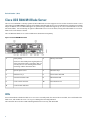
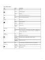
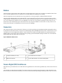
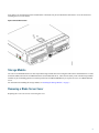
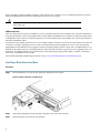
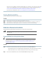
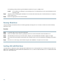
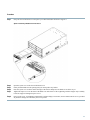
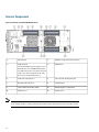
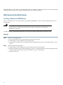
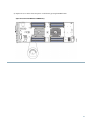
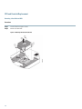
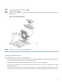
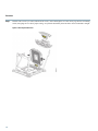
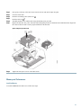
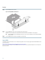
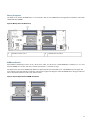
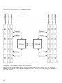
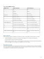
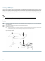
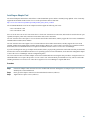
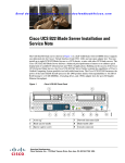
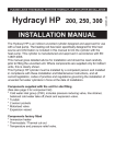
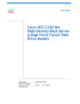
Cisco UCS B200 M4 Blade Server Installation and Service Note
Cisco UCS B200 M4 Blade Server 2
LEDs 2
Buttons 4
Connectors 4
Secure Digital (SD) Card Access 4
Storage Module 5
Removing a Blade Server Cover 5
Installing the Storage Module 7
Hard Drive Replacement 7
Blade Server Removal and Installation 9
Internal Components 12
Air Baffles 13
Diagnostics Button and LEDs 13
Working Inside the Blade Server 14
Enabling a Trusted Platform Module 26
Server Troubleshooting 27
Server Configuration 27
Physical Specifications for the Cisco UCS B200 M4 Blade Server 27
Obtaining Documentation and Submitting a Service Request 28
Revised: October 7, 2014,
Cisco UCS B200 M4 Blade Server
The Cisco UCS B200 M4 is a density-optimized, half-width blade server that supports two CPU sockets for Intel E5-2600 v3 series
CPUs and up to 24 DDR4 DIMMs. It supports one modular LOM (dedicated slot for Cisco's Virtual Interface Card) and one mezzanine
adapter. In addition, the UCS B200 M4 supports an optional storage module that supports up to 2 SAS or SATA hard drives or solid
state disks (SSDs) . You can install up to eight UCS B200 blade servers in a UCS chassis, mixing with other models or Cisco UCS
blade servers in the chassis if desired.
The UCS B200 M3 blade server is still available and is documented in separately.
Figure 1: Cisco UCS B200 M4 Front Panel
1
Asset pull tag
2
Blade ejector handle
Each server has a blank plastic tag that pulls out
of the front panel which is provided so that you
can add your own asset tracking label without
interfering with the intended air flow.
3
Ejector captive screw
4
Hard drive bay 1
5
Hard drive bay 2
6
Power button and LED
7
Network link status LED
8
Blade health LED
9
Local console connector
10
Reset button access
11
Locator button and LED
LEDs
Server LEDs indicate whether the blade server is in active or standby mode, the status of the network link, the overall health of the
blade server, and whether the server is set to give a flashing blue beaconing indication.
The removable drives also have LEDs indicating hard disk access activity and disk health.
2
Table 1: Blade Server LEDs
LED
Color
Description
Power
Off
Power off.
Green
Normal operation.
Amber
Standby.
Off
None of the network links are up.
Green
At least one network link is up.
Off
Power off.
Green
Normal operation.
Amber
Minor error.
Blinking
Amber
Critical error.
Off
Beaconing not enabled.
Link
Health
Beaconing
Blinking blue Beaconing to locate a selected blade—If the LED is not blinking, the
1 Hz
blade is not selected. You can initiate beaconing in UCS Manager or by
using the Locator button.
Activity
(Disk Drive)
Health
(Disk Drive)
Off
Inactive.
Green
Outstanding I/O to disk drive.
Flashing
Amber 4 Hz
Rebuild in progress. Health LED will flash in unison.
Flashing
Amber 4 hz
Identify drive active.
Off
Can mean either no fault detected or the drive is not installed.
Flashing
Amber 4 hz
Identify drive active. If the Activity LED is also flashing amber, a drive
rebuild is in progress.
Amber
Fault detected.
3
Buttons
The Reset button is just inside the chassis and must be pressed using the tip of a paper clip or a similar item. Hold the button down
for five seconds, and then release it to restart the server if other methods of restarting are not working.
The beaconing function for an individual server may get turned on or off by pressing the combination button and LED.
The power button and LED allows you to manually take a server temporarily out of service but leave it in a state where it can be
restarted quickly. If the desired power state for a service profile associated with a blade server or an integrated rack-mount server is
set to "off", using the power button or Cisco UCS Manager to reset the server will cause the desired power state of the server to
become out of sync with the actual power state and the server may unexpected shutdown at a later time. To safely reboot a server
from a power-down state, use the Boot Server action in Cisco UCS Manager.
Connectors
The console port allows a direct connection to a blade server to allow operating system installation and other management tasks to
be done directly rather than remotely. The port uses the KVM dongle cable (N20-BKVM) which provides a connection into a Cisco
UCS blade server; it has a DB9 serial connector, a VGA connector for a monitor, and dual USB ports for a keyboard and mouse.
With this cable, you can create a direct connection to the operating system and the BIOS running on a blade server. A KVM cable
ships standard with each blade chassis accessory kit.
Figure 2: KVM Cable for Blade Servers
1
Connector to blade server slot
3
VGA connection for a monitor
2
DB9 serial connector
4
2-port USB connector for a mouse and keyboard
Secure Digital (SD) Card Access
SD card slots are provided and one or two SD cards can be populated. If two SD cards are populated, they can be used in a mirrored
mode.
The SD cards UCS-SD-32G-S and UCS-SD-64G-S can be used to store operating system boot images or other information. Once
the server has been removed from the chassis, you can access the SD card slots by rotating the latch up so that it does not cover the
4
slots. Remove or insert the SD cards as needed. Either or both slots may be used. Rotate the latch down to cover the slots before
installing the server in the chassis.
Figure 3: SD Card Slot Locations
Storage Module
The Cisco UCS B200 M4 blade server has an optional storage module that can be configured with SAS or SATA hard drives or solid
state disks (SSDs). Because the UCS B200 M4 can be used without disk drives, it does not necessarily come with the storage module
installed. A pair of blanking panels (two with this product ID: UCSB-LSTOR-BK) may be in place on a new UCS B200 M4 blade
server.
For information on installing the storage module, see Installing the Storage Module, on page 7.
Removing a Blade Server Cover
Replacing the cover is the reverse of removing the cover.
5
Procedure
Step 1
Step 2
Press and hold the button down as shown in the figure below.
While holding the back end of the cover, pull the cover back and then up.
Figure 4: Opening a Cisco UCS B200 M4 Blade Server
6
Installing the Storage Module
Procedure
Step 1
Step 2
Place the storage module over the two standoff posts on the motherboard at the front of the server.
Press down on the drive bay cage where it is labeled "Press Here to Install" until the storage module clicks into place.
Figure 5: Storage Module
Step 3
Using a Phillips-head screwdriver, tighten the four screws to secure the storage module. The locations of the screws are
labeled "Secure Here."
Hard Drive Replacement
The RAID storage module has two front-accessible drive bays that support hot-swappable, 2.5 inch drives. If you purchased the UCS
B200 M4 blade server without the storage module configured as a part of the system, a pair of blanking panels (UCSB-LSTOR-BK)
may be in place. These panels should be removed before installing a hard drive, but should remain in place to ensure proper cooling
and ventilation if the drive bay is unused .
You can remove and install blade server hard drives without removing the blade server from the chassis.
The drives supported in this blade server come with the drive sled attached. Spare drive sleds are not available. A list of currently
supported drives is in the specification sheets at: http://www.cisco.com/en/US/products/ps10280/products_data_sheets_list.html
7
Before upgrading or adding an HDD to a running system, check the service profile in Cisco UCS Manager and make sure the new
hardware configuration will be within the parameters allowed by the service profile.
To prevent ESD damage, wear grounding wrist straps during these procedures and handle modules by the
carrier edges only.
Caution
RAID Considerations
If the drive being replaced was part of a RAID array, Cisco recommends using a new drive of identical size, model, and manufacturer
to replace the failed drive. This recommendation comes from the industry standard practice of using drives of the same capacity when
creating RAID volumes. If drives of different capacities are used, the useable portion of the smallest drive will be used on all drives
that make up the RAID volume.
If you need to move a RAID volume from one server to another, both the old and new servers for the cluster must use the same LSI
controller. For example, migrating from a server with an LSI SAS1064E controller (B200 M2) to a server with a LSI SAS2008
MegaRAID controller (B200 M3) is not supported. Similarly, migrating a RAID controller volume from a UCS B200 M4 to a UCS
B420 M3 is not supported. However, migrating the RAID volume with LSI controllers is supported if you are migrating from a UCS
B200 M3 to a UCS B200 M4 blade server and running one of the following operating systems: RHEL 6.5, RHEL 7.0, Windows
Server 2012, and Windows Server 2012 R2.
For hard disk and RAID troubleshooting information, see the Cisco UCS Manager B-Series Troubleshooting Guide.
Installing a Blade Server Hard Drive
Procedure
Step 1
Place the hard drive lever into the open position by pushing the release button.
Figure 6: Installing a Hard Drive in a Blade Server
Step 2
Step 3
8
Gently slide the hard drive into the opening in the blade server until it seats into place.
Push the hard drive lever into the closed position.
You can use Cisco UCS Manager to format and configure RAID services. For details, see the Configuration Guide for the
version of Cisco UCS Manager that you are using. The configuration guides are available at the following URL: http://
www.cisco.com/en/US/products/ps10281/products_installation_and_configuration_guides_list.html
If you need to move a RAID cluster, see the Cisco UCS Manager B-Series Troubleshooting Guide.
Removing a Blade Server Hard Drive
To remove a hard drive from a blade server, follow these steps:
Procedure
Step 1
Step 2
Step 3
Push the button to release the ejector, and then pull the hard drive from its slot.
Place the hard drive on an antistatic mat or antistatic foam if you are not immediately reinstalling it in another server.
Install a hard disk drive blank faceplate to keep dust out of the blade server if the slot will remain empty.
Blade Server Removal and Installation
Before performing any internal operations on this blade server, you must remove it from the chassis.
To prevent ESD damage, wear grounding wrist straps during these procedures and handle modules by the
carrier edges only.
Caution
Powering Off Blade Servers Using the Power Button
Tip
You can also shut the server down remotely using Cisco UCS Manager. For details, see the Configuration
Guide for the version of Cisco UCS Manager that you are using. The configuration guides are available
at the following URL: http://www.cisco.com/en/US/products/ps10281/products_installation_and_
configuration_guides_list.html
Procedure
Step 1
For each server in the chassis that you want to power off, check the color of the Power Status LED.
• Green indicates that the server is running and must be shut down before it can be safely powered off. Go to Step 2.
• Amber indicates that the server is already in standby mode and can be safely powered off. Go to Step 3.
Step 2
Press and release the Power button, then wait until the Power Status LED changes to amber.
9
The operating system performs a graceful shutdown and the server goes to standby mode.
To avoid data loss or damage to your operating system, you should always invoke a graceful shutdown of the
operating system.
(Optional) If you are shutting down all blade servers in a chassis, disconnect the power cords from the chassis to completely
power off the servers.
Remove the appropriate servers from the chassis.
Caution
Step 3
Step 4
Removing a Blade Server
Using UCS Manager, decommission the server before physically removing the server. To remove a blade server from the chassis,
follow these steps:
Procedure
Step 1
Step 2
Step 3
Step 4
Step 5
Loosen the captive screw on the front of the blade.
Remove the blade from the chassis by pulling the ejector lever on the blade until it unseats the blade server.
Slide the blade part of the way out of the chassis, and place your other hand under the blade to support its weight.
Once removed, place the blade on an antistatic mat or antistatic foam if you are not immediately reinstalling it into another
slot.
If the slot is to remain empty, install a blank faceplate (N20-CBLKB1) to keep dust out of the chassis.
Installing a Half-width Blade Server
UCS B200 M4, UCS B200 M3, and UCS B22 M3 half-width blade servers are interoperable in a UCS chassis with any other UCS
blade servers, including prior generation B200 M2 and B200 M1 servers, or other UCS B-Series blade servers. To install a half-width
blade server, follow these steps:
10
Procedure
Step 1
Grasp the front of the blade server and place your other hand under the blade to support it.
Figure 7: Positioning a Blade Server in the Chassis
Step 2
Step 3
Step 4
Step 5
Step 6
Open the ejector lever in the front of the blade server.
Gently slide the blade into the opening until you cannot push it any farther.
Press the ejector lever so that it catches the edge of the chassis and presses the blade server all the way in.
Tighten the captive screw on the front of the blade to no more than 3 in-lbs. Tightening with bare fingers only is unlikely
to lead to stripped or damaged captive screws.
Power on the server. UCS Manager automatically reacknowledges, reassociates, and recommissions the server, provided
any hardware changes are allowed by the service profile.
11
Internal Components
Figure 8: Inside View of the UCS B200 M4 Blade Server
1
SD card slots
2
Modular storage subsystem connector
3
USB connector
4
DIMM slots
An internal USB 2.0 port is supported. A 16
GB USB drive (UCS-USBFLSHB-16GB)
is available from Cisco. A clearance of 0.950
inches (24.1 mm) is required for the USB
device to be inserted and removed.
5
Front heat sink and CPU 1
6
CPU heat sink install guide pins
7
Rear heat sink and CPU 2
8
CMOS battery
9
Trusted Platform Module (TPM)
10
DIMM diagnostic LED button
11
Adapter slot 1
12
Adapter slot 2
Note
12
When the storage module is installed, the USB connector is underneath it. Use the small cutout opening
in the storage module to visually determine the location of the USB connector when you need to insert it.
Air Baffles
The air baffles direct and improve air flow for the server components. Two identical baffles ship with each B200 M4 server. No tools
are necessary to install them, just place them over the DIMMs as shown, with the holes in the center of the baffles aligned with the
corresponding motherboard standoffs.
Figure 9: Cisco UCS B200 M3 Air Baffles
Diagnostics Button and LEDs
At blade start-up, POST diagnostics test the CPUs, DIMMs, HDDs, and adapter cards, and any failure notifications are sent to UCS
Manager. You can view these notifications in the System Error Log or in the output of the show tech-support command. If errors
are found, an amber diagnostic LED also lights up next to the failed component. During run time, the blade BIOS, component drivers,
and OS all monitor for hardware faults and will light up the amber diagnostic LED for a component if an uncorrectable error or
correctable errors (such as a host ECC error) over the allowed threshold occur.
LED states are saved, and if you remove the blade from the chassis the LED values will persist for up to 10 minutes. Pressing the
LED diagnostics button on the motherboard causes the LEDs that currently show a component fault to light for up to 30 seconds for
easier component identification. LED fault values are reset when the blade is reinserted into the chassis and booted, and the process
begins from its start.
If DIMM insertion errors are detected, they may cause the blade discovery to fail and errors will be reported in the server POST
information, which is viewable using the UCS Manager GUI or CLI. UCS blade servers require specific rules to be followed when
populating DIMMs in a blade server, and the rules depend on the blade server model. Refer to the documentation for a specific blade
server for those rules.
13
HDD status LEDs are on the front face of the HDD. Faults on the CPU, DIMMs, or adapter cards also cause the server health LED
to light solid amber for minor error conditions or blinking amber for critical error conditions.
Working Inside the Blade Server
Installing a Motherboard CMOS Battery
All Cisco UCS blade servers use a CR2032 battery (Cisco PID N20-MBLIBATT=) to preserve BIOS settings while the server is
powered down.
There is danger of explosion if the battery is replaced incorrectly. Replace the battery only with the same
or equivalent type recommended by the manufacturer. Dispose of used batteries according to the
manufacturer’s instructions.
Warning
To install or replace a motherboard complementary metal-oxide semiconductor (CMOS) battery, follow these steps:
Procedure
Step 1
Remove the old CMOS battery:
a) Power off the blade, remove it from the chassis, and remove the top cover.
b) Push the battery socket retaining clip away from the battery.
c) Lift the battery from the socket. Use needle-nose pliers to grasp the battery if there is not enough clearance for your
fingers.
Step 2
Install a motherboard CMOS battery:
a) Push the battery socket retaining clip away from where the battery fits in the housing.
b) Insert the new battery into the socket with the battery’s positive (+) marking facing away from the retaining clip. Ensure
that the retaining clip can click over the top of the battery to secure it in the housing.
c) Replace the top cover.
14
d) Replace the server in the chassis and power on the blade by pressing the Power button.
Figure 10: Location of the Motherboard CMOS Battery
15
CPU and Heatsink Replacement
Removing a Heat Sink and CPU
Procedure
Step 1
Step 2
Unscrew the four captive screws.
Remove the heat sink.
Figure 11: Removing the Heat Sink and CPU
16
Step 3
Unhook the self-loading socket (SLS) lever
Step 4
Unhook the SLS lever .
Grasp the sides of the CPU carrier (indicated by the arrows in the illustration) and swing it into a standing position in the
SLS plug seat.
Step 5
.
Figure 12: CPU Carrier and SLS Plug Seat
Step 6
Pull the CPU carrier up and out of the SLS plug seat.
Installing a New CPU and Heat Sink
Before installing a new CPU in a server, verify the following:
• The CPU is supported for that given server model. This may be verified through the server Technical Specifications ordering
guides or by the relevant release of the Cisco UCS Capability Catalog.
• A BIOS update is available and installed that supports the CPU and the given server configuration.
• If the server will be managed by Cisco UCS Manager, the service profile for this server in Cisco UCS Manager will recognize
and allow the new CPU.
• The CPUs and heat sinks are different and must be installed in the correct location. The front heat sink and CPU 1 can only be
installed in the front of the blade server and the rear heat sink and CPU 2 can only be installed in the rear of the blade server.
17
Procedure
Step 1
Hold the CPU carrier by its sides (indicated b the arrows). Insert and align the two CPU carrier pegs into the self-loading
socket (SLS) plug seat. To ensure proper seating, verify that the horizontal yellow line below the word ALIGN is straight.
Figure 13: Inserting the CPU Carrier
18
Step 2
Step 3
Step 4
Press gently on the top of the CPU carrier from the exterior side until it snaps into place.
Close the socket latch.
Step 5
Hook the SLS lever .
Thermally bond the CPU and heat sink using the thermal grease provided.
Replace the heat sink. The yellow CPU heat sink install guide pins that are attached to the motherboard must align with
the cutout on the heat sink to ensure proper installation of the heat sink.
Step 6
Step 7
Hook the self-loading socket (SLS) lever .
Figure 14: Replacing the Heat Sink
Step 8
Tighten the four captive screws in the order shown.
Memory and Performance
Installing Memory
To install a DIMM into the blade server, follow these steps:
19
Procedure
Step 1
Open both DIMM connector latches.
Figure 15: Installing DIMMs in the Blade Server
Step 2
Press the DIMM into its slot evenly on both ends until it clicks into place.
DIMMs are keyed, if a gentle force is not sufficient, make sure the notch on the DIMM is correctly aligned.
Be sure that the notch in the DIMM aligns with the slot. If the notch is misaligned you may damage the DIMM,
the slot, or both.
Press the DIMM connector latches inward slightly to seat them fully.
Note
Step 3
Supported DIMMs
The DIMMs supported in this blade server are constantly being updated. A list of currently supported and available DIMMs is in the
specification sheets at:
http://www.cisco.com/en/US/products/ps10280/products_data_sheets_list.html
Cisco does not support third-party memory DIMMs, and in some cases their use may irreparably damage the server and require an
RMA and down time.
20
Memory Arrangement
The blade server contains 24 DIMM slots—12 for each CPU. Each set of 12 DIMM slots is arranged into four channels, where each
channel has three DIMMs.
Figure 16: Memory Slots In the Blade Server
1
Channels A-D for CPU 1
2
Channels E-H for CPU 2
DIMMs and Channels
Each channel is identified by a letter—A, B, C, D for CPU1, and E, F, G, H for CPU 2. Each DIMM slot is numbered 1, 2, or 3. Note
that each DIMM slot 1 is blue, each slot 2 is black, and each slot 3 is off-white or beige.
The figure below shows how DIMMs and channels are physically laid out on the blade server. The DIMM slots in the upper and
lower right are associated with the second CPU (CPU shown on right in the diagram), while the DIMM slots in the upper and lower
left are associated with the first CPU (CPU shown on left).
Figure 17: Physical Representation of DIMMs and Channels
21
The figure below shows a logical view of the DIMMs and channels.
Figure 18: Logical Representation of DIMMs and Channels
DIMMs can be used in the blade server in a one DIMM per Channel (1DPC) configuration, in a two DIMMs per Channel (2DPC)
configuration, or a three DIMMs per Channel (3DPC) configuration.
Each CPU in a Cisco UCS B200 M4 blade server supports four channels of three memory slots each. In a 1 DPC configuration,
DIMMs are in slot 1 only. In a 2 DPC configuration, DIMMs are in both slot 1 and slot 2. In a 3 DPC configuration, DIMMs are in
slot 1, slot 2, and slot 3.
22
Table 2: Supported DIMM Population Order
DIMMs per CPU
CPU 1 installed slots
CPU 2 installed slots
1
A1
E1
2
A1, B1
E1, F1
3
A1, B1, C1
E1, F1, G1
4 (Blue slots)
A1, B1, C1, D1
E1, F1, G1, H1
5
A1, B1, C1, D1, A2
E1, F1, G1, H1, E2
6
A1, B1, C1, D1, A2, B2
E1, F1, G1, H1, E2, F2
7
A1, B1, C1, D1, A2, B2, C2
E1, F1, G1, H1, E2, F2, G2
8 (Blue and black slots)
A1, B1, C1, D1, A2, B2, C2, D2
E1, F1, G1, H1, E2, F2, G2, H2
9
A1, B1, C1, D1, A2, B2, C2, D2,A3
E1, F1, G1, H1, E2, F2, G2, H2, E3
10
A1, B1, C1, D1, A2, B2, C2, D2,A3, B3
E1, F1, G1, H1, E2, F2, G2, H2, E2, F3
11
A1, B1, C1, D1, A2, B2, C2, D2,A3, B3, C3
E1, F1, G1, H1, E2, F2, G2, H2, E3, F3,
G3
12 (Blue, black and beige slots) A1, B1, C1, D1, A2, B2, C2, D2,A3, B3, C3,
D3
E1, F1, G1, H1, E2, F2, G2, H2, E3, F3,
G3, H3
Memory Performance
When considering the memory configuration of your blade server, there are several things you need to consider. For example:
• When mixing DIMMs of different densities, the highest density DIMM goes in slot 1 then in descending density.
• Your selected CPU(s) can have some affect on performance.
• DIMMs can be run in a 1DPC, a 2DPC, or a 3DPC configuration. 1 DPC and 2DPC can provide the maximum rated speed that
the CPU and DIMMs are rated for. 3DPC causes the DIMMs to run at a slower speed.
Memory Mirroring and RAS
The Intel CPUs within the blade server support memory mirroring only when an even number of Channels are populated with DIMMs.
If one or three channels are populated with DIMMs, memory mirroring is automatically disabled. Furthermore, if memory mirroring
is used, DRAM size is reduced by 50 percent for reasons of reliability.
23
Installing a mLOM Adapter
The Cisco VIC 1340 and VIC 1240 are specialized modular LAN on Motherboard (mLOM) adapters that provide dual 2 x 10 Gb of
Ethernet/ or Fiber Channel over Ethernet (FCoE) connectivity to each chassis. They plug into the dedicated mLOM connector only,
and they are the only adapters that can be plugged into the mLOM connector. They provide connectivity through Cisco UCS 6100
and 6200 Series Fabric Interconnects. The Cisco VIC 1200 Series (1240 and 1280) is compatible in UCS domains that implement
both UCS 6100 and 6200 Series Fabric Interconnects. However, the Cisco VIC 1300 Series (1340 and 1380) is compatible only with
the UCS 6200 Series Fabric Interconnects.
Note
You must remove the adapter card to service the mLOM.
To install an mLOM on the blade server, follow these steps:
Procedure
Step 1
Position the mLOM’s board connector above the motherboard connector and align the captive screw to the standoff post
on the motherboard.
Step 2
Firmly press the mLOM’s board connector into the motherboard connector.
Tighten the captive screw.
Tip
To remove an mLOM, reverse the above procedure. You might find it helpful when removing the connector from
the motherboard to gently rock the board along the length of the connector until it loosens.
Step 3
Figure 19: Installing an mLOM
24
Installing an Adapter Card
The network adapters and interface cards all have a shared installation process and are constantly being updated. A list of currently
supported and available models for this server is in the specification sheets at this URL:
http://www.cisco.com/en/US/products/ps10280/products_data_sheets_list.html
The UCS B200 M4 blade server has two adapter slots that support the following VIC cards:
• VIC 1340 and VIC 1380
• VIC 1240 and VIC 1280
Slot 1 is for the VIC 1340 or VIC 1240 cards. Slot 2 is for the VIC 1380 and VIC 1280 cards, and can also be used for the VIC port
expander, third-party CNA cards, and non-I/O mezzanine cards, such as Fusion IO.
The VIC 1340 and VIC 1380 require a Cisco UCS 6200 Series Fabric Interconnect, and they support the Cisco Nexus 2208XP and
2204XP Fabric Extender (FEX) modules.
The VIC 1240 and VIC 1280 support Cisco UCS 6200 and 6100 Series Fabric Interconnects, and they support the Cisco Nexus
2208XP, 2204XP, and 2104XP Fabric Extender (FEX) modules. When a VIC 1240 or 1280 is used with a UCS 6100 Series Fabric
Interconnect, the UCS B200 M4 blade server requires a minimum software release of 2.2 for Cisco UCS Manager.
If you are switching from one type of adapter card to another, before you physically perform the switch make sure that you download
the latest device drivers and load them into the server’s operating system. For more information, see the firmware management chapter
of one of the Cisco UCS Manager software configuration guides.
The Cisco Fusion-io Drive mezzanine adapter cards can be installed and removed using the same procedures. Using these drives in
a B200 M4 blade server requires the presence of a VIC 1340 or VIC 1240 mLOM to provide blade I/O. They will not work in M1
and M2 generations Cisco UCS servers. These drives appear in Cisco UCS Manager as regular SSD drives.
Procedure
Step 1
Step 2
Step 3
Position the adapter board connector above the motherboard connector and align the two adapter captive screws to the
standoff posts on the motherboard.
Firmly press the adapter connector into the motherboard connector (callout 2).
Tighten the two captive screws (callout 3).
25
Tip
Removing an adapter card is the reverse of installing it. You might find it helpful when removing the connector
from the motherboard to gently rock the board along the length of the connector until it loosens.
Figure 20: Installing an Adapter Card
Enabling a Trusted Platform Module
The Trusted Platform Module (TPM, Cisco Product ID UCSX-TPM2-001) is a component that can securely store artifacts used to
authenticate the server. These artifacts can include passwords, certificates, or encryption keys. A TPM can also be used to store
platform measurements that help ensure that the platform remains trustworthy. Authentication (ensuring that the platform can prove
that it is what it claims to be) and attestation (a process helping to prove that a platform is trustworthy and has not been breached)
are necessary steps to ensure safer computing in all environments.
A TPM is a factory-configurable option for this server. It is a requirement for the Intel Trusted Execution Technology (TXT) security
feature, which must be enabled in the BIOS settings for a server equipped with a TPM. A TPM can not be moved from one server
to another.
26
Procedure
Step 1
Step 2
Step 3
Step 4
Step 5
Step 6
Step 7
Enable Quiet Mode in the BIOS policy of the server’s service profile.
Establish a direct connection to the server, either by connecting a keyboard, monitor, and mouse to the front panel using
a KVM dongle (N20-BKVM) or by other means.
Reboot the server.
Press F2 during reboot to enter the BIOS setup screens.
On the Advanced tab, select Trusted Computing and press Enter.
Set the TPM Support option to Enable.
Press F10 to save and exit. Allow the server to finish booting.
Server Troubleshooting
For general troubleshooting information, see the see the Cisco UCS Manager B-Series Troubleshooting Guide.
Server Configuration
Cisco UCS blade servers are intended to be configured and managed using Cisco UCS Manager. For details, see the Configuration
Guide for the version of Cisco UCS Manager that you are using. The configuration guides are available at the following URL: http:/
/www.cisco.com/en/US/products/ps10281/products_installation_and_configuration_guides_list.html
Physical Specifications for the Cisco UCS B200 M4 Blade Server
Specification
Value
Height
1.95 inches (50 mm)
Width
8.00 inches (203 mm)
Depth
24.4 inches (620 mm)
Weight
Base server weight = 9.51 lbs (4.31 kg) (no HDDs, no CPUs,
no DIMMs, no mezzanine adapters or memory)
Minimally configured server = 11.29 lbs (5.12 kg) (no HDDs,
1 CPU, 8 DIMMs, VIC 1340/1240 but no mezzanine adapter)
Fully configured server = 15.98 lbs (7.25 kg) (2 HDDs, 2
CPUs, 24 DIMMs, VIC 1340/1240 and mezzanine adapter
both populated)
27
Obtaining Documentation and Submitting a Service Request
For information on obtaining documentation, submitting a service request, and gathering additional information, see the monthly
What's New in Cisco Product Documentation, which also lists all new and revised Cisco technical documentation.
Subscribe to the What's New in Cisco Product Documentation as a Really Simple Syndication (RSS) feed and set content to be
delivered directly to your desktop using a reader application. The RSS feeds are a free service and Cisco currently supports RSS
version 2.0.
Follow Cisco UCS Docs on Twitter to receive document update notifications.
28
THE SPECIFICATIONS AND INFORMATION REGARDING THE PRODUCTS IN THIS MANUAL ARE SUBJECT TO CHANGE WITHOUT NOTICE. ALL STATEMENTS,
INFORMATION, AND RECOMMENDATIONS IN THIS MANUAL ARE BELIEVED TO BE ACCURATE BUT ARE PRESENTED WITHOUT WARRANTY OF ANY KIND,
EXPRESS OR IMPLIED. USERS MUST TAKE FULL RESPONSIBILITY FOR THEIR APPLICATION OF ANY PRODUCTS.
THE SOFTWARE LICENSE AND LIMITED WARRANTY FOR THE ACCOMPANYING PRODUCT ARE SET FORTH IN THE INFORMATION PACKET THAT SHIPPED WITH
THE PRODUCT AND ARE INCORPORATED HEREIN BY THIS REFERENCE. IF YOU ARE UNABLE TO LOCATE THE SOFTWARE LICENSE OR LIMITED WARRANTY,
CONTACT YOUR CISCO REPRESENTATIVE FOR A COPY.
The following information is for FCC compliance of Class A devices: This equipment has been tested and found to comply with the limits for a Class A digital device, pursuant to part 15
of the FCC rules. These limits are designed to provide reasonable protection against harmful interference when the equipment is operated in a commercial environment. This equipment
generates, uses, and can radiate radio-frequency energy and, if not installed and used in accordance with the instruction manual, may cause harmful interference to radio communications.
Operation of this equipment in a residential area is likely to cause harmful interference, in which case users will be required to correct the interference at their own expense.
The following information is for FCC compliance of Class B devices: This equipment has been tested and found to comply with the limits for a Class B digital device, pursuant to part 15
of the FCC rules. These limits are designed to provide reasonable protection against harmful interference in a residential installation. This equipment generates, uses and can radiate radio
frequency energy and, if not installed and used in accordance with the instructions, may cause harmful interference to radio communications. However, there is no guarantee that interference
will not occur in a particular installation. If the equipment causes interference to radio or television reception, which can be determined by turning the equipment off and on, users are
encouraged to try to correct the interference by using one or more of the following measures:
• Reorient or relocate the receiving antenna.
• Increase the separation between the equipment and receiver.
• Connect the equipment into an outlet on a circuit different from that to which the receiver is connected.
• Consult the dealer or an experienced radio/TV technician for help.
Modifications to this product not authorized by Cisco could void the FCC approval and negate your authority to operate the product
The Cisco implementation of TCP header compression is an adaptation of a program developed by the University of California, Berkeley (UCB) as part of UCB’s public domain version
of the UNIX operating system. All rights reserved. Copyright © 1981, Regents of the University of California.
NOTWITHSTANDING ANY OTHER WARRANTY HEREIN, ALL DOCUMENT FILES AND SOFTWARE OF THESE SUPPLIERS ARE PROVIDED "AS IS" WITH ALL FAULTS.
CISCO AND THE ABOVE-NAMED SUPPLIERS DISCLAIM ALL WARRANTIES, EXPRESSED OR IMPLIED, INCLUDING, WITHOUT LIMITATION, THOSE OF
MERCHANTABILITY, FITNESS FOR A PARTICULAR PURPOSE AND NONINFRINGEMENT OR ARISING FROM A COURSE OF DEALING, USAGE, OR TRADE PRACTICE.
IN NO EVENT SHALL CISCO OR ITS SUPPLIERS BE LIABLE FOR ANY INDIRECT, SPECIAL, CONSEQUENTIAL, OR INCIDENTAL DAMAGES, INCLUDING, WITHOUT
LIMITATION, LOST PROFITS OR LOSS OR DAMAGE TO DATA ARISING OUT OF THE USE OR INABILITY TO USE THIS MANUAL, EVEN IF CISCO OR ITS SUPPLIERS
HAVE BEEN ADVISED OF THE POSSIBILITY OF SUCH DAMAGES.
Any Internet Protocol (IP) addresses and phone numbers used in this document are not intended to be actual addresses and phone numbers. Any examples, command display output, network
topology diagrams, and other figures included in the document are shown for illustrative purposes only. Any use of actual IP addresses or phone numbers in illustrative content is unintentional
and coincidental.
Cisco and the Cisco logo are trademarks or registered trademarks of Cisco and/or its affiliates in the U.S. and other countries. To view a list of Cisco trademarks, go to this URL: http://
www.cisco.com/go/trademarks. Third-party trademarks mentioned are the property of their respective owners. The use of the word partner does not imply a partnership
relationship between Cisco and any other company. (1110R)
© 2014-
Cisco Systems, Inc. All rights reserved.
Americas Headquarters
Cisco Systems, Inc.
San Jose, CA 95134-1706
USA
Asia Pacific Headquarters
Cisco Systems (USA) Pte. Ltd.
Singapore
Europe Headquarters
Cisco Systems International BV
Amsterdam, The Netherlands
Cisco has more than 200 offices worldwide. Addresses, phone numbers, and fax numbers are listed on the
Cisco Website at www.cisco.com/go/offices.