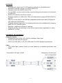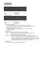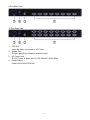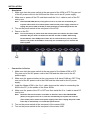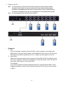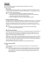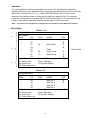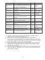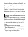
1
19" TFT LCD CONSOLE WITH KVM SWITCH (8-PORT/16-PORT) User Manual DS-72303GE / DS-72303US DS-72402GE / DS-72402US LCD MONITOR SPECIFICATIONS Size Screen Type Contrast Brightness View Angle Resolution Response Time Display Color 19 inch TFT 700:1 300 cd/m2 160° 1280x1024@75Hz 6 ms 16.2 M OPERATION Keypad Define Power key: Use this key to turn on or off the LCD monitor. Menu key: Use this key to open the OSD menu and enter to next menu or to highlight a confirmed function. Up key: Use this key to highlight an item in the menu, to move a highlighted function up, or to increase the numeric value (parameter) in a certain menu. Down key: Use this key to highlight an item in the menu, to move a highlighted function down, or to decrease the numeric value (parameter) in a certain menu. Auto key: Use this key to automatically adjust the image position and phase, and return to the previous menu or to exit a highlight item. If the screen is not in a full screen graphic mode (such as in a DOS) or is connected with an allocator, the position of the appeared image may be adjusted automatically and then deviated. By then, it is necessary to enter into the OSD menu to manually adjust the level or vertical position and phase. -2- OSD Control Function List 1. Color: Contrast Brightness Color Adjust Color Temp.: 9300, 6500, 5800, 5RGB, USER Exit 2. Image Setting: Clock Phase Gamma Sharpness Exit 3. Position: H.Position V.Position Exit 4. OSD Menu: OSD H.Pos OSD V.Pos OSD Timer Exit 5. Language: English, Français, Deutsch, Español, 繁體中文, 简体中文, 日本語 6. Misc.: Signal Source Reset Factory Mode Exit 7. Exit -3- BRIEF INTRODUCTION The KVM Switch allows you to control several sets of personal computers by a keyboard, a mouse and a monitor. In the meantime, you just need to connect the cable and turn on the power to control up to 256 sets of personal computers without installing any additional interface card or software. Easy Installation The 3-in-1 CPU Connector (VGA, Keyboard and Mouse) can save the installation time and space and assure the correct signals. The universal AC power input of 100~240VAC, 50Hz~60Hz saves you the trouble of finding the space for installing the Power Adaptor. You can install a cascade to facilitate expansions or transportation without requiring a cascade cable or changing the KVM configurations. On-Screen Display (OSD) Menu The embedded OSD control module lets you name the PC and KVM and modify the KVM configuration, and the security mode can prevent others from turning on the KVM by mistake and switching the linked PC from the OSD. Most conveniently, the OSD not only supports keyboard operations, but also supports mouse clicking. Enhanced Video Quality The special video circuit design supports resolution up to 1280x1024, 75Hz, and also keeps the same quality under the Cascade architecture. PACKAGE INSIDE KVM Switch USER Manual Power Cord F/W Update Cable Rack-Mount Brackets Screws (for Brackets) Key x1 x1 x1 x1 x2 x 12 x2 -4- FEATURES ‧ ‧ ‧ ‧ ‧ ‧ ‧ ‧ ‧ ‧ The keyboard, mouse and 19” LCD monitor were built-in on the KVM switch. Standalone machine controls up to 4/8/16 sets of PCs. Cascade controls 64/128/256 sets of PCs. Through OSD, you can use the hot key, mouse clicking and push button on front panel to switch PCs. Monitors PC status by Auto Scan function. Supports resolution of 1280x1024, 75Hz and independently supports EDID & DDC2 of each PC. Each Port on the panel of the KVM has independent push buttons and LED lamps for easy switch and identification. Complies with the height of the 1U chassis specification and installable with a hanging stand into a 19” chassis system. Requires no additional software or hardware. Supports hot plug; not necessary to turn off the original system regardless of a newly installed PC or KVM. EQUIPMENT REQUIREMENTS Computer System ‧ A Supported VGA, SVGA, XGA, SXGA or Multisync Video Card. ‧ A PS/2 (mini-DIN 6Pin) Mouse port. ‧ A PS/2 (mini-DIN 6Pin) or AT (5-Pin DIN) with AT-to-PS/2 Adaptor Keyboard port. Cable ‧ 3-in-1 KVM Cable; please contact your local distributor for detailed specification and length. Connected to CPU port of KVM Connected to Console port of PC or Slave KVM -5- SPECIFICATIONS CPU Connecter 3-in-1 HD-15 (Female) Monitor Console Mouse Connector Keyboard Port Selection Keys on Front Panel Port LEDs Power OSD Video Resolution Dimensions Weight Operating Temp Storage Temp Humidity 8-port 16-port 8 16 19” TFT LCD Touch pad module Standard 104 keys 8 16 8 1 16 1 Built-in 1280x1024@75Hz 600x450x48 mm 13.35 Kg 13.4 Kg 5-40°C -20~60°C 10~80%RH, non-condensing -6- CONFIGURATION 8-Port Front View 16-Port Front View 1. Port Selection Switches Press the push button to directly switch to the corresponding PC. • In the cascade architecture, if the port is connected to KVM but not PC, then the push button will not respond. • Simultaneously press Push Buttons 1 and 2 to directly enter the OSD Control Mode. 2. Port LEDs These Port LEDs are built in the Port Selection Switches. Online: A green light indicates that the PC or KVM connected to the corresponding port is on and operating. Selected: A red light indicates the situation of being connected to the port. • If a port is connected to KVM, then the red light of that port will not on. • Besides the special mode, the whole system architecture only has one red light (indicating that the Console is connecting to the PC) or has no red light (when powering on the KVM for the first time.) 3. Power LED The blue light indicates that the KVM is operating. -7- 8-Port Rear View 16-Port Rear View 1. CPU Port Install the cable connected to a PC here. 2. Update Port The port provides a firmware update function. 3. AC Power Jack The AC Power is applicable for 100~240VAC, 50Hz~60Hz 4. Power Switch Power On/Off the LCD KVM. -8- INSTALLATION • Standalone 1. Make sure that the power switch at the rear panel of the KVM is OFF. Plug an end of the AC power cord into the KVM and the other end to an AC power supply. 2. Make sure to power off the PC and then install the 3-in-1 cable to each of the PC one by one. Note: If the ON-LINE LED (Green) of any port of a PC is on, then we recommend you to power off such PC (Turn off the power switch of the power supply of the PC or unplug the power cable of the PC) or wait till Step 4 to install that particular PC. 3. Turn on the power switch at the rear panel of the KVM. 4. Power on the PC. Note: It is not necessary to power down the whole system for install a new PC or KVM thereafter. All you need is to make sure that the new PC or KVM is OFF during the installation. If the KVM powers down due to external factors (such as power failure or the power of the KVM is turned off), we recommend you to reinstall the whole system. • Connection in Series 1. Make sure that the power switch at the rear panel of the Master KVM is OFF. Plug one end of the AC power cord to the KVM and the other end to the AC power supply. 2. Make sure the power switches at the rear panels of all slave KVMs are OFF. Plug one end of the AC power cord to the KVM and the other end to the AC power supply. 3. Install the Master KVM to the 3-in-1 cable (same as the cable for connecting the KVM to the PC) in the middle of the Slave KVMs. 4. Make sure the power of the PC is OFF and then install the 3-in-1 cable to each PC one by one. Note: Install the PCs on the master or the PCs on the Slave first. If the ON-LINE LED (Green) of any port of a PC is on, then we recommend you to power off such PC (Turn off the power switch of the power supply of the PC or unplug the power cable of the PC) or wait till Step 7 to install that particular PC. 5. Turn on the power switch at the rear panel of the master KVM. 6. Turn on the power switch at the rear panel of the slaver KVM. -9- 7. Power on the PC. Note It is not necessary to power down the whole system for install a new PC or KVM thereafter. All you need is to make sure that the new PC or KVM is OFF during the installation. If the KVM powers down due to external factors (such as power failure or the power of the KVM is turned off), we recommend you to reinstall the whole system. Note: It is noteworthy that there are two levels available. • Expansion 1. PCs It is not necessary to power down the KVM or other computer connected to the KVM system. You only need to power off the desired PC and connect the PC to the CPU port of the KVM in parallel by the 3-in-1 cable, and then power on the PC. 2. Slave KVM Make sure the power switch at the rear panel of the KVM is OFF. Use the AC power cord (3-in-1 cable) to connect the console port of the slave KVM to the CPU port of the master KVM. Power on the slave KVM. For example: If you want to install one Slave KVM and three PCs, then just follow Step 2 of the foregoing method to add the slave KVM and install the PCs one by one according to Step 1. - 10 - OPERATION Port Selection The LCD KVM provides fours switching methods: Manual Key, Hot Key, Mouse Clicking and OSD. • Manual Key It is the simplest switching method. You just need to press the Port Selection Switch on the front panel of the KVM. The Selection LED (Red) is on, indicating that you are switching to the corresponding port. Note: 1. The Port Selection Switch functions only when connected to a PC. 2. If the Offline Skip of the OSD System Setting is Auto, then you cannot make any switch when pressing an offline Port Selection Switch. 3. For Auto Scan Mode, none of the Port Selection Switches functions. • Hot Key and Mouse Clicking Hot key and mouse clicking are applicable for switching a small section. You can select the SVS (Smart View Setting) from the OSD of the PC first (for a quick switch of PC) and use the keyboard (press the Ctrl key twice) or the mouse (press and hold the middle button while pressing the left or right button) to switch to the previous or next set of PC. Note: The mouse must have at least 3 keys. As far as you select a PC with the SVS, you can use this method for the switch. • OSD (On Screen Display) Press the NumLock on the keyboard twice or simultaneously press the Push Buttons 1 and 2 of the Port Selection Switch on the KVM panel to start the OSD. Use the Up, Down and Enter keys on the keyboard to switch or directly move the mouse to the target PC, and then double click the left button. Additionally, you also can use the numeric keys to enter the direct switch. For example, if you want to switch a PC to the Slave KVM port 04 under the Master KVM port 03, then you can start the OSD and then directly enter 0304. If you are using a standalone machine, then just enter the first two digits. More OSD related information are given in the following OSD sections. On Screen Display (OSD) • Start Press the NumLock twice or the Port Selection Switches 1 and 2 on the panel to enter the OSD. Note: If you have modified the Hot Key for starting the OSD and are unable to enter the OSD by pressing NumLock, then you can start the OSD by using the Port Selection Switch first, and then press F9 to enter into the System Setting to modify the options of the OSD Entry Hot Key. - 11 - • • Operation You can operate the options by keyboard or mouse. For the keyboard operation, besides the common Up and Down keys, there are special function keys such as Enter, Space Bar, Function Key (F1,F4…) under the OSD remark field. For the mouse operation, the left key refers to Enter and the right key refers to Exit. For example, move the mouse point to your desired PC, and click the left key. The selection bar will move to that position and then click the left key again for the execution. Note: You must use the keyboard to complete the two functions: Name Edit and Password. Switch Menu Master List 1 2 3 4 03-04: Mail Ser 4 List: Master PWR C# • 01 • 02 • 03 04 • 05 • 06 • 07 08 ↑↓: Move F1: Smart View F4: Auto Scan F5: Clear Name List KVM NAME Admin 04 Mail Group 08 16 Peter Web Group Data Group Space: Edit Enter: Switching F9: System Setting SVS Θ Ο Θ → Press Enter → Ο Ο Θ Esc: Exit Slave List 03-04: Mail Ser 4 List: Master PWR C# • 01 • 02 • 03 • 04 ↑↓: Move F1: Smart View F4: Auto Scan F5: Clear Name List KVM NAME Mail Ser 1 Mail Ser 2 Mail Ser 3 Mail Ser 4 Space: Edit Enter: Switching F9: System Setting - 12 - SVS Θ Θ Esc: Exit 1. This field provides the information of the currently connected PC. As shown in the figure above, 03 refers to the Port Number of the Master; 04 refers the Port Number of the Slave; and Mail Ser 4 is the name of this PC defined by Users. If a PC connects to the Master, then the number consists of the first two digits. If a User has not given a name for the PC, the name field will be blank. 2. This field shows the list of the Master KVM or a certain set of Slave KVM currently displayed on the OSD. We recommend you to give a name to the Slave KVM, or else the display after LIST: will be blank. 3. This field shows the list of connections to the KVM, and the fields are described below: PWR: It shows the status of power supply and indicates a normal power supply for the equipment (PC or KVM) connected to the CPU port. C# : It shows the channel number; the KC-1904 will display 01~04; the KC-1908 will display 01~08 and the KC-1916 will display 01~08; 09~16 (Since the screen cannot display all at a time, therefore you can use PgUp/PgDn to switch the pages). KVM: It shows the KVM model. If there is a number in this field, it shows that a set of KVM connects to this port. The number 04 indicates Port 4 and 08 indicates Port 8 and 16 indicates Port 16 and so on. Note: If the connected KVM is not on, there will have no number in this field. NAME: It shows the name of the equipment, and users can name the Slave KVM or PC on their own. There are a total of 12 characters selected from the group of “A~Z”, “a~z”, “0~9” , “+”, “-” , “*”, “/” , “=”, “[”, “]”, “,”, “.”, “:”. Note: Please use the CapsLock to toggle the upper and lower cases. SVS: It shows the Smart View Setting; use to open and Θ to close. The SVS is blank and not clickable if the KVM is connected in parallel. If this option is set to open, then you can make the switch by operating the Hot Key Switch or Mouse Clicking or selecting the option by Auto Scan. You also can use mouse to click this field. Selection BAR: It shows the selection bar (Green); you can use the ↑↓ keys on the board to move the selection bar, and the situated position indicates the selected target for giving instructions. For example, if the selection bar points at C#05 and you press Enter, then the system will switch to that particular PC or press the “Space BAR” to start editing the name. Press F4 to enable/disable the SVS option. - 13 - 4. Instruction Hint Field: ↑↓: Move; Use the ↑↓ keys on the keyboard or the mouse to move the selection bar. SPACE: Edit; The “Space BAR” on the keyboard is used to start editing the name of the PC or KVM. ESC: Exit; Use the “Esc” key on the keyboard to exit the current option or exit OSD. F4: Auto Scan; Use the F4 key to run Auto Scan, and you can set the residing time, channel display time and mode of the Auto Scan from System Setting. F9: System Setting; Use the F9 key to enter into the System Setting Menu. F5: Clear Name List; Use the F5 key to clear the values of all Name fields. If you clear the name list under the Master screen, then you will also clear the name lists under all slaves. If you clear the name list under a certain slave, then you only clear the name list under that particular Slave KVM. F1: Smart View; It switches the Smart View Setting. • System Setting Menu System Setting Channel Display Mode: Channel Display Time: Auto Scan Time: OSD Entry Hot Key: Hot Key Switching: Mouse Clicking: Beeper Sound: Offline Skip: OSD Language: Security Level: Console Lock Time: ↑↓: Move F1: Information F8: Restore Default Setting Full 5 Sec 5 Sec Number Lock OFF OFF ON Manual English None 5 Min Space: Change Esc: Exit F4: OSD Position - 14 - Item Description For Port Switching, Auto Scan and OSD Channel Display Close, the Monitor will show the Channel Mode information and mode selection. Channel Display It shows the time for displaying channel Time information. For Auto Scan, it shows the residing time Auto Scan Time for each port. Select to turn on the hot keys of the OSD OSD Entry Hot Key control screen. Turn on/off the “Ctrl” hot keys on the Hot Key Switching keyboard for switching computer functions. Turn on/off the keys of the mouse for Mouse Clicking switching computer functions. Beeper Sound Turn on/off the beeper sound function. Set the offline skip function to auto or Offline Skip manual. Default Other Selection Full 10Sec, Always, None 10Sec, 20Sec, 5 Sec 30Sec, 60Sec Scroll Lock, NumLock Shift, None 5 Sec OFF ON OFF ON ON OFF Manual Auto OSD Language Select the language for the OSD. English Security Level Select the security mode and level. None The lock time of console port. 5 Min Console Lock Time *1 Number, Name Français, Deutsch, Italiano, Español Low, High 1Min, 3Min, 10Min, 30Min, 60Min *1: You can select this option only if the Security Level is not “None”. F1: Information; It provides the model name and F/W version information, which is helpful for users to understand the updated version. F4: OSD Position; You can enter the OSD position to make adjustments; we recommend you to unify the resolution for all computer display mode, and use this function again to adjust the OSD position. You can use the Up, Down, Left or Right keys on the keyboard or a mouse to move the OSD position. F8: Restore Default Setting; Restore the factory default settings. Please note that all name lists will be cleared and the system settings are set to the default settings as shown in the table above. Esc: Exit; Exit the system setting and close the OSD. If you have made changes in this option, the system will ask whether or not you want to save the setting before the selected option is effective. - 15 - • Auto Scan Mode: You can start the OSD first and press “F4” to enter the Auto Scan Mode. If you want to scan the PC, you must use the Smart View Setting to select the Auto Scan Time in the System Setting for the residing time, which includes 5 sec, 10 sec, 20 sec, 30 sec and 60 sec. You can adjust the Channel Display Mode and Channel Display Time from the Channel Display mode. By then, all keys on the panel, keyboard and mouse are not operable. You can only use the ESC key to exit the Auto Scan Mode. • Security Mode: Switch the Security Level from “None” to “Low” in the System Setting, and enter your Password (“A~Z”,“0~9”, a maximum of 12 characters), and the security will be effective after you confirm the Password. The use of the Console Lock Time is to set the time to enter a security mode after the keyboard and mouse has idled for a predetermined time. Once you enter into the security mode, you need to enter the correct password before you can move the mouse or enter any key from the keyboard. You need a correct password to operate the whole system normally. Important Note: What should I do if I forgot my Password? After you enter a wrong password for 5 consecutive times, a time delay bar will appear, and a set of “Magic Numbers” will show up at the bottom. Record the magic numbers and contact with your distributor. • • EDID & DDC: A vast majority of computer monitors supports the Extended Display Identification Data (EDID) and allows data access by Display Data Channel (DDC). The KVM also supports these two specifications, but the KVM only reads the EDID of the Monitor when the KVM is on. If it is necessary to change monitors during an operation, please use the Console Reconfirmed function to read the EDID again. F/W Update: This product provides a firmware update function. You can contact your distributor for downloading application programs and updated files. Use the F/W Update Cable for the update. Please turn off all PCs before carrying out the update, and do not disconnect the power during the update process. Procedure: 1. Download and install the application program KVMISP.msi. (Note: This program has to be run only in Win98SE, ME, XP or 2000). 2. Connect the F/W Update Cable, and the PC end is RS-232 port (COM-X) while the KVM end is the updata port. 3. Power on the KVM and run KVM-ISP.exe. Select the COM port. 4. Select the Download function and specify to update the KVM-XXXX.KVM file. 5. After the update completes (which takes about 1.5 min), power off the KVM. Unplug the F/W Update Cable. Power on the KVM again. 6. You can use the system setting “F1”- Information in the OSD to examine whether or not the F/W version is the updated version. - 16 - TROUBLESHOOTING Confirm whether or not the cable is good and connected properly Q1 : What should we do if the keyboard has no response? A1a: Reboot the PC. A1b: For Auto Scan Mode, press [Esc] to exit. Q2 : A2a: A2b: What should we do if the mouse has no respond? Reboot the PC. For Auto Scan Mode, press [Esc] to exit. Q3 : A3a: What should we do if the OSD cannot display normally? If the KVM switch is a standalone, then power off the PC. Unplug the special cable of the KVM switch and then power on the KVM switch. Connect the special cable of the KVM switch and power on the PC. If the KVM switch is connected in series, then power off the PC. Unplug the special cable of the KVM switch. Power on the master KVM switch and then start the slave KVM switch. Connect the special cable to the KVM switch and power on the PC. A3b: Q4 : A4 : What should we do if there is a video problem? The quality of cable is not good enough. Please use high-quality Smart View cables. - 17 -