1
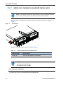
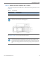
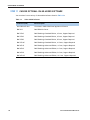
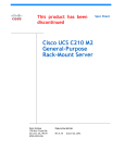
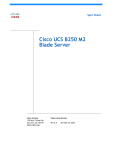
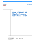
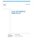
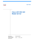
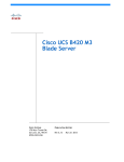
Spec Sheet
Cisco UCS B22 M3
Blade Server
CISCO SYSTEMS
170 WEST TASMAN DR.
SAN JOSE, CA, 95134
WWW.CISCO.COM
PUBLICATION HISTORY
REV A.2
JULY 5, 2012
CONTENTS
OVERVIEW . . . . . . . . . . . . . . . . . . . . . . . . . . . . . . . . . . . . . . . . . . . . . . . 3
DETAILED VIEWS . . . . . . . . . . . . . . . . . . . . . . . . . . . . . . . . . . . . . . . . . . . 4
Blade Server Front View . . . . . . . . . . . . . . . . . . . . . . . . . . . . . . . . . . . . . . . . . . . . . . .4
BASE SERVER STANDARD CAPABILITIES and FEATURES . . . . . . . . . . . . . . . . . 5
CONFIGURING the SERVER . . . . . . . . . . . . . . . . . . . . . . . . . . . . . . . . . . . . 7
STEP
STEP
STEP
STEP
STEP
STEP
STEP
STEP
STEP
STEP
STEP
STEP
ORDER
1 VERIFY SERVER SKU . . . . . . . . . . . . . . . . . . . . . . . . . . . . . . . . . . . . . . . . . . . . 8
2 CHOOSE CPU(S) . . . . . . . . . . . . . . . . . . . . . . . . . . . . . . . . . . . . . . . . . . . . . . 9
3 CHOOSE MEMORY . . . . . . . . . . . . . . . . . . . . . . . . . . . . . . . . . . . . . . . . . . . . 11
4 CHOOSE HARD DISK DRIVES or SOLID STATE DRIVES (OPTIONAL) . . . . . . . . . . . . . . 15
5 CHOOSE MODULAR LOM and/or PCIe MEZZANINE CARDS . . . . . . . . . . . . . . . . . . . 17
6 ORDER A TRUSTED PLATFORM MODULE . . . . . . . . . . . . . . . . . . . . . . . . . . . . . . 20
7 ORDER CISCO FLEXIBLE FLASH SECURE DIGITAL CARDS . . . . . . . . . . . . . . . . . . . . 21
8 ORDER OPTIONAL INTERNAL USB 2.0 DRIVE . . . . . . . . . . . . . . . . . . . . . . . . . . . 22
9 CHOOSE OPERATING SYSTEM . . . . . . . . . . . . . . . . . . . . . . . . . . . . . . . . . . . . . 23
10 CHOOSE OPERATING SYSTEM MEDIA KIT . . . . . . . . . . . . . . . . . . . . . . . . . . . . . 26
11 CHOOSE OPTIONAL VALUE-ADDED SOFTWARE . . . . . . . . . . . . . . . . . . . . . . . . . 27
12 CHOOSE SERVICE and SUPPORT LEVEL . . . . . . . . . . . . . . . . . . . . . . . . . . . . . . 28
OPTIONAL KVM LOCAL I/O CABLE* . . . . . . . . . . . . . . . . . . . . . . . . . . . . . . . . . . . 32
SUPPLEMENTAL MATERIAL . . . . . . . . . . . . . . . . . . . . . . . . . . . . . . . . . . . 33
System Board . . . . . . . . . . . . . . . . . . . . . . . . . . . . . . . . . . . . . . . . . . . . . . . . . . . . . 33
DIMM and CPU Layout . . . . . . . . . . . . . . . . . . . . . . . . . . . . . . . . . . . . . . . . . . . . . . . . 34
System Speed as a Function of DIMMs Per Channel (for a 3 DIMM Per Channel System) . 35
Network Connectivity . . . . . . . . . . . . . . . . . . . . . . . . . . . . . . . . . . . . . . . . . . . . . . . . 36
Modular LOM Card . . . . . . . . . . . . . . . . . . . . . . . . . . . . . . . . . . . . . . . . . . . . . . 37
Mezzanine Cards . . . . . . . . . . . . . . . . . . . . . . . . . . . . . . . . . . . . . . . . . . . . . . . 38
Connectivity using the Cisco UCS 2208XP Fabric Extender . . . . . . . . . . . . . . . . . . . . 39
Connectivity using the Cisco UCS 2204XP Fabric Extender . . . . . . . . . . . . . . . . . . . . 42
Connectivity using the Cisco UCS 2104XP Fabric Extender . . . . . . . . . . . . . . . . . . . . 45
TECHNICAL SPECIFICATIONS . . . . . . . . . . . . . . . . . . . . . . . . . . . . . . . . . . 46
Dimensions and Weight . . . . . . . . . . . . . . . . . . . . . . . . . . . . . . . . . . . . . . . . . . . . . . . 46
Power Specifications . . . . . . . . . . . . . . . . . . . . . . . . . . . . . . . . . . . . . . . . . . . . . . . . 46
Cisco UCS B22 M3 Blade Server
2
OVERVIEW
OVERVIEW
The Cisco® UCS B22 M3 Blade Server delivers a balanced price/performance feature set to address quick
deployment of scalable IT infrastructure and Web 2.0 applications. The Cisco UCS B22 M3 harnesses the
power of the latest Intel® Xeon® processor E5-2400 product family with expandability to 192 GB of RAM
(using 16 GB DIMMs), 2 hot-plug drives, and 2 PCIe mezzanine slots for up to 80 Gbps throughput.
Figure 1
Cisco UCS B22 M3 Blade Server
Cisco UCS B22 M3 Blade Server
2
DETAILED VIEWS
DETAILED VIEWS
Blade Server Front View
Figure 2 is a detailed front view of the Cisco UCS B22 M3 Blade Server.
Figure 2
Blade Server Front View
4
5
1
2
3
6
7
8
9
1
Asset pull handle
(a blank asset tag is provided on which
you can add your own label or sticker or
you can use a marker to write your asset
information on the tag)
7
Network link status LED
2
Blade ejector handle
8
Blade health LED
3
Ejector captive screw
9
Console connector1
4
Drive bay 1
10
Reset button access
5
Drive bay 2
11
Beaconing LED and button
6
Power button and LED
-
-
10
11
332661
UCS B22 M3
Notes
1. For information about the KVM local I/O cable that plugs into the console connector (a cable is included with
every Cisco UCS 5100 Series blade server chassis accessory kit), see ORDER OPTIONAL KVM LOCAL I/O CABLE*
on page 30.
3
Cisco UCS B22 M3 Blade Server
BASE SERVER STANDARD CAPABILITIES and FEATURES
BASE SERVER STANDARD CAPABILITIES and FEATURES
Table 1 lists the capabilities and features of the base server. Details about how to configure the server for
a particular feature or capability (for example, number of processors, disk drives, or amount of memory)
are provided in CONFIGURING the SERVER on page 6.
Table 1 Capabilities and Features
Capability/Feature
Description
Chassis
The UCS B22 M3 Blade Server mounts in a Cisco UCS 5100 series blade server
chassis
CPU
One or two Intel® E5-2400 series processor family CPUs
Chipset
Intel® C600 series chipset
Memory
12 total slots for registered ECC DIMMs for up to 192 GB total memory
capacity (using 16 GB DIMMs)
I/O
Mezzanine cards:
■
First connector for Cisco’s modular LAN on motherboard (mLOM), which
provides Ethernet and Fibre Channel over Ethernet (FCoE)
■
Second connector for various types of Cisco or third-party network
adapter cards
NOTE: The second connector is supported only for 2-CPU system
configurations.
Storage controller
LSI Logic SAS 2002 integrated controller
■
6 Gbs SAS/SATA support
■
RAID 0 and 1
NOTE: The integrated RAID controller does not implement a write
cache. However, servers that implement two HDDs and RAID
controllers with cache lack the ability to match the performance
of RAID’ed SSDs without cache.
Internal storage devices
Up to two optional, front-accessible, hot-swappable 2.5-inch small form
factor (SFF) SAS or SATA solid-state disks (SSDs) or hard disk drives (HDDs).
An internal USB 2.0 port is also supported. A 4 GB USB 2.0 device is available
from Cisco.
Cisco UCS B22 M3 Blade Server
4
BASE SERVER STANDARD CAPABILITIES and FEATURES
Table 1 Capabilities and Features (continued)
Capability/Feature
Video
Description
The Emulex Pilot 3 Integrated Baseboard Management Controller provides
video:
■
Matrox G200e video controller
■
Integrated 2D graphics core with hardware acceleration
■
Interfaces
Supports all display resolutions up to 1920 x 1200 x 16 bpp resolution at
60 Hz
■
24-bit color depth for all resolutions less than 1600x1200
■
Up to 256 MB video memory
■
Front panel
• One console connector (see ORDER OPTIONAL KVM LOCAL I/O
CABLE* on page 30)
Power subsystem
Integrated in the Cisco UCS 5100 series blade server chassis
Fans
Integrated in the Cisco UCS 5100 series blade server chassis
Integrated management
processor
The built-in Cisco Integrated Management Controller (CIMC) GUI or CLI
interface enables you to monitor the server inventory, health, and system
event logs.
5
Cisco UCS B22 M3 Blade Server
CONFIGURING the SERVER
CONFIGURING the SERVER
Follow these steps to configure the Cisco UCS B22 M3 Blade Server:
■
STEP 1 VERIFY SERVER SKU, page 7
■
STEP 2 CHOOSE CPU(S), page 8
■
STEP 3 CHOOSE MEMORY, page 10
■
STEP 4 CHOOSE HARD DISK DRIVES or SOLID STATE DRIVES (OPTIONAL), page 13
■
STEP 5 CHOOSE MODULAR LOM and/or PCIe MEZZANINE CARDS, page 15
■
STEP 6 ORDER A TRUSTED PLATFORM MODULE, page 18
■
STEP 7 ORDER CISCO FLEXIBLE FLASH SECURE DIGITAL CARDS, page 19
■
STEP 8 ORDER OPTIONAL INTERNAL USB 2.0 DRIVE, page 20
■
STEP 9 CHOOSE OPERATING SYSTEM, page 21
■
STEP 10 CHOOSE OPERATING SYSTEM MEDIA KIT, page 24
■
STEP 11 CHOOSE OPTIONAL VALUE-ADDED SOFTWARE, page 25
■
STEP 12 CHOOSE SERVICE and SUPPORT LEVEL, page 26
Cisco UCS B22 M3 Blade Server
6
CONFIGURING the SERVER
STEP 1
VERIFY SERVER SKU
Verify the product ID (PID) of the server as shown in Table 2.
Table 2 PID of the Base UCS B22 M3 Blade Server
Product ID (PID)
Description
UCSB-B22-M3
UCS B22 M3 Blade Server without CPU, memory, HDD, or mLOM/mezzanine cards
The base Cisco UCS B22 M3 blade server does not include the following components. They are to
be selected during product ordering:
■
CPU(s)
■
Memory
■
Disk drives
■
VIC 1240 modular LAN-on-Motherboard (mLOM) card
■
Mezzanine card
NOTE: Use the steps on the following pages to order the UCS B22 M3
server with the configurable components that you want configured.
7
Cisco UCS B22 M3 Blade Server
CONFIGURING the SERVER
STEP 2
CHOOSE CPU(S)
The standard CPU features are:
■
Intel Xeon processor E5-2400 series family CPUs
■
Intel C600 series chipset
■
Cache sizes of 10, 15, or 20 MB
Select CPUs
The supported Intel Xeon E5-2400 series family CPUs on the UCS B22 M3 are listed in Table 3.
Table 3 Supported Intel CPUs: E5-2400 Series Processor Family CPUs
Product ID (PID)
Intel
Number
Clock
Freq
(GHz)
UCS-CPU-E5-2470
E5-2470
2.30
95
20
UCS-CPU-E5-2450
E5-2450
2.10
95
UCS-CPU-E5-2440
E5-2440
2.40
UCS-CPU-E5-2430L
E5-2430L
UCS-CPU-E5-2420
UCS-CPU-E5-2403
QPI
Highest DDR3 DIMM
Clock Support (MHz)1
8
8 GT/s
1600
20
8
8 GT/s
1600
95
15
6
7.2 GT/s
1333
2.00
60
15
6
6.4 GT/s
1333
E5-2420
1.90
95
15
6
7.2 GT/s
1333
E5-2403
1.80
80
10
4
6.4 GT/s
1066
Power Cache Size
Cores
(W)
(MB)
Notes
1. If higher or lower speed DIMMs are selected than what is shown in the table for a given CPU, the DIMMs will be
clocked at the lowest common denominator of CPU clock and DIMM clock. For example:
Selecting lower-speed DIMMs: If you use an E4-2470 CPU (which can support up to 1600-MHz DIMMs) with 1333-MHz
DIMMs, the DIMMs will be clocked at the lower speed of 1333 MHz.
Selecting higher-speed DIMMs: If you use 1600-MHz DIMMs with an E5-2420 CPU (which can support up to 1333-MHz
DIMMs), the DIMMS will be clocked at the lower speed of 1333 MHz.
Cisco UCS B22 M3 Blade Server
8
CONFIGURING the SERVER
Supported Configurations
(1) 1-CPU Configuration
■
Choose one CPU from any one of the rows of Table 3 on page 8.
(2) Two-CPU Configuration
■
Choose two identical CPUs from any one of the rows of Table 3 on page 8.
Caveats
9
■
The VIC 1240 card is supported for 1- or 2-CPU configurations.
■
Mezzanine cards are supported only for 2-CPU configurations.
Cisco UCS B22 M3 Blade Server
CONFIGURING the SERVER
STEP 3
CHOOSE MEMORY
The standard memory features are:
■
Figure 3
DIMMs
—
Clock speed: 1600 MHz
—
Ranks per DIMM: 1 or 2
—
Operational voltage: dual (1.5 or 1.35 V)
—
Registered
■
DDR3 ECC registered DIMMs (RDIMMs)
■
Memory is organized with three memory channels per CPU, with up to two DIMMs per
channel (DPC), as shown in Figure 3. Maximum memory capacity is 192 GB (with 16 GB
DIMMs).
UCS B22 M3 Memory Organization
Cisco UCS B22 M3 Blade Server
10
CONFIGURING the SERVER
Choose DIMMs and Memory Mirroring
Select the memory configuration and whether or not you want the memory mirroring option.
The supported memory DIMMs and the mirroring option are listed in Table 4.
NOTE: When memory mirroring is enabled, the memory subsystem simultaneously
writes identical data to two adjacent channels. If a memory read from one of the
channels returns incorrect data due to an uncorrectable memory error, the system
automatically retrieves the data from the other channel. A transient or soft error in
one channel does not affect the mirrored data, and operation continues unless there
is a simultaneous error in exactly the same location on a DIMM and its mirrored
DIMM. Memory mirroring reduces the amount of memory available to the operating
system by 50% because only one of the two populated channels provides data.
The supported memory DIMMs in the UCS B22 M3 are listed in Table 4.
Table 4 Supported DDR3 DIMMs and Memory Mirroring Option
Product ID (PID)
Ranks
/DIMM
PID Description
Voltage
UCS-MR-1X162RY-A
16GB DDR3-1600-MHz RDIMM/PC3-12800/2R/x4/1.35v/35nm
1.35/1.5 V 2
UCS-MR-1X082RY-A
8GB DDR3-1600-MHz RDIMM/PC3-12800/2R/x4/1.35v/35nm
1.35/1.5 V 2
UCS-MR-1X041RY-A
4GB DDR3-1600-MHz RDIMM/PC3-12800/1R/x4/1.35v/35nm
1.35/1.5 V 1
DIMM Options
Memory Mirroring Option
N01-MMIRROR
11
Memory mirroring option
Cisco UCS B22 M3 Blade Server
CONFIGURING the SERVER
Supported Configurations
(1) Without memory mirroring:
■
Select from 1 to 6 DIMMs per CPU (note that there are 6 DIMM slots per CPU)
(2) With memory mirroring:
■
Select 2 or 4 DIMMs per CPU. The DIMMs must be identical across channels for the same
banks.The DIMMs will be placed by the factory as shown in Table 5:
Table 5 DIMM Placement With Memory Mirroring
Number of
DIMMs per
CPU
DIMM Placement in Channels (with memory mirroring implemented).
Note that Channels B and F are not used for memory mirroring
CPU 1
CPU 2
2
1 DIMM in Channel C (C0),
1 DIMM in Channel D (D0)
1 DIMM in Channel G (G0),
1 DIMM in Channel H (H0)
4
2 DIMMs in Channel C (C0, C1),
2 DIMMs in Channel D (D0, D1)
2 DIMMs in Channel G (G0, G1),
2 DIMMs in Channel H (H0. H1)
■
Select the memory mirroring option (N01-MMIRROR) as shown in Table 4 on page 11.
NOTE: System performance is optimized when the DIMM type and quantity are equal
for both CPUs, and when all channels are filled equally across the CPUs in the server.
Caveats
■
For 2-CPU configurations, DIMMs must be even across the server (2, 4, 6 up to 12). For
example, you can select four 8 GB DIMMs and six 16 GB DIMMs.
■
Memory mirroring reduces the amount of available memory by 50% (quantity of DIMMs must
be even for mirroring).
■
By default, all DIMMs run at 1.35 V, which yields 1333-MHz memory speeds. To run the
memory DIMMS at 1600 MHz, you need to go into the BIOS or set the policy with UCSM
(service profile) to run in Performance Mode. This forces the DIMMs to operate at 1.5 V and
yields 1600-MHz speeds provided:
—
The DIMMs are 1600-MHz devices
—
The CPUs chosen support 1600-MHz operation
For more information regarding memory, see DIMM and CPU Layout on page 32 and
DIMM Population on page 34.
Cisco UCS B22 M3 Blade Server
12
CONFIGURING the SERVER
STEP 4
CHOOSE HARD DISK DRIVES or SOLID STATE DRIVES (OPTIONAL)
The UCS B22 M3 can be ordered with or without drives. The standard disk drive features are:
■
2.5-inch small form factor
■
Hot-pluggable sled mounted
NOTE: The UCS B22 M3 blade server meets the external storage target and switch
certifications as described in the following link:
http://www.cisco.com/en/US/docs/switches/datacenter/mds9000/interoperability
/matrix/Matrix8.html#wp323852
Choose Drives
The supported drives in the UCS B22 M3 are listed in Table 6.
Table 6 Supported Hot-Pluggable Sled-Mounted HDDs and SSDs
PID Description
Drive
Type
Capacity
A03-D600GA2
600 GB 6 Gb SAS 10K RPM SFF HDD
SAS
600 GB
UCS-HDD300GI2F105
300 GB 6 Gb SAS 15K RPM SFF HDD
SAS
300 GB
A03-D300GA2
300 GB 6 Gb SAS 10K RPM SFF HDD
SAS
300 GB
A03-D146GC2
146 GB 6 Gb SAS 15K RPM SFF HDD
SAS
146 GB
100 GB Std Height 15mm SATA SSD
SATA
100 GB
Product ID (PID)
HDDs
SSDs
UCS-SD100G0KA2-E
NOTE: The integrated LSI 2002 MegaRAID controller supports hard disk drives (HDDs)
or solid state drives (SSDs). Write cache is not implemented. SSDs are recommended
for applications requiring high-speed local storage, which is an order of magnitude
faster than HDDs.
Supported Configurations
(1) 1-Drive System
■
13
Select one of the drives listed in Table 6.
Cisco UCS B22 M3 Blade Server
CONFIGURING the SERVER
(1) 2-Drive System
■
Select two identical drives from Table 6. There is no support for mixing of drive types or
capacities.
Caveats
■
If you select two drives, they must be identical in type and capacity.
Cisco UCS B22 M3 Blade Server
14
CONFIGURING the SERVER
STEP 5
CHOOSE MODULAR LOM and/or PCIe MEZZANINE CARDS
The card offerings are:
■
Virtual Interface Cards (VICs)
Cisco-developed Virtual Interface Cards (VICs) provide the flexibility to create multiple NIC and
HBA devices. The VICs also support adapter Fabric Extender and Virtual Machine Fabric Extender
(FEX) technologies.
■
Converged Network Adapters (CNAs)
Industry-standard Converged Network Adapters (CNAs) consolidate Ethernet and Storage (FC)
traffic on the Unified Fabric by supporting FCoE.
■
Network Interface Cards (NICs)
Industry-standard Network Interface Cards (NICs) provide Ethernet connectivity to the server.
NOTE: There are two connectors on the server to accommodate mezzanine cards.
One is a connector that accommodates Cisco and third-party PCIe CNA and NIC cards
and one is a dedicated modular LAN-on-motherboard (mLOM) connector for the VIC
1240 card only. Table 7 shows which cards plug into each of the two connectors.
Only the VIC 1240 card plugs into the mLOM connector. All other cards plug into the
PCIe mezzanine connector.
NOTE: You must have a 2-CPU system to support cards that plug into the mezzanine
connector. The VIC 1240 mLOM card is supported on both 1- and 2-CPU configured
systems.
Choose a Mezzanine Option Card
The supported mezzanine cards in the UCS B22 M3 are listed in Table 7.
Table 7 Supported Mezzanine Cards
Product ID (PID)
PID Description
Connector
Virtual Interface Cards (VICs)
UCSB-MLOM-40G-01
Cisco UCS VIC 1240 modular LOM for M3 blade servers. Plugs into
the dedicated mLOM connector only. It is the only card that can be
plugged into the mLOM connector.
mLOM
UCS-VIC-M82-8P
Cisco UCS VIC 1280 dual 40 Gb capable Virtual Interface Card
PCIe
15
Cisco UCS B22 M3 Blade Server
CONFIGURING the SERVER
Supported Configurations
(1) Select One modular LOM and/or One PCIe Mezzanine Cards
Select one or two cards as desired in accordance with Table 8.
Table 8 Modular LOM and Mezzanine Card Options
Fabric
Extender
Compatibility
Card in
modular LOM
Connector
Card in Mezzanine Connector
(PCIe)
Ports
Reference
2208XP (PIDs UCS-IOM-2208XP, UCS-IOM2208-16FET)
2208XP
VIC 1240
None
4 x 10 Gb
Figure 11 on page 38
2208XP
VIC 1240
VIC 1280
8 x 10 Gb
Figure 12 on page 39
2208XP
VIC 1240
3rd-party Mezzanine Card1
6 x 10 Gb
Figure 13 on page 39
2208XP
None
3rd-party Mezzanine Card1
2 x 10 Gb
Figure 14 on page 40
2204XP (PIDs UCS-IOM-2204XP, UCS-IOM2204-8FET)
2204XP
VIC 1240
None
2 x 10 Gb
Figure 15 on page 41
2204XP
VIC 1240
VIC 1280
4 x 10 Gb
Figure 16 on page 42
2204XP
VIC 1240
3rd-party Mezzanine Card1
4 x 10 Gb
Figure 17 on page 42
2204XP
None
3rd-party Mezzanine Card1
2 x 10 Gb
Figure 18 on page 43
None2
2 x 10 Gb
Figure 19 on page 44
2104XP (PID N20-I6584)
2104XP
VIC 1240
Notes
1. To be supported in the future
2. The 2104XP fabric extender is not compatible with any I/O card installed in the mezzanine connector.
Cisco UCS B22 M3 Blade Server
16
CONFIGURING the SERVER
Also see Network Connectivity on page 35 for more information.
To help ensure that your operating system is compatible with the cards you have selected,
please check the Hardware Compatibility List at this URL:
http://www.cisco.com/en/US/products/ps10477/prod_technical_reference_list.html
Caveats
17
■
If a VIC 1240 modular LOM card is not installed, you must choose a network card to be
installed in the mezzanine card slot (see also Network Connectivity on page 35)
■
The mezzanine cards are not supported for 1-CPU configurations. You must have two CPUs
installed before you can install and use mezzanine cards.
Cisco UCS B22 M3 Blade Server
CONFIGURING the SERVER
STEP 6
ORDER A TRUSTED PLATFORM MODULE
Trusted Platform Module (TPM) is a computer chip (microcontroller) that can securely store
artifacts used to authenticate the platform (server). These artifacts can include passwords,
certificates, or encryption keys. A TPM can also be used to store platform measurements that
help ensure that the platform remains trustworthy. Authentication (ensuring that the platform
can prove that it is what it claims to be) and attestation (a process helping to prove that a
platform is trustworthy and has not been breached) are necessary steps to ensure safer
computing in all environments.
The TPM ordering information is listed in Table 9.
Table 9
Trusted Platform Module
Product ID (PID)
PID Description
UCSX-TPM1-001
Trusted Platform Module for UCS
Cisco UCS B22 M3 Blade Server
18
CONFIGURING the SERVER
STEP 7
ORDER CISCO FLEXIBLE FLASH SECURE DIGITAL CARDS
NOTE: Cisco Flexible Flash secure digital cards are currently orderable; however,
they will be enabled only with future firmware and software updates.
Dual SDHC flash card sockets are provided on the front left side of the server as shown in
Figure 4.
SD Locations
332219
Figure 4
The SDHC card ordering information is listed in Table 10.
Table 10
Cisco Flexible Flash Secure Digital Cards
Product ID (PID)
PID Description
UCS-SD-16G
16 GB SD Card module for UCS Servers
NOTE: The SD card transfer rates are:
■
Sequential reads: 23 MB/s
■
Sequential writes: 20 MB/s
Future Supported Configurations
(1) Select one or two Cisco Flexible Flash secure digital card
19
Cisco UCS B22 M3 Blade Server
CONFIGURING the SERVER
STEP 8
ORDER OPTIONAL INTERNAL USB 2.0 DRIVE
You may order one optional internal USB 2.0 drive. The USB drive ordering information is listed
in Table 11.
Table 11
USB 2.0 Drive
Product ID (PID)
PID Description
UCS-USBFLSH-S-4GB
4GB Flash USB Drive (shorter length) for all servers except C260
NOTE: A clearance of 0.950 inches (24.1 mm) is required for the USB device to be
inserted and removed (see the following figure).
See Figure 6 on page 31 for the location of the USB connector.
NOTE: When the Cisco 4GB USB key is purchased with a server, it is pre-installed
into the internal USB port and held firmly in place with a clip to protect it from
shock and vibration during shipment and transportation. This clip also prevents the
USB key from undergoing shock and vibration during ongoing customer operational
use.
Cisco UCS B22 M3 Blade Server
20
CONFIGURING the SERVER
STEP 9
CHOOSE OPERATING SYSTEM
Several operating systems are available from which to choose. Choose one of the operating
systems listed in Table 12.
Table 12
Operating Systems
PID Description
Product ID (PID)
SUSE Linux Enterprise Server
SLES-1A
SLES/1yr subscription/svcs required/0 media
SLES-3A
SLES/3yr subscription/svcs required/0 media
Red Hat Enterprise Linux
RHEL-2S-1G-1A
RHEL/2 Socket/1 Guest/1Yr Svcs Required
RHEL-2S-1G-3A
RHEL/2 Socket/1 Guest/3Yr Svcs Required
RHEL-2S-4G-1A
RHEL/2 Socket/4 Guest/1Yr Svcs Required
RHEL-2S-4G-3A
RHEL/2 Socket/4 Guest/3Yr Svcs Required
RHEL-2S-UG-1A
RHEL/2 Socket/U Guest/1Yr Svcs Required
RHEL-2S-UG-3A
RHEL/2 Socket/U Guest/3Yr Svcs Required
RHEL-2S-1G-1A-RS
RHEL/2 Socket/1 Guest/1Yr Subscription/Redhat Svcs Included
RHEL-2S-1G-3A-RS
RHEL/2 Socket/1 Guest/3Yr Subscription/Redhat Svcs Included
RHEL-2S-4G-1A-RS
RHEL/2 Socket/4 Guest/1Yr Subscription/Redhat Svcs Included
RHEL-2S-4G-3A-RS
RHEL/2 Socket/4 Guest/3Yr Subscription/Redhat Svcs Included
RHEL-2S-UG-1A-RS
RHEL/2 Socket/U Guest/1Yr Subscription/Redhat Svcs Included
RHEL-2S-UG-3A-RS
RHEL/2 Socket/U Guest/3Yr Subscription/Redhat Svcs Included
RHEL Add-Ons
21
RHEL-HA-2S-1A
RHEL Option/High-Availability/2 Socket/1Yr Svcs Required
RHEL-RS-2S-1A
RHEL Option/Resilient w/Ha /2 Socket/1 Yr Svcs Required
RHEL-SFS-2S-1A
RHEL Option/Scalable File System/2 Socket/1 Yr Svcs Required
RHEL-HA-2S-3A
RHEL Option/High-Availability/2 Socket/3Yr Svcs Required
RHEL-RS-2S-3A
RHEL Option/Resilient Storage w/ HA /2 Socket/3 Yr Svcs Reqd
RHEL-SFS-2S-3A
RHEL Option/Scalable File System/2 Socket/3 Yr Svcs Required
RHEL-HA-2S-1A-RS
RHEL Option/High-Availability/2 Socket/1Yr Redhat Svcs Incld
RHEL-RS-2S-1A-RS
RHEL Option/Resilient Storage/2 Socket/1 Yr Redhat Svcs Incld
Cisco UCS B22 M3 Blade Server
CONFIGURING the SERVER
Table 12
Operating Systems (continued)
PID Description
Product ID (PID)
RHEL-SFS-2S-1A-RS
RHEL Option/Scalable File Sys/2 Socket/1 Yr Redhat Svcs Incl
RHEL-HA-2S-3A-RS
RHEL Option/High-Availability/2 Socket/3Yr Redhat Svcs Incld
RHEL-RS-2S-3A-RS
RHEL Option/Resilient Storage/2 Socket/3 Yr Redhat Svcs Incl
RHEL-SFS-2S-3A-RS
RHEL Option/Scalable File Sys/2 Socket/3 Yr Redhat Svcs Incl
Windows Server
MSWS-08-STHV
Windows Svr 2008 ST media (1-4CPU, 5CAL)
MSWS-08-ENHV
Windows Svr 2008 EN media (1-8CPU, 25CAL)
MSWS-08R2-STHV
Windows Svr 2008 ST media R2 ST (1-4CPU, 5CAL)
MSWS-08R2-ENHV
Windows Svr 2008 EN media R2 EN (1-8CPU, 25CAL)
MSWS-08R2-DCHV2S Windows Svr 2008 R2-2 CPU-Data Center
MSWS-08R2-DCHV4S Windows Svr 2008 R2-4 CPU-Data Center
VMware Server
VMW-VS5-STD-1A
VMware vSphere 5 Standard for 1 Processor, 1 Year, Support Required
VMW-VS5-STD-2A
VMware vSphere 5 Standard for 1 Processor, 2 Year, Support Required
VMW-VS5-STD-3A
VMware vSphere 5 Standard for 1 Processor, 3 Year, Support Required
VMW-VS5-STD-4A
VMware vSphere 5 Standard for 1 Processor, 4 Year, Support Required
VMW-VS5-STD-5A
VMware vSphere 5 Standard for 1 Processor, 5 Year, Support Required
VMW-VS5-ENT-1A
VMware vSphere 5 Enterprise for 1 Processor, 1 Year Support Required
VMW-VS5-ENT-2A
VMware vSphere 5 Enterprise for 1 CPU, 2 Yr Support Required
VMW-VS5-ENT-3A
VMware vSphere 5 Enterprise for 1 CPU, 3 Yr Support Required
VMW-VS5-ENT-4A
VMware vSphere 5 Enterprise for 1 Processor, 4 Year Support Required
VMW-VS5-ENT-5A
VMware vSphere 5 Enterprise for 1 CPU, 5 Yr Support Required
VMW-VS5-ENTP-1A
VMware vSphere 5 Enterprise Plus for 1 Processor, 1 Year, Support Required
VMW-VS5-ENTP-2A
VMware vSphere 5 Enterprise Plus for 1 CPU, 2 Yr Support Required
VMW-VS5-ENTP-3A
VMware vSphere 5 Enterprise Plus for 1 Processor, 3 Year, Support Required
VMW-VS5-ENTP-4A
VMware vSphere 5 Enterprise Plus for 1 Processor, 4 Year Support Required
VMW-VS5-ENTP-5A
VMware vSphere 5 Enterprise Plus for 1 Processor, 5 Year, Support Required
VMW-VC5-ST-1A
VMware vCenter 5 Standard for 1 Processor, 1 Year, Support Required
VMW-VC5-ST-2A
VMware vCenter 5 Standard for 1 Processor, 2 Year, Support Required
Cisco UCS B22 M3 Blade Server
22
CONFIGURING the SERVER
Table 12
Operating Systems (continued)
PID Description
Product ID (PID)
VMW-VC5-ST-3A
VMware vCenter 5 Standard for 1 Processor, 3 Year, Support Required
VMW-VC5-ST-4A
VMware vCenter 5 Standard for 1 Processor, 4 Year, Support Required
VMW-VC5-ST-5A
VMware vCenter 5 Standard for 1 Processor, 5 Year, Support Required
NOTE: For additional information, see OS/hypervisor support matrix at the
following link:
http://www.cisco.com/en/US/products/ps10477/prod_technical_reference_list.h
tml
23
Cisco UCS B22 M3 Blade Server
CONFIGURING the SERVER
STEP 10 CHOOSE OPERATING SYSTEM MEDIA KIT
Choose the optional operating system media listed in Table 13.
Table 13
OS Media
Product ID (PID)
PID Description
RHEL-6
RHEL 6 Recovery Media Only (Multilingual)
SLES-11
SLES 11 media only (multilingual)
MSWS-08R2-STHV-RM
Windows Svr 2008 R2 ST (1-4CPU, 5CAL), Media
MSWS-08RS-ENHV-RM
Windows Svr 2008 R2 EN (1-8CPU, 25CAL), Media
MSWS-08R2-DCHV-RM
Windows Svr 2008 R2 DC (1-8CPU, 25CAL), Media
Cisco UCS B22 M3 Blade Server
24
CONFIGURING the SERVER
STEP 11 CHOOSE OPTIONAL VALUE-ADDED SOFTWARE
You can select from a variety of value-added software listed in Table 13.s
Table 14
25
Value Added Software
Product ID (PID)
PID Description
N1K-CSK9-UCS-404
Cisco Nexus 1000V VSM Virtual Appliance Software
BMC-012
BMC BPPM Per Server
BMC-SE-4C
BMC BladeLogic Standard Edition, 4 Cores, Support Required
BMC-SE-6C
BMC BladeLogic Standard Edition, 6 Cores, Support Required
BMC-SE-8C
BMC BladeLogic Standard Edition, 8 Cores, Support Required
BMC-SE-10C
BMC BladeLogic Standard Edition, 10 Cores, Support Required
BMC-AE-4C
BMC BladeLogic Advanced Edition, 4 Cores, Support Required
BMC-AE-6C
BMC BladeLogic Advanced Edition, 6 Cores, Support Required
BMC-AE-8C
BMC BladeLogic Advanced Edition, 8 Cores, Support Required
BMC-AE-10C
BMC BladeLogic Advanced Edition, 10 Cores, Support Required
Cisco UCS B22 M3 Blade Server
CONFIGURING the SERVER
STEP 12 CHOOSE SERVICE and SUPPORT LEVEL
A variety of service options are available, as described in this section.
Unified Computing Warranty, No Contract
If you have noncritical implementations and choose to have no service contract, the following
coverage is supplied:
■
Three-year parts coverage.
■
Next business day (NBD) parts replacement eight hours a day, five days a week.
■
90-day software warranty on media.
■
Downloads of BIOS, drivers, and firmware updates.
■
UCSM updates for systems with Unified Computing System Manager. These updates include
minor enhancements and bug fixes that are designed to maintain the compliance of UCSM
with published specifications, release notes, and industry standards.
Unified Computing Support Service
For support of the entire Unified Computing System, Cisco offers the Cisco Unified Computing
Support Service. This service provides expert software and hardware support to help sustain
performance and high availability of the unified computing environment. Access to Cisco
Technical Assistance Center (TAC) is provided around the clock, from anywhere in the world.
For UCS blade servers, there is Smart Call Home, which provides proactive, embedded
diagnostics and real-time alerts. For systems that include Unified Computing System Manager,
the support service includes downloads of UCSM upgrades. The Unified Computing Support
Service includes flexible hardware replacement options, including replacement in as little as
two hours. There is also access to Cisco's extensive online technical resources to help maintain
optimal efficiency and uptime of the unified computing environment. You can choose a desired
service listed in Table 15.
Table 15
UCS Computing Support Service
Product ID (PID)
On Site?
Description
CON-UCS1-B22-M3
No
UC Support 8X5XNBD
CON-UCS2-B22-M3
No
UC Support 8X5X4
CON-UCS3-B22-M3
No
UC Support 24x7x4
CON-UCS4-B22-M3
No
UC Support 24x7x2
CON-UCS5-B22-M3
Yes
UC Support 8X5XNBD
CON-UCS6-B22-M3
Yes
UC Support 8X5X4
CON-UCS7-B22-M3
Yes
UC Support 24x7x4
CON-UCS8-B22-M3
Yes
UC Support 24x7x2
Unified Computing Warranty Plus Service
Cisco UCS B22 M3 Blade Server
26
CONFIGURING the SERVER
For faster parts replacement than is provided with the standard Cisco Unified Computing System
warranty, Cisco offers the Cisco Unified Computing Warranty Plus Service. You can choose from
several levels of advanced parts replacement coverage, including onsite parts replacement in as
little as two hours. Warranty Plus provides remote access any time to Cisco support professionals
who can determine if a return materials authorization (RMA) is required. You can choose a
service listed in Table 16.
Table 16
UCS Computing Warranty Plus Service
Product ID (PID)
On Site?
Description
CON-UCW2-B22-M3
No
UC Warranty Plus 8x5x4
CON-UCW3-B22-M3
No
UC Warranty Plus 24x7x4
CON-UCW4-B22-M3
No
UC Warranty Plus 24x7x2
CON-UCW5-B22-M3
Yes
UC Warranty Plus 8X5XNBD
CON-UCW6-B22-M3
Yes
UC Warranty Plus 8X5X4
CON-UCW7-B22-M3
Yes
UC Warranty Plus 24x7x4
CON-UCW8-B22-M3
Yes
UC Warranty Plus 24x7x2
Unified Computing Drive Retention Service
With the Cisco Unified Computing Drive Retention (UCDR) service, you can obtain a new disk
drive in exchange for a faulty drive without returning the faulty drive. In exchange for a Cisco
replacement drive, you provide a signed Certificate of Destruction (CoD) confirming that the
drive has been removed from the system listed, is no longer in service, and has been destroyed.
Sophisticated data recovery techniques have made classified, proprietary, and confidential
information vulnerable, even on malfunctioning disk drives. The UCDR service enables you to
retain your drives and ensures that the sensitive data on those drives is not compromised,
thereby reducing the risk of any potential liabilities. This service also enables you to comply
with regulatory, local, and federal requirements.
If your company has a need to control confidential, classified, sensitive, or proprietary data, you
might want to consider one of the Drive Retention Services listed in Table 17.
NOTE: Cisco does not offer a certified drive destruction service as part of this
service.
27
Cisco UCS B22 M3 Blade Server
CONFIGURING the SERVER
Table 17 Drive Retention Service Options
Service Description
UCS Mission Critical
Support Service
With Drive
Retention
UCS Support
Service With Drive
Retention
UCS Warranty Plus
With Drive
Retention
Service
Program Name
Service
Level GSP
Service Level
Product ID (PID)
UC CRIT DR
UCMD7
24x7x4 Onsite
CON-UCMD7-B22-M3SFF
UCMD8
24x7x2 Onsite
CON-UCMD8-B22-M3SFF
UCSD1
8x5xNBD
CON-UCSD1-B22-M3SFF
UCSD2
8x5x4
CON-UCSD2-B22-M3SFF
UCSD3
24x7x4
CON-UCSD3-B22-M3SFF
UCSD4
24x7x2
CON-UCSD4-B22-M3SFF
UCSD5
8x5xNBD Onsite
CON-UCSD5-B22-M3SFF
UCSD6
8x5x4 Onsite
CON-UCSD6-B22-M3SFF
UCSD7
24x7x4 Onsite
CON-UCSD7-B22-M3SFF
UCSD8
24x7x2 Onsite
CON-UCSD8-B22-M3SFF
UCWD2
8x5x4
CON-UCWD2-B22-M3SFF
UCWD3
24x7x4
CON-UCWD3-B22-M3SFF
UCWD4
24x7x2
CON-UCWD4-B22-M3SFF
UCWD5
8x5xNBD Onsite
CON-UCWD5-B22-M3SFF
UCWD6
8x5x4 Onsite
CON-UCWD6-B22-M3SFF
UCWD7
24x7x4 Onsite
CON-UCWD7-B22-M3SFF
UCWD8
24x7x2 Onsite
CON-UCWD8-B22-M3SFF
UC SUPP DR
UC PLUS DR
Mission Critical Support Service
This service delivers personalized technical account management, expedited technical support,
and expert field support engineering for the Cisco Unified Computing System (UCS).
The Mission Critical Support Service provides a designated technical account manager (TAM) who
acts as a strategic resource to help ensure that the unified computing environment runs at peak
efficiency. If a problem arises that threatens business continuity, the TAM provides crisis
management leadership, and your IT staff receives expedited access to Cisco's Technical
Assistance Center (TAC).
Mission Critical Support Service is a layered service available for all Cisco data center products
already support by a UCS Support Service or SMARTnet service contract. For further information
Cisco UCS B22 M3 Blade Server
28
CONFIGURING the SERVER
about Cisco Mission Critical Support Service, please consult the Service Description that can be
found at the following link:
http://www.cisco.com/web/about/doing_business/legal/service_descriptions/index.html
or contact your Cisco account Manager.
For more service and support information, see the following URL:
http://www.cisco.com/en/US/services/ps2961/ps10312/ps10321/Cisco_UC_Warranty_Support_DS.pdf
For a complete listing of available services for Cisco Unified Computing System, see this URL:
http://www.cisco.com/en/US/products/ps10312/serv_group_home.html
29
Cisco UCS B22 M3 Blade Server
CONFIGURING the SERVER
ORDER OPTIONAL KVM LOCAL I/O CABLE*
The KVM local I/O cable ships with every UCS 5100 Series blade server chassis accessory kit. The KVM local
I/O cable provides a connection into the server, providing a DB9 serial connector, a VGA connector for a
monitor, and dual USB ports for a keyboard and mouse. With this cable, you can create a direct connection
to the operating system and the BIOS running on the server.
The KVM local I/O cable ordering information is listed in Table 18.
Table 18 KVM Local I/O Cable
Product ID (PID)
PID Description
N20-BKVM=
KVM local IO cable for UCS servers console port
Figure 5
KVM Local I/O Cable
1
Connector (to server front panel)
3
VGA connector (for a monitor)
2
DB-9 serial connector
4
Two-port USB connector (for a mouse and
keyboard)
NOTE: *The blade chassis ships with the KVM local I/O cable.
Cisco UCS B22 M3 Blade Server
30
SUPPLEMENTAL MATERIAL
SUPPLEMENTAL MATERIAL
System Board
A top view of the UCS B22 M3 system board is shown in Figure 6.
Figure 6
UCS B22 M3 System Board
1
2
3
4
5
6
7
8
9
10
F0
F1
G0
G1
H0
H1
CPU 1
CPU 2
D1
D0
C1
C0
332662
B1
B0
1
Drive bays
6
Diagnostic button
2
Internal USB connector1
7
CPU 2 DIMM slots
3
Battery
8
CPU 2 and heat sink
4
CPU 1 and heat sink
9
Modular LOM (shown installed)
5
CPU 1 DIMM slots
10
Mezzanine card connector (card not shown)
Notes
1. A USB device installed in this connector must have sufficient clearance to easily slide in and out. The Cisco USB
device clearance is 0.950 inches (24.1 mm), which is a sufficient amount of clearance.
31
Cisco UCS B22 M3 Blade Server
SUPPLEMENTAL MATERIAL
DIMM and CPU Layout
Memory is organized as shown in Figure 7.
Figure 7
UCS B22 M3 Memory Organization
Each CPU controls three memory channels, as follows:
■
■
CPU1: Channels B, C, and D
—
Bank 0 - B0, C0, and D0 (blue DIMM slots)
—
Bank 1 - B1, C1, and D1 (black DIMM slots)
CPU2: Channels F, G, and H
—
Bank 0 - F0, G0, and H0 (blue DIMM slots)
—
Bank 1 - F, G1, and H1 (black DIMM slots)
The DIMM and CPU physical layout is shown in Figure 8. The 6 DIMM slots at the left are controlled by CPU 1
and the 6 DIMM slots on the right are controlled by CPU 2.
Cisco UCS B22 M3 Blade Server
32
SUPPLEMENTAL MATERIAL
Figure 8
DIMM and CPU Layout
2
F0
F1
G0
G1
H0
H1
CPU 1
CPU 2
D1
D0
C1
C0
B1
B0
1
1
33
Channels B-D for CPU 1
2
Channels F-H for CPU 2
Cisco UCS B22 M3 Blade Server
SUPPLEMENTAL MATERIAL
DIMM Population
Recommended DIMM Populations
Table 19 shows the recommended DIMM slot populations.
Table 19 Recommended DIMM Population
DIMMs per
Channel
DIMMs in Each
Channel
1-CPU Memory Size
2-CPU Memory Size
DIMM Speed
8 GB
24
48
1600 MHz
16 GB
48
96
1600 MHz
4 GB + 4 GB
24
48
1600 MHz
8 GB + 8 GB
48
96
1600 MHz
16 GB + 16 GB
96
192
1600 MHz
4 GB + 8 GB
36
72
1600 MHz
4 GB + 16 GB
60 GB
120 GB
1600 MHz
8 GB + 16 GB
72 GB
144 GB
1600 MHz
1
2
If 4 GB DIMMs are mixed with 8 GB or 16 GB DIMMs, the DIMM slots are populated as shown in Table 20.
Table 20 4 GB DIMMs Mixed with 8 GB or 16 GB DIMMs
Total
Number
Memory
of CPUs
(GB)
CPU 1 DIMM Size (GB) Populated
B0
B1
C0
C1
D0
D1
F0
F1
G0
G1
H0
H1
none
none
none
none
none
none
none
none
none
12/20
4
24/40
4
4
8/16
8/16
none
none
none
none
none
none
none
none
4
4
4
4
none
none
none
none
none
none
none
none
16
4
4
4
4
none
none
none
none
none
none
none
none
32/48
4
4
4
4
8/16
8/16
none
none
none
none
none
none
28/36
4
4
4
4
4
8/16
none
none
none
none
none
none
24/40
4
none
none
none
4
8/16
none
none
none
none
20/28
48/80
1
2
8/16 none
CPU 2 DIMM Size (GB) Populated
8/16 none
4
4
8/16
8/16
none
none
4
4
8/16
8/16
none
none
40/56
4
4
4
8/16
none
none
4
4
4
8/16
none
none
32
4
4
4
4
none
none
4
4
4
4
none
none
64/96
4
4
4
4
8/16
8/16
4
4
4
4
8/16
8/16
56/72
4
4
4
4
4
8/16
4
4
4
4
4
8/16
Cisco UCS B22 M3 Blade Server
34
SUPPLEMENTAL MATERIAL
Network Connectivity
This section explains how the UCS B22 M3 server connects to Fabric Interconnects using the network cards
in the UCS B22 M3 blade server and the Fabric Extender modules in the UCS 5108 blade server chassis. The
UCS B22 M3 server plugs into the front of the UCS 5108 blade server chassis. The Fabric Extender modules
plug into the back of the UCS 5108 series blade server chassis. A midplane connects the UCS B22 M3 blade
server to the Fabric Extenders. Figure 9 shows an example configuration where two 2 x 10G KR ports are
routed from the VIC 1240 modular LAN-on-motherboard (LOM) card to the Fabric Extender modules, and
two 2 x 10G KR ports are routed from the mezzanine card to the Fabric Extender modules.
Figure 9
UCS B22 M3 Connections to the Fabric Extenders
The server accommodates two types of network cards. One is the Cisco VIC 1240 modular
LAN-on-motherboard (mLOM) card. The other type is a mezzanine card. The VIC 1240 is the only card that
can be used in the modular LOM connector. All other types of cards plug into the mezzanine PCIe connector.
35
Cisco UCS B22 M3 Blade Server
SUPPLEMENTAL MATERIAL
The network card options are:
■
VIC 1240 modular LOM card. This card is natively capable of 4x10Gb ports and 256 PCIe
devices.
■
VIC 1280 Mezzanine Card. This VIC card is capable of 4x10Gb ports in the UCS B22 M3 server,
depending on the Fabric Extender chosen (see Table 8 on page 16) and 256 PCIe devices.
■
Third-party Mezzanine Cards. See Table 7 on page 15 for descriptions.
NOTE: The bandwidth/port count on these cards depends on the Fabric Extender.
For example, the VIC 1280 only supports up to 4x10Gb in this blade because each
mezzanine slot (or mLOM slot) only supports up to 4x10Gb.
Modular LOM Card
The only card that can be plugged in to the modular LOM connector is the VIC 1240, a Cisco-designed
PCIe-based card that in the UCS B22 M3 server provides up to four (depending on the Fabric Extender option
chosen) 10 Gigabit Data Center Ethernet (DCE) network interfaces.
Two ports are wired through the UCS 5108 Blade Server chassis to Fabric Extender A and to Fabric Extender
B as represented in Figure 10.
Figure 10
Modular LOM Card Port Connectivity
The number of ports available at the mezzanine card depend on the type of mezzanine card that is plugged
into the mezzanine connector on the system board. The maximum number of ports is four. The VIC 1240
card senses the type of card plugged into the mezzanine slot.
Cisco UCS B22 M3 Blade Server
36
SUPPLEMENTAL MATERIAL
Mezzanine Cards
Options for the mezzanine slot include I/O-based PCIe cards (such as network adapters)
NOTE: In a 2-CPU configuration, if a UCS B22 M3 blade server does not have a
modular LOM card installed, the mezzanine slot is required to have a network
adapter installed.
Specific examples of mezzanine cards are:
■
PCIe third-party adapters
■
Cisco adapters
—
VIC 1280
The following sections explain the various I/O options that are possible with the different Fabric Extenders
(Cisco UCS 2208XP, 2204XP, and 2104XP) and the modular LOM and mezzanine cards.
37
Cisco UCS B22 M3 Blade Server
SUPPLEMENTAL MATERIAL
Connectivity using the Cisco UCS 2208XP Fabric Extender
The Cisco UCS 2208XP is the second-generation Fabric Extender, and shares the same form factor as the
current UCS 2100 series. The 2208XP is backwards compatible with the UCS 5108 Blade server chassis.
The options shown in Figure 11 through Figure 14 demonstrate how the server uses these options:
■
VIC 1240 to 2208XP
■
VIC 1240 and VIC 1280 to 2208XP
■
VIC 1240 and PCIe 3rd party mezzanine to 2208XP
In Figure 11, two ports from the VIC 1240 are channeled to 2208XP Fabric Extender A and two are
channeled to 2208XP Fabric Extender B. The result is 20 Gbps of bandwidth to each Fabric Extender.
Figure 11
Option 1 - VIC 1240 to UCS 2208XP Fabric Extender (no mezzanine card)
Cisco UCS B22 M3 Blade Server
38
SUPPLEMENTAL MATERIAL
In Figure 12, two ports from the VIC 1240 are channeled to 2208XP Fabric Extender A and two are
channeled to 2208XP Fabric Extender B. The VIC 1280 installed in the mezzanine slot also channels two
ports to each of the Fabric Extenders. The result is 40 Gbps of bandwidth to each Fabric Extender.
Figure 12
Option 2 - VIC 1240 and VIC 1280 to UCS 2208XP Fabric Extender
In Figure 13, two ports from the VIC 1240 are channeled to 2208XP Fabric Extender A and two are
channeled to 2208XP Fabric Extender B. The PCIe card installed in the mezzanine slot also channels one
port to each of the Fabric Extenders. The result is 30 Gbps of bandwidth to each Fabric Extender.
Figure 13
39
Option 3 - VIC 1240 and PCIe Mezzanine Card to UCS 2208XP Fabric Extender
Cisco UCS B22 M3 Blade Server
SUPPLEMENTAL MATERIAL
In Figure 14, there is no modular LOM card installed. In this case, a network card must be installed in the
mezzanine slot. Porta A and B of the mezzanine card connect to the Fabric Extenders, providing 10 Gbps
per port.
Figure 14
Option 5 - Mezzanine Card to UCS 2208XP Fabric Extender (no modular LOM card)
Cisco UCS B22 M3 Blade Server
40
SUPPLEMENTAL MATERIAL
Connectivity using the Cisco UCS 2204XP Fabric Extender
The Cisco UCS 2208XP is a second-generation Fabric Extender, and shares the same form factor as the
current UCS 2100 series. The 2204XP is backwards compatible with the UCS 5108 Blade serve chassis.
The options shown in Figure 15 through Figure 18 demonstrate how the server uses these options:
■
VIC 1240 to 2204XP
■
VIC 1240 and VIC 1280 to 2204XP
■
VIC 1240 and PCIe 3rd party mezzanine to 2204XP
■
PCIe 3rd party mezzanine to 2208
In Figure 15, one port from the VIC 1240 is channeled to 2204XP Fabric Extender A and one is channeled to
2204XP Fabric Extender B. The result is 10 Gbps of bandwidth to each Fabric Extender.
Figure 15
41
Option 1 - VIC 1240 to UCS 2204XP Fabric Extender (no mezzanine card)
Cisco UCS B22 M3 Blade Server
SUPPLEMENTAL MATERIAL
In Figure 16, one port from the VIC 1240 is channeled to 2204XP Fabric Extender A and one is channeled to
2204XP Fabric Extender B. The VIC 1280 installed in the mezzanine slot also channels one port to each of
the Fabric Extenders. The result is 20 Gbps of bandwidth to each Fabric Extender.
Figure 16
Option 2 - VIC 1240 and VIC 1280 to UCS 2204XP Fabric Extender
In Figure 17, one port from the VIC 1240 is channeled to 2204XP Fabric Extender A and one is channeled to
2204XP Fabric Extender B. The PCIe card installed in the mezzanine slot also channels one port to each of
the Fabric Extenders. The result is 20 Gbps of bandwidth to each Fabric Extender.
Figure 17
Option 3 - VIC 1240 and PCIe Mezzanine Card to UCS 2204XP Fabric Extender
Cisco UCS B22 M3 Blade Server
42
SUPPLEMENTAL MATERIAL
In Figure 18, there is no modular LOM card installed. In this case, a network card must be installed in the
mezzanine slot. Porta A and B of the mezzanine card connect to the Fabric Extenders, providing 10 Gbps
per port.
Figure 18
43
Option 5 - Mezzanine Card to UCS 2204XP Fabric Extender (no modular LOM card)
Cisco UCS B22 M3 Blade Server
SUPPLEMENTAL MATERIAL
Connectivity using the Cisco UCS 2104XP Fabric Extender
The option shown in Figure 19 demonstrates how the UCS B22 M3 blade serves connects to a UCS 2104XP
Fabric Extender.
In Figure 15, one port from the VIC 1240 is channeled to 2104XP Fabric Extender A and one is channeled to
2104XP Fabric Extender B. The result is 10 Gbps of bandwidth to each Fabric Extender.
Figure 19
Option 1 - VIC 1240 to UCS 2104XP Fabric Extender (no mezzanine card)
Cisco UCS B22 M3 Blade Server
44
TECHNICAL SPECIFICATIONS
TECHNICAL SPECIFICATIONS
Dimensions and Weight
Table 21 UCS B22 M3 Dimensions and Weight
Parameter Value
Height
1.95 in. (50 mm)
Width
8.00 in.(203 mm)
Depth
24.4 in. (620 mm)
Weight
■
Base server weight
(no HDDs, no CPUs, no mLOM, no mezzanine card, no memory) = 9.62 lbs (4.36 kg)
■
Minimally configured server
(1 HDD, 1 CPU, an mLOM card but no mezzanine cards, 1 DIMM module,) = 12.50 lbs (5.67 kg)
■
Fully configured server
(2 HDDs, 2 CPUs, mLOM and mezzanine cards both populated, all memory) = 14.98 lbs (6.79 kg)
Power Specifications
For configuration-specific power specifications, use the Cisco UCS Power Calculator at:
https://express.salire.com/Go/Cisco/Cisco-UCS-Power-Calculator.aspx
45
Cisco UCS B22 M3 Blade Server