1
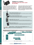
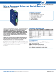
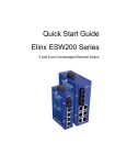
Peer-to-Peer and Modbus I/O
Zlinx Standard Wireless I/O
PRODUCT FEATURES
• Modular, Customizable Wire Replacement
• Flexible configuration for multiple types of analog/digital I/Os
• Software Selectable RF Transmit Power
• Software Selectable Over-the-air Data Rate
Zlinx™ Wireless Modbus I/O - flexible enough to fit your applications.
These plug-n-play units combine traditional Modbus RTU remote analog
and discrete I/O with built-in wireless connectivity. Wireless RTU serves as
Modbus slave RTU in radio-based SCADA systems, or as a peer-to-peer
communication platform.
Two Ranges Available - Short, Long range.
Active Repeaters - With built-in repeater functionality on 900 MHz -LR
models, you can ensure vital signals get through.
Modular - Just snap on your I/O and you are ready to communicate.
Wide Temperature - Meets most indoor or outdoor applications.
Rugged circuitry - prevents signal degradation.
128 / 256 Bit AES Encryption - Secures data.
Selectable RF Transmit Power - Allows you to optimize the transmitter
power for your application.
Selectable Over-the-air Data Rate - Allows you to decrease the OTA
Data Rate (on -LR and -LR-AU versions), effectively increasing the radio
transmitter’s range.
Exception Reporting - In Modbus mode, allows the reporting of possible
problems with connected devices.
Fail Safe - Allows you to set I/O to a safe state in the event of a
communications failure.
Calibration - Calculates correction factors to make I/O values better
match your sensor.
Communications Failure Alarm - Allows the first DO to be configured as
a COM failure alarm indicator.
Invert Output - You can invert the logic of all DO’s in peer-to-peer mode.
Monitor - Use the Zlinx™ Manager Software to monitor your I/O.
www.bb-elec.com
|
•
•
•
•
•
•
Modbus ASCII /RTU Compatible
900 MHz and 2.4 GHz Versions
Wide Operating Temperature
Active Repeater Functionality
10 to 40 VDC & 24 VAC Input Power
AES Encryption
Ordering Information
Model Number Description
ZZ8D-XX-LR Base Modules *
ZZ8D-NA-LR
868MHz, 2 AI, 2 A0, 2 DI, 2 D0 Sourcing, Long Range
ZZ8D-NB-LR
868MHz, 4 DI, 4 D0 Sourcing, Long Range
ZZ8D-NC-LR
868MHz, 2 AI, 2 A0, 2 DI, 2 D0 Sinking, Long Range
ZZ8D-ND-LR
868MHz, 4 DI, 4 D0 Sinking, Long Range
ZZ9D-XX-LR Base Modules *
ZZ9D-NA-LR
900MHz, 2 AI, 2 AO, 2 DI, 2 DO Sourcing, Long Range
ZZ9D-NA-LR-AU
900MHz, 2 AI, 2 AO, 2 DI, 2 DO Sourcing, Long Range
ZZ9D-NB-LR
900MHz, 4 DI, 4 DO Sourcing, Long Range
ZZ9D-NB-LR-AU
900MHz, 4 DI, 4 DO Sourcing, Long Range
ZZ9D-NC-LR
900MHz, 2 AI, 2 AO, 2 DI, 2 DO Sinking, Long Range
ZZ9D-NC-LR-AU
900MHz, 2 AI, 2 AO, 2 DI, 2 DO Sinking, Long Range
ZZ9D-ND-LR
900MHz, 4 DI, 4 DO Sinking, Long Range
ZZ9D-ND-LR-AU
900MHz, 4 DI, 4 DO Sinking, Long Range
ZZ24D-XX-SR Base Modules*
ZZ24D-NA-SR
2.4GHz, 2 AI, 2 AO, 2 DI, 2 DO Sourcing, Short Range
ZZ24D-NB-SR
2.4GHz, 4 DI, 4 DO Sourcing, Short Range
ZZ24D-NC-SR
2.4GHz, 2 AI, 2 AO, 2 DI, 2 DO Sinking, Short Range
ZZ24D-ND-SR
2.4GHz, 4 DI, 4 DO Sinking, Short Range
World-wide.
Check with your local distributor for availability and options.
* Check wireless regulations/standards in your geographic area.
Model Number Description
Expansion Modules
ZZ-8DI-DC
8 Digital Inputs, 10-48VDC
ZZ-8DO-T
8 Digital Outputs Sourcing
ZZ-8DO-T1
8 Digital Outputs Sinking
ZZ-8DO-R
8 Relay Outputs
ZZ-4AI
4 Analog Inputs
4 Passive Source Analog Inputs,
ZZ-4AO
Requires Isolated External Power Supply
ZZ-4AO-2
4 Analog Output Sourcing
ZZ-4RTD1
4 RTD Input
ZZ-4DI4DO-DCT
4 Digital Inputs, 10-48VDC, 4 Digital Outputs Sourcing
ZZ-4DI4DO-DCT1 4 Digital Inputs, 10-48VDC, 4 Digital Outputs Sinking
ZZ-2AI2AO
2 Analog Inputs, 2 Analog Outputs
Accessories
ZZ-PROG1-USB
Zlinx USB Programming Module, Cable, Software CD
ZZ24D-ANT1
2.4 GHz Spare Antenna
ZZ9D-ANT1
900 MHz Spare Antenna
ZZ-DIN 1
Replacement DIN Clip and Spring
ZZ-TB1
Replacement Terminal Block Kit
Zlinx Standard Wireless I/O_3713ds
Peer-to-Peer and Modbus I/O
Zlinx Standard Wireless I/O
Specifications
Base Module Radio Properties
Model No.
Frequency
Software Selectable RF Power Options
ZZ24D-Nx-SR
ZZ9D-Nx-LR
ZZ9D-Nx-LR-AU
ZZ8D-Nx-LR
2.4 GHz
900 MHz *
900 MHz *
868 MHz **
10mW, 16mW, 25mW, 40mW, 63mW
1mW,10mW, 100mW, 500mW, 1000mW
1mW, 10mW, 100mW, 500mW, 1000mW
1mW, 23mW, 100mW, 159mW, 316mW
Factory RF Power
Setting
63mW
1000mW
1000mW
316mW
AES Encryption
Over-the-air Data Rate
128 Bit
256 Bit
128 Bit
128 Bit
250 Kbps
9.6 or 115.2 Kbps
9.6 or 115.2 Kbps
24 Kbps
Note: ZZ9D-Nx-LR and ZZ9D-Nx-LR-AU have software selectable OTA data rates.
ZZ24D-Nx-SR
ZZ9D-Nx-LR
ZZ9D-Nx-LR-AU
ZZ8D-Nx-LR
Range w/Supplied Antenna (indoor / outdoor) maximum
300 Feet (91 Meters) / 1 Mile (1.6 Kilometers)
3000 Feet (914 Meters) / 14 Miles (23 Kilometers)
3000 Feet (914 Meters) / 14 Miles (23 Kilometers)
1800 Feet (549 Meters) / 25 Miles (40 Kilometers)
Range w/High Gain Antenna (Outdoor) maximum
N/A
40 Miles (64 Kilometers)
40 Miles (64 Kilometers)
25 Miles (40 Kilometers)
*Note: 900 MHz units are not sold in Europe
** Note: 868 MHz units are not sold in North America
Latency
Base Module
Modbus
Digital
8mS
9mS
ZZ24D-xx-SR
ZZ9D-xx-LR
Analog
15mS
104mS
Peer-to-Peer
Digital
20mS
55mS
Analog
25mS
52mS
Latency times were measured in a clean RF environment with devices less than 3 feet (1m) apart.
Add 45mS per analog expansion module and 25mS per digital expansion module.
ZZ8D-Nx-LR radios have a 10% maximum duty cycle.
I/O Points
Model No.
Digital Inputs
Digital Outputs
Analog Inputs
ZZxD-NA-xx (Base)
2 (Pull-up Resistors)
2 (Sourcing)
2 (mA, V)
ZZxD-NB-xx (Base)
4 (Pull-up Resistors)
4 (Sourcing)
--ZZxD-NC-xx (Base)
2 (Pull-up Resistors)
2(Sinking)
2 (mA, V)
ZZxD-ND-xx (Base)
4 (Pull-up Resistors)
4 (Sinking)
--ZZ-8DI-DC
8 (Pull-up Resistors)
----ZZ-8DO-T
--8 (Sourcing)
--ZZ-8DO-T1
--8 (Sinking)
--ZZ-4DI4DO-DCT
4 (Pull-up Resistors)
4 (Sourcing)
--ZZ-4DI4DO-DCT1
4 (Pull-up Resistors)
4 (Sinking)
--ZZ-4AI
----4 (mA, V)
ZZ-4AO
------ZZ-4A0-2
------ZZ-2AI2AO
----2 (mA, V)
ZZ-8DO-R
--8 (Relay)
--ZZ-4RTD1
----4 (RTD)
Software Programming Kits – Required to program your system
Model Number
Description
ZZ-PROG1-USB
Programming Module (USB Interface), USB cable and Software CD
Analog Outputs
2 (V, mA, Sinking)
--2 (V, mA, Sinking)
--------------4 (V, mA, Sinking)
4 (V, mA, Sourcing)
2 (V, mA, Sinking)
-----
Note: The Software CD is only available with the programming kit. Software and Firmware can also be downloaded at www.bb-elec.com
[email protected]
[email protected]
International Office: 707 Dayton Road PO Box 1040 Ottawa, IL 61350 USA 815-433-5100 Fax 433-5104
European Office: Westlink Commercial Park Oranmore Co. Galway Ireland +353 91 792444 Fax +353 91 792445
continued...
Peer-to-Peer and Modbus I/O
Zlinx Standard Wireless I/O
Specifications
Digital inputs
Voltage Range:
0 to 48 VDC
Low Voltage (0):
0.8 V maximum
High Voltage (1):
4.0 V minimum
Pull Up Current:
38 micro-amps
2 DI inputs per module
Software selectable as
Frequency Input:
frequency counters,
0 to 5 KHz range.
digital outputs
10 to 40 VDC (Sourcing)
Voltage Range:
0 to 48 VDC (Sinking)
40 mA per output
Relay outputs
Number of Relays:
8
Type:
C -normally open & normally closed
3.5mm removable terminal block
Output Connection:
(2 per output)
Common Connection:
3.5mm removable terminal block
250VAC @ 8A, 30VDC @5A (maximum per bank of 4
Ratings:
as grouped on the label)
radio properties (2.4 GHz - SR Models)
Frequency:
2.4 GHz
Output Power:
100 mW
Receiver Sensitivity:
-102 dbm
The included antenna is a 4.25 inch omni-directional
Antenna:
with RPSMA connector. (p/n ZZ24D-ANT1)
radio properties (900 MHx - LR Models)
Frequency:
900 MHz
Output Power:
1W
Receiver Sensitivity:
100 dbm @ 115.2 K, 110 dbm @ 9.6K
The included antenna is a 6.5 inch omni-directional
Antenna:
with RPSMA connector. (p/n ZZ9D-ANT1)
radio properties (868 mhz Lr Models)
Frequency:
868 MHz
Output Power:
315 mW
Receiver Sensitivity:
-112 dbm
The included antenna is a 6.5 inch omni-directional
Antenna:
with RPSMA connector. (p/n ZZ9D-ANT1)
led indicators
Tri-color – Off = No Signal
= Weak Signal
Receive Signal Strength: Red
Yellow = Medium Signal
Green = Strong Signal
Green – Blinks with TD or RD
RF Data:
Off = No Data
Green – Blinks with TD or RD
Local Bus Data:
Off = No Data
Red – On = Power applied
Power:
Off = No Power
www.bb-elec.com
|
Analog Inputs and Outputs
Ranges:
Resolution:
Input Accuracy:
Output Accuracy:
AI Load Resistance:
AO Max Output Current:
AO Max Load
RTD Inputs
Number of RTD:
Wire Configuration:
Type:
Input Connection:
Temperature Range:
0 to 10 VDC or 0 to 20 mA
ZZ-4AO-2 is an active current source. All
others are passive
12 Bit
0.2% full scale reading typical
0.27% full scale reading typical
100 Mega Ohms when configured for voltage
input 250 Ohms when configured for
current input
1 mA when configured for voltage output.
450 Ohms when configured for current output
@ 12V
4
2, 3, and 4 wire
PT100, PT1000 (Optimized for
temperature coefficient of 385 C),
Cu10 (Optimized for temperature
coefficient of 427 C)
3.5mm removable terminal block
(4 per output)
PT100 = (-) 200 to (+) 650 C
PT1000 = (-) 200 to (+) 100 C
Cu10 = (-) 100 to (+) 260 C
0.1C cross at (-) 40 to (+) 80 C
(+/-) 0.5 C typical
(+/-) 2.0 C maximum
Resolution:
Accuracy @ 25 C:
Accuracy (-)40 to (+) 80C
Environmental
Operating Temperature
ZZ-8DO-R
-40 to 55°C (-40 to 131°F)
All Others
-40 to 80°C (-40 to 176°F)
Maximum Ambient Air Temperature
ZZ-8DO-R
55°C (131°F)
All Others
80°C (176°F)
Storage Temperature
-40 to 85°C (-40 to 185°F)
Operating Humidity
0 to 95% Non-condensing
Enclosure
Plastic IP30
Mounting
35mm DIN Rail
1 Base Module supports up to 6 Expansion
Expansion
Modules
1.2 x 3.7 x 5.0 in
Dimensions
(2.9 x 9.3 x 12.7 cm)
Zlinx Standard Wireless I/O_3713ds
continued...
Peer-to-Peer and Modbus I/O
Zlinx Standard Wireless I/O
Specifications
Software
A software CD is provided with programming kits
Supported OS
and contains Zlinx Manager software, Users Manual
and Quick Start Guide.
Agency Approvals
FCC Part 15 Class A
Download DoC at www.bb-elec.com
CE
Download DoC at www.bb-elec.com
File Numbers E245458 (Class 1, Div 2) & E222870
(UL508)
Models that are Class 1/Division 2 listed:
ZZ24D-Nx-SR (2.4GHz, Short range)
ZZ9D-Nx-LR (900 MHz, Long range)
ZZ-2AI2AO
ZZ-4AI
ZZ-4AO
ZZ-4AO-2
ZZ-4DI4DO-DCT
ZZ-4DI4DO-DCT1
UL/cUL
ZZ-4RTD1
ZZ-8DI-DC
ZZ-8DO-R
ZZ-8DO-T
ZZ-8DO-T1
ZZ-PROG1-USB
Class 1, Division 2 exceptions:
ZZ-8DO-R is not UL508 listed.
ZZxxD-Nx-MR, ZZxxD-Nx-xR-AU and ZZ8D-Nx-xR
models are not Class 1, Division 2 Listed but are
UL508 listed.
MTBF (Hours)
ZZ24D-NA-SR
85547
ZZ24D-NB-SR
137106
ZZ24D-NC-SR
86247
ZZ24D-ND-SR
138362
ZZ24D-NA-MR
88006
ZZ24D-NB-MR
142946
ZZ24D-NC-MR
88746
ZZ24D-ND-MR
144909
ZZ9D-NA-MR
88006
ZZ9D-NB-MR
144746
ZZ9D-NC-MR
88746
ZZ9D-ND-MR
144909
ZZ9D-NA-LR
88195
ZZ9D-NB-LR
143446
ZZ9D-NC-LR
88938
ZZ9D-ND-LR
145422
ZZ8D-NA-LR
88195
ZZ8D-NB-LR
143446
ZZ8D-NC-LR
88938
ZZ8D-ND-LR
145422
ZZ-4AI
136050
ZZ-4AO
113996
ZZ-2AI2AO
119183
ZZ-8DI-T
317530
ZZ-8DO-T
313100
ZZ-8DO-T1
317530
ZZ-4DI4DO-DCT
197045
ZZ-4DI4DO-DCT1
200795
ZZ-8DO-R
40670
ZZ-4RTD1
243007
ZZ-4AO-2
113996
Zlinx Radio Modem & I/O Compatibility
Radio Modem
Zlinx Base I/O Module
ZP24D-250RM-SR
ZZ24D-Nx-SR
ZP9D-115RM-LR
ZZ9D-Nx-LR / ZZ9D-Nx-LR-AU
ZP8D-24RM-LR
ZZ8D-Nx-LR
[email protected]
[email protected]
Power (Base Modules)
Source
Voltage
Power Connection
Wiring Terminals
Wire Type
Conductors
Wire Range
Tightening Torque
Field Wiring Temp Rating
Power Consumption
SR Models
900 MHz LR Models
868 MHz LR Models
Power (Expansion Modules)
An external power supply is required
(not included)
10-40 VDC, 24 VAC
Class 2, (2.7A Maximum)
Removable Terminal Block, 3.81 mm spacing
Copper Wire Only
One Conductor Per Terminal
28 to 16 AWG
1.7 lb – in
105°C Minimum (Sized for 60°C ampacity).
10.0 W
9.5 W
12.0 W
Source
Class 2 Power Derived from base modules
Voltage and current listed on product label.
Power Consumption
ZZ-4AI
ZZ-4AO
ZZ-2AI2AO
ZZ-8DI-DC
ZZ-8DO-T
ZZ-8DO-T1
ZZ-4DI4DO-DCT
ZZ-4DI4DO-DCT1
ZZ-8DO-R
ZZ-4RTD1
ZZ-4AO-2
Outputs
1.0 W
1.1 W
1.2 W
0.4 W
15.8 W
1.1 W
8.1 W
1.0 W
3.2 W
0.4 W
6.0 W
ZZ-8DO-R
All Others
Wire Type
Conductors
Wire Size
Tightening Torque
Replacement Parts
ZZ-DIN1
ZZ-TB1
ZZ24D-ANT1
ZZ9D-ANT1
Relay Output, 250VAC
2 A General Purpose/Point
8 A General Purpose Total
Low Voltage, Limited Energy
Communications Protocol
Copper Wire Only
One Conductor Per Terminal 28 to 16 AWG
0.2 Nm (Newton-Meters)
Replacement DIN clip and spring for all ZZ
products, also comes with spare screws for
enclosure
Replacement terminal block kit for ZZ
products. Kit includes
(1) Two position TB (3.81mm)
(1) Four position TB (3.5mm)
(1) Eight position TB (3.5mm)
(1) Cover for local Bus
2.4 GHZ band antenna
900 MHz Spare Antenna
International Office: 707 Dayton Road PO Box 1040 Ottawa, IL 61350 USA 815-433-5100 Fax 433-5104
European Office: Westlink Commercial Park Oranmore Co. Galway Ireland +353 91 792444 Fax +353 91 792445