1
Intel® Solid-State Drive 320 Series
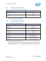
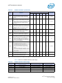
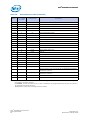
Table 11.
Serial ATA Power Pin Definitions — 2.5-inch Form Factor
Pin1
Function
Definition
2
Not connected
(3.3 V Power)
P22
Not connected
(3.3 V Power)
2
Not connected
(3.3 V Power; pre-charge)
P1
P3
Mating Order
2nd Mate
P43,4
Ground
1st Mate
P53
Ground
1st Mate
P63
Ground
1st Mate
3,5
V5
5 V Power
1st Mate
P83,5
V5
5 V Power
2nd Mate
P93,5
V5
5 V Power
2nd Mate
P103
Ground
P116
DAS
P7
P123, 4
1st Mate
Device Activity Signal
Ground
2nd Mate
1st Mate
7
V12
12 V Power; not used
1st Mate
P147
V12
12 V Power; not used
2nd Mate
P157
V12
12 V Power; not used
2nd Mate
P13
Notes:
1.
All pins are in a single row, with a 1.27 mm (0.050-inch) pitch.
2.
Pins P1, P2 and P3 are connected together, although they are not connected internally to the device. The host may put
3.3 V on these pins.
3.
The mating sequence is:
• the ground pins P4-P6, P10, P12 and the 5V power pin P7.
• the signal pins and the rest of the 5V power pins P8-P9.
4.
Ground connectors P4 and P12 may contact before the other 1st mate pins in both the power and signal connectors to
discharge ESD in a suitably configured backplane connector.
5.
Power pins P7, P8, and P9 are internally connected to one another within the device.
6.
The host may ground P11 if it is not used for Device Activity Signal (DAS).
7.
Pins P13, P14 and P15 are connected together, although they are not connected internally to the device. The host may put
12 V on these pins.
September 2011
Order Number: 325152-002US
Intel® Solid-State Drive 320 Series
Product Specification
15