1
Intel® Solid-State Drive 525 Series
Product Specification
Capacity: 30/60/120/180/240 GB
Components:
— Intel® 25nm NAND Flash Memory
— Multi-Level Cell (MLC)
Power Management
— 3.3 V SATA Supply Rail
— SATA Link Power Management (LPM)
Power
— Active (MobileMark* 2007 Workload):
300 mW (TYP)
— Idle: 250 mW (TYP)
Temperature
— Operating: 0o C to 70o C
— Non-Operating: -55o C to 95o C
Reliability
— Uncorrectable Bit Error Rate (UBER):
<1 sector per 1016 bits read
— Mean Time Between Failure (MTBF):
1,200,000 hours
— Shock (operating and non-operating):
1,000 G/0.5 msec
Form Factor: mSATA full size
Thickness: 3.7 mm
Weight: <10 grams
SATA 6Gb/s Bandwidth Performance1
(Iometer* Queue Depth 32)
— Sustained Sequential Read: up to 550
MB/s
— Sustained Sequential Write: up to 520
MB/s
Read and Write IOPS1
(Iometer Queue Depth 32)
— Random 4 KB Reads: Up to 50,000 IOPS
— Random 4 KB Writes: Up to 80,000 IOPS2
Latency (average sequential)
— Read: 80 µs (TYP)
— Write: 85 µs (TYP)
Vibration
— Operating: 2.17 GRMS (5-700 Hz)
— Non-operating: 3.13 GRMS (5-800 Hz)
Data Compression
AES 128-bit Encryption
End-to-end Data Protection
Compatibility
— Intel® SSD Toolbox with Intel® SSD
Optimizer
— Intel® Data Migration Software
— Intel® Rapid Storage Technology
— SATA Revision 3.0
— ACS-2
— SSD-enhanced SMART ATA feature set
— Native Command Queuing (NCQ)
command set
Data Set Management Command
Trim attribute
Certifications and Declarations:
— UL*
— CE*
— C-Tick*
— BSMI*
— KCC*
— Microsoft* WHCK
— VCCI*
— SATA-IO*
Product Ecological Compliance
RoHS*
1. Performance values vary by capacity.
2. Random 4 KB writes measured using out-of-box SSD.
Order Number: 328354-001US
December 2012
Intel® Solid-State Drive 525 Series
Ordering Information
Contact your local Intel sales representative for ordering information.
INFORMATION IN THIS DOCUMENT IS PROVIDED IN CONNECTION WITH INTEL PRODUCTS. NO LICENSE, EXPRESS OR IMPLIED, BY ESTOPPEL OR
OTHERWISE, TO ANY INTELLECTUAL PROPERTY RIGHTS IS GRANTED BY THIS DOCUMENT. EXCEPT AS PROVIDED IN INTEL'S TERMS AND CONDITIONS
OF SALE FOR SUCH PRODUCTS, INTEL ASSUMES NO LIABILITY WHATSOEVER AND INTEL DISCLAIMS ANY EXPRESS OR IMPLIED WARRANTY, RELATING
TO SALE AND/OR USE OF INTEL PRODUCTS INCLUDING LIABILITY OR WARRANTIES RELATING TO FITNESS FOR A PARTICULAR PURPOSE,
MERCHANTABILITY, OR INFRINGEMENT OF ANY PATENT, COPYRIGHT OR OTHER INTELLECTUAL PROPERTY RIGHT.
UNLESS OTHERWISE AGREED IN WRITING BY INTEL, THE INTEL PRODUCTS ARE NOT DESIGNED NOR INTENDED FOR ANY APPLICATION IN WHICH THE
FAILURE OF THE INTEL PRODUCT COULD CREATE A SITUATION WHERE PERSONAL INJURY OR DEATH MAY OCCUR.
Intel may make changes to specifications and product descriptions at any time, without notice. Designers must not rely on the absence or characteristics
of any features or instructions marked "reserved" or "undefined." Intel reserves these for future definition and shall have no responsibility whatsoever for
conflicts or incompatibilities arising from future changes to them. The information here is subject to change without notice. Do not finalize a design with
this information.
The products described in this document may contain design defects or errors known as errata which may cause the product to deviate from published
specifications. Current characterized errata are available on request.
Contact your local Intel sales office or your distributor to obtain the latest specifications and before placing your product order.
Copies of documents which have an order number and are referenced in this document, or other Intel literature, may be obtained by calling
1-800-548-4725, or go to: http://www.intel.com/design/literature.htm
Low Halogen applies only to brominated and chlorinated flame retardants (BFRs/CFRs) and PVC in the final product. Intel components as well as purchased
components on the finished assembly meet JS-709 requirements, and the PCB/substrate meet IEC 61249-2-21 requirements. The replacement of
halogenated flame retardants and/or PVC may not be better for the environment.
Intel and the Intel logo are trademarks of Intel Corporation in the U.S. and other countries.
*Other names and brands may be claimed as the property of others.
Copyright © 2012 Intel Corporation. All rights reserved.
Intel® Solid-State Drive 525 Series
Product Specification
2
December 2012
Order Number: 328354-001US
Intel® Solid-State Drive 525 Series
Contents
1.0
Overview ............................................................................................................................ 4
2.0
Product Specifications ......................................................................................................... 5
2.1
2.2
2.3
2.4
2.5
2.6
Capacity ............................................................................................................................... 5
Performance ........................................................................................................................ 5
Electrical Characteristics ..................................................................................................... 7
Environmental Conditions ................................................................................................... 7
Product Regulatory Compliance.......................................................................................... 8
Reliability ............................................................................................................................. 9
3.0
Mechanical Information .....................................................................................................10
4.0
Pin and Signal Descriptions .................................................................................................11
4.1
4.2
5.0
Pin Locations ..................................................................................................................... 11
Signal Descriptions ............................................................................................................ 11
Supported Command Sets ..................................................................................................13
5.1
5.2
5.3
5.4
5.5
5.6
5.7
5.8
5.9
5.10
5.11
5.12
5.13
ATA General Feature Command Set ................................................................................. 13
Power Management .......................................................................................................... 13
Security Mode Feature Set ................................................................................................ 14
SMART Command Set ....................................................................................................... 14
Device Statistics................................................................................................................. 18
SMART Command Transport (SCT).................................................................................... 18
Data Set Management Command Set ............................................................................... 18
Host Protected Area Command Set .................................................................................. 19
48-Bit Address Command Set............................................................................................ 19
General Purpose Log Command Set.................................................................................. 19
Native Command Queuing ................................................................................................ 19
Software Settings Preservation ......................................................................................... 20
SATA Link Power Management (LPM)............................................................................... 20
6.0
Certifications and Declarations ...........................................................................................21
7.0
References .........................................................................................................................22
8.0
Terms and Acronyms ..........................................................................................................22
9.0
Revision History .................................................................................................................23
Appendix: IDENTIFY DEVICE Command Data ..................................................................................24
December 2012
Order Number: 328354-001US
Intel® Solid-State Drive 525 Series
Product Specification
3
Intel® Solid-State Drive 525 Series
1.0
Overview
This document describes the specifications and capabilities of the Intel® Solid-State Drive 525 Series
(Intel® SSD 525 Series)1.
The Intel SSD 525 Series delivers small form-factor storage and leading performance for Serial
Advanced Technology Attachment (SATA)-based computers in capacities ranging from 30GB to 240GB.
By combining Intel's high quality 25nm NAND flash memory technology with SATA 6Gb/s interface support,
the Intel SSD 525 Series delivers sequential read speeds of up to 550 MB/s and sequential write speeds of
up to 520 MB/s.
The case-less mSATA (mini-SATA) design has a significantly smaller footprint than a 2.5-inch hard disk
drive (HDD), and enables fast read/write access times and a significant I/O and throughput
performance improvement as compared to HDDs. This design makes it ideal for new and innovative
small form factor computing platforms that have size and weight requirements that traditional 2.5-inch
or 1.8-inch HDDs cannot meet; such as, netbooks, thin-and-light systems, mini- and sub-notebooks,
all-in-one computers, and embedded platforms.
As compared to standard SATA HDDs, Intel SSD 525 Series offers these key features:
•
High I/O and throughput performance
•
Low power
•
Increased system responsiveness
•
High reliability
•
Enhanced ruggedness
•
Small form-factor
•
Minimum weight
The Intel SSD 525 Series also offers additional key features such as:
•
Advanced Encryption Standard (AES) 128-bit Encryption
AES 128-bit encryption is an industry standard in data security, providing a hardware-based
mechanism for encryption and decryption of user data. Utilizing a 128-bit encryption key, AES
encryption—when combined with an ATA drive password—helps protect user data.
•
End-to-End Data Protection
End-to-end data protection helps protect data from being corrupted across the data path by using
cyclic redundancy check (CRC), parity, and error correction code (ECC) checks in the data path
from the host interface to the NAND, and back.
•
Data Compression
Data compression helps improve performance and endurance by automatically compressing
information sent to the SSD so that less data has to be processed and stored on the NAND. The
amount of data that can be compressed depends on the type of data.
Note:
1. The Intel SSD 525 Series is currently not validated for data center usage.
Intel® Solid-State Drive 525 Series
Product Specification
4
December 2012
Order Number: 328354-001US
Intel® Solid-State Drive 525 Series
2.0
Product Specifications
2.1
Capacity
Table 1.
User Addressable Sectors
Unformatted Capacity
Intel SSD 525 Series
Note:
(Total User Addressable Sectors in LBA Mode)
30 GB
58,626,288
60 GB
117,231,408
120 GB
234,441,648
180 GB
351,651,888
240 GB
468,862,128
1 GB = 1,000,000,000 bytes; 1 sector = 512 bytes.
LBA count shown represents total user storage capacity and will remain the same throughout the life of the drive.
The total usable capacity of the SSD may be less than the total physical capacity because a small portion of the capacity is
used for NAND flash management and maintenance purposes.
2.2
Performance
The data compression engine in the Intel SSD 525 Series controller optimizes performance based on
the data pattern of the workload.
This section provides both compressible and incompressible Input/Output Operations Per Second
(IOPS) and sustained sequential read and write bandwidth specifications.
Table 2.
Compressible Performance
Intel SSD 525 Series
Specification
Unit
30 GB
60 GB
120 GB
180 GB
240 GB
Random 4 KB Read (up to)
IOPS
5,000
15,000
25,000
50,000
50,000
Random 4 KB Write (up to)1
IOPS
80,000
80,000
80,000
80,000
80,000
Random 4 KB Write (TYP)2
IOPS
10,000
23,000
40,000
60,000
60,000
Sequential Read (up to)3
SATA 6Gb/s
MB/s
500
280
550
280
550
280
550
280
550
280
275
475
500
520
520
240
245
260
260
260
SATA 3Gb/s
Sequential Write (up to)3
SATA 6Gb/s
SATA 3Gb/s
MB/s
Notes:
1.
Random 4 KB write performance measured using out-of-box SSD.
2.
Performance measured using Iometer* with Queue Depth 32. Measurements are performed on
8 GB of Logical Block Address (LBA) range on a full SSD.
3.
Performance measured using Iometer with Queue Depth 32.
December 2012
Order Number: 328354-001US
Intel® Solid-State Drive 525 Series
Product Specification
5
Intel® Solid-State Drive 525 Series
Table 3.
Incompressible Performance
Intel SSD 525 Series
Specification
Unit
30 GB
60 GB
120 GB
180 GB
240 GB
Random 4 KB Read (up to) 1
IOPS
7,000
12,000
24,000
46,000
46,000
Random 4 KB Write (up to) 1
IOPS
2,500
6,900
13,000
13,000
16,500
Sequential Read (up to) 1
MB/s
200
430
550
550
550
Sequential Write (up to) 1
MB/s
40
80
150
170
235
Notes:
1.
Performance measured using Iometer with Queue Depth 32. Measurements are performed on 8 GB of Logical Block Address
(LBA) range.
Table 4.
Latency
Specification
Latency1
Read
Write
Power On To Ready2
Intel SSD 525 Series
80 µs (TYP)
85 µs (TYP)
2 s (TYP)
Notes:
1.
Based on sequential 4 KB using Iometer with Queue Depth 1 workload with compressible (non-random) data pattern. Write
Cache Enabled.
2.
Power On To Ready time assumes proper shutdown.
Intel® Solid-State Drive 525 Series
Product Specification
6
December 2012
Order Number: 328354-001US
Intel® Solid-State Drive 525 Series
2.3
Electrical Characteristics
Table 5.
Operating Voltage and Power Consumption
Electrical Characteristics
Value
Operating Voltage for 3.3 V (±5%)
Min
3.14 V
Max
3.47 V
Power Consumption (TYP)
Active1
300 mW
Idle2
250 mW
Notes:
1.
Active power measured during execution of MobileMark* 2007 with SATA Link Power Management (LPM) enabled.
2.
Idle power defined as SSD at idle with SATA Link Power Management (LPM) enabled.
2.4
Environmental Conditions
Table 6.
Temperature, Shock, Vibration
Temperature
Module Temperature
Operating1
Non-operating
Temperature Gradient2
Operating
Non-operating
Humidity
Operating
Non-operating
Shock and Vibration
Range
0 – 70 oC
-55 – 95 oC
30 (TYP) oC/hr
30 (TYP) oC/hr
5 – 95 %
5 – 95 %
Range
Shock3
Operating
Non-operating
1,000 G (Max) at 0.5 msec
1,000 G (Max) at 0.5 msec
Vibration4
Operating
Non-operating
2.17 GRMS (5-700 Hz) Max
3.13 GRMS (5-800 Hz) Max
Notes:
1.
2.
3.
4.
As measured by temperature sensor, SMART Attribute BEh.
Temperature gradient measured without condensation.
Shock specifications assume that one side of SSD is inserted into SATA connector and the other side is secured by screw. Both
connector and screw are securely mounted on a fixture that is firmly attached on a shock table. The shock stimulus is applied
in X, Y and Z axis respectively. Shock specification is measured using peak acceleration and pulse width value.
Vibration specifications assume that one side of SSD is inserted into SATA connector and the other side is secured by screw.
Both connector and screw are securely mounted on a fixture that is firmly attached on vibration table. The vibration stimulus
is applied in X, Y and Z axis respectively Vibration specification is measured using G Root mean Squared (GRMS) value.
December 2012
Order Number: 328354-001US
Intel® Solid-State Drive 525 Series
Product Specification
7
Intel® Solid-State Drive 525 Series
2.5
Product Regulatory Compliance
The Intel SSD 525 Series meets or exceeds the regulatory or certification requirements in Product
Regulatory Compliance Specifications
Table 7.
Product Regulatory Compliance Specifications
Region for which
conformity declared
Title
Description
TITLE 47-Telecommunication CHAPTER I— FEDERAL
COMMUNICATIONS COMMISSION PART 15 — RADIO
FREQUENCY DEVICES
ICES-003, Issue 4 Interference-Causing Equipment
FCC Part 15B Class B
CAN/CSA-CEI/IEC CISPR 22:02. This is CISPR
Standard Digital Apparatus
IEC 555024 Information Technology Equipment —
Immunity characteristics — Limits and methods of
measurement CISPR 24:2010
EN-55022 Information technology equipment —
Radio disturbance characteristics — Limits and
methods of measurement CISPR 22:2008 (Modified)
EN-60950-1 2nd Edition
UL/CSA 60950-1 2nd Edition
Intel® Solid-State Drive 525 Series
Product Specification
8
USA
22:1997 with Canadian modifications.
Canada
EN-55024: 1998 and its amendments
European Union
EN-55022: 2006 and its amendments
European Union
Information Technology Equipment — Safety
—
Part 1: General Requirements
Information Technology Equipment — Safety
—
Part 1: General Requirements
USA / Canada
USA / Canada
December 2012
Order Number: 328354-001US
Intel® Solid-State Drive 525 Series
2.6
Reliability
The Intel SSD 525 Series meets or exceeds SSD endurance and data retention requirements as
specified in the JESD218 specification.
Reliability specifications are listed in Reliability Specifications.
Table 8.
Reliability Specifications
Parameter
Value
Uncorrectable Bit Error Rate (UBER)
Uncorrectable bit error rate will not exceed one sector in the specified
number of bits read. In the unlikely event of a nonrecoverable read
error, the SSD will report it as a read failure to the host; the sector in
error is considered corrupt and is not returned to the host.
< 1 sector per 1016 bits read
Mean Time Between Failures (MTBF)
1,200,000 hours
Mean Time Between Failures is estimated based on Telcordia*
methodology and demonstrated through Reliability Demonstration
Test (RDT).
Minimum Useful Life/Endurance Rating
Minimum useful life under typical client workloads with up to 20 GB of
host writes per day.
30 GB:
3 years
Other Capacities:
5 years
Insertion Cycles
250 insertion/removal cycles
Maximum insertion/removal cycles on mSATA/power cable.
December 2012
Order Number: 328354-001US
Intel® Solid-State Drive 525 Series
Product Specification
9
Intel® Solid-State Drive 525 Series
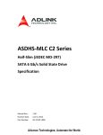
3.0
Mechanical Information
This figure shows the physical package information for the mSATA full size Intel SSD 525 Series. All
dimensions are in millimeters.
Figure 1. Dimensions for Intel SSD 525 Series
Intel® Solid-State Drive 525 Series
Product Specification
10
December 2012
Order Number: 328354-001US
Intel® Solid-State Drive 525 Series
4.0
Pin and Signal Descriptions
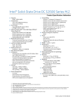
4.1
Pin Locations
Figure 3.
4.2
Layout of Signal and Power Segment Pins
Signal Descriptions
Table 9.
1
Serial ATA Power Pin Definitions
Pin
Function
Definition
P1
Reserved
No Connect
P2
+3.3 V
3.3 V Source
P3
Reserved
No Connect
P4
GND
Return Current Path
P5
Reserved
No Connect
P6
1
+1.5 V
1.5 V Source
P7
Reserved
No Connect
P8
Reserved
No Connect
GND
Return Current Path
P10
P9
Reserved
No Connect
P11
Reserved
No Connect
P12
Reserved
No Connect
P13
Reserved
No Connect
P14
Reserved
No Connect
P15
GND
Return Current Path
P16
Reserved
No Connect
P17
Reserved
No Connect
P18
GND
Return Current Path
P19
Reserved
No Connect
December 2012
Order Number: 328354-001US
Intel® Solid-State Drive 525 Series
Product Specification
11
Intel® Solid-State Drive 525 Series
Table 9.
1
Serial ATA Power Pin Definitions
Pin
Function
Definition
P20
Reserved
No Connect
P21
GND
Return Current Path
P22
Reserved
No Connect
P23
+B
Host Receiver Differential Signal Pair (This is an output of the SSD)
P24
+3.3 V
3.3 V Source
P25
-B
Host Receiver Differential Signal Pair (This is an output of the SSD)
P26
GND
Return Current Path
P27
GND
Return Current Path
+1.5 V
1.5 V Source
P28
1
P29
GND
Return Current Path
P302
Two Wire Interface
Two Wire Interface Clock
P31
-A
Host Transmitter Differential Signal Pair (This is an input of the SSD)
P32
2
Two Wire Interface
Two Wire Interface Data
P33
+A
Host Transmitter Differential Signal Pair (This is an input of the SSD)
P34
GND
Return Current Path
P35
GND
Return Current Path
P36
Reserved
No Connect
P37
GND
Return Current Path
P38
Reserved
No Connect
P39
+3.3 V
3.3 V Source
P40
GND
Return Current Path
P41
+3.3 V
3.3 V Source
P42
Reserved
No Connect
P43
Device Type
No Connect
P44
Reserved
No Connect
P453
Vendor
Vendor Specific / Manufacturing Pin
P46
Reserved
No Connect
3
Vendor
Vendor Specific / Manufacturing Pin
P481
+1.5 V
1.5 V Source
P49
DA/DSS
Device Activity Signal / Disable Staggered Spin-up
P50
GND
Return Current Path
Presence Detection
Shall be pulled to GND by device
+3.3 V
3.3 V Source
P47
P51
4
P52
Notes:
1.
1.5 V rail is not used on the Intel SSD 525 Series. No connect on the host side. Pin 6, 28, and 48 shall be unconnected on the
device side to avoid conflicts with wireless coexistence pins as specified in PCI Express Mini Card Specification.
2.
Pins 30 and 32 are intended for use as a two-wire interface to read a memory device to determine device information (an
example of this would be for use as SMB bus pins). These pins are not designed to be active in conjunction with the SATA signal
differential pairs. Not used on the Intel SSD 525 Series. No connect on the host side.
3.
Vendor-specific pins are not used in the Intel SSD 525 Series. No connect on the host side.
4.
Presence detection pin indicates presence of an mSATA device.
Intel® Solid-State Drive 525 Series
Product Specification
12
December 2012
Order Number: 328354-001US
Intel® Solid-State Drive 525 Series
5.0
Supported Command Sets
The Intel SSD 525 Series supports all mandatory Advanced Technology Attachment (ATA) and Serial
ATA (SATA) commands defined in the ACS-2 and SATA Revision 3.0 specifications. The mandatory and
optional commands are defined in this section.
5.1
ATA General Feature Command Set
General Feature command set (non-PACKET), which consists of:
• EXECUTE DEVICE DIAGNOSTIC
• FLUSH CACHE
• IDENTIFY DEVICE
Note:
•
•
•
•
•
•
•
•
•
•
See the Appendix for details on the sector data returned after issuing an IDENTIFY DEVICE command.
READ DMA
READ SECTOR(S)
READ VERIFY SECTOR(S)
SEEK
SET FEATURES
WRITE DMA
WRITE SECTOR(S)
READ MULTIPLE
SET MULTIPLE MODE
WRITE MULTIPLE
The Intel SSD 525 Series also supports the following optional commands:
• READ BUFFFER
• WRITE BUFFER
• NOP
• DOWNLOAD MICROCODE
5.2
Power Management
The Intel SSD 525 Series supports several power management feature sets as defined by the ATA
specification: general Power Management feature set, Advanced Power Management feature set, and
Power-Up In Standby (PUIS) feature set.
The Advanced Power Management and PUIS features can be enabled or disabled using the SET
FEATURES command.
The Power Management feature set includes the following commands:
• CHECK POWER MODE
• IDLE
• IDLE IMMEDIATE
• SLEEP
• STANDBY
• STANDBY IMMEDIATE
December 2012
Order Number: 328354-001US
Intel® Solid-State Drive 525 Series
Product Specification
13
Intel® Solid-State Drive 525 Series
5.3
Security Mode Feature Set
The Intel SSD 525 Series supports the Security Mode command set, which consists of:
•
SECURITY SET PASSWORD
•
SECURITY UNLOCK
•
SECURITY ERASE PREPARE
•
SECURITY ERASE UNIT
•
SECURITY FREEZE LOCK
•
SECURITY DISABLE PASSWORD
5.4
SMART Command Set
The Intel SSD 525 Series supports the SMART command set, which consists of:
•
SMART READ DATA
•
SMART READ ATTRIBUTE THRESHOLDS
•
SMART ENABLE/DISABLE ATTRIBUTE AUTOSAVE
•
SMART SAVE ATTRIBUTE VALUES
•
SMART EXECUTE OFF-LINE IMMEDIATE
•
SMART READ LOG SECTOR
•
SMART WRITE LOG SECTOR
•
SMART ENABLE OPERATIONS
•
SMART DISABLE OPERATIONS
•
SMART RETURN STATUS
Intel® Solid-State Drive 525 Series
Product Specification
14
December 2012
Order Number: 328354-001US
Intel® Solid-State Drive 525 Series
5.4.1
SMART Attributes
Table 10 lists the SMART attributes supported by the Intel SSD 525 Series; Table 11 lists the
corresponding status flags and threshold settings.
Table 10.
SMART Attributes
Status Flags1
ID
Attribute
Threshold
SP
EC
ER
PE
OC
PW
1
1
0
0
1
0
0 (none)
1
1
0
0
1
0
0 (none)
Power Cycle Count
The raw value of this attribute reports the
cumulative number of power cycle events
over the life of the device.
1
1
0
0
1
0
0 (none)
AAh
Available Reserved Space
1
1
0
0
1
1
10
ABh
Program Fail Count
The raw value of this attribute shows total
count of program fails and the normalized
value, beginning at 100, shows the percent
remaining of allowable program fails.
1
1
0
0
1
0
0 (none)
1
1
0
0
1
0
0 (none)
1
1
0
0
1
0
0 (none)
1
1
0
0
1
0
10
1
1
0
0
1
1
90
Re-allocated Sector Count
05h
The raw value of this attribute shows the
number of retired blocks since leaving the
factory (grown defect count).
Power-On Hours Count
The raw value reports two values: the first
4 bytes report the cumulative number of
power-on hours over the life of the device,
the remaining bytes report the number of
milliseconds since the last hour increment.
09h
0Ch
The On/Off status of the Device Initiated
Power Management (DIPM) feature will
affect the number of hours reported. If DIPM
is turned On, the recorded value for
power-on hours does not include the time
that the device is in a "slumber" state. If
DIPM is turned Off, the recorded value for
power-on hours should match the clock
time, as all three device states are counted:
active, idle and slumber.
Erase Fail Count
ACh
The raw value of this attribute shows total
count of erase fails and the normalized
value, beginning at 100, shows the percent
remaining of allowable erase fails.
Unexpected Power Loss
AEh
The raw value of this attribute reports the
cumulative number of unsafe (unclean)
shutdown events over the life of the device.
An unsafe shutdown occurs whenever the
device is powered off without STANDBY
IMMEDIATE being the last command
SATA Downshift Count
B7h
The count of the number of times SATA
interface selected lower signaling rate due
to error.
End-to-End Error Detection Count
B8h
Reports number of errors encountered
during end-to-end error detection within the
SSD data path.
December 2012
Order Number: 328354-001US
Intel® Solid-State Drive 525 Series
Product Specification
15
Intel® Solid-State Drive 525 Series
Table 10.
SMART Attributes
Status Flags1
ID
Attribute
Threshold
SP
EC
ER
PE
OC
PW
1
1
0
0
1
0
0 (none)
1
1
0
0
1
0
0(none)
1
1
0
0
1
0
0 (none)
1
1
0
0
1
0
0 (none)
1
1
0
0
1
0
0 (none)
1
1
0
0
1
0
0 (none)
1
1
0
0
1
0
0 (none)
1
1
0
0
1
0
0 (none)
1
1
0
0
1
1
10
Uncorrectable Error Count
BBh
The raw value shows the count of errors
that could not be recovered using Error
Correction Code (ECC).
Temperature
BEh
Reports real-time temperature of drive as
measured by temperature sensor on drive
PCB. The normalized value reports the
current temperature value. The raw value
shows current, lifetime highest and lifetime
lowest temperatures. Byte 1:0 = current
temp Celsius; Byte 3:2 = lifetime highest
temp Celsius; Byte 5:4 = lifetime lowest
temp Celsius.
Power-Off Retract Count (Unsafe Shutdown
Count)
C0h
C7h
The raw value of this attribute reports the
cumulative number of unsafe (unclean)
shutdown events over the life of the device.
An unsafe shutdown occurs whenever the
device is powered off without STANDBY
IMMEDIATE being the last command.
CRC Error Count
The total number of encountered SATA
interface cyclic redundancy check (CRC)
errors.
Host Writes
E1h
The raw value of this attribute reports the
total number of sectors written by the host
system. The raw value is increased by 1 for
every 65,536 sectors (32MB) written by
the host.
Timed Workload Media Wear
E2h
Measures the wear seen by the SSD (since
reset of the workload timer, attribute E4h),
as a percentage of the maximum rated
cycles.
Timed Workload Host Read/Write Ratio
E3h
Shows the percentage of I/O operations
that are read operations (since reset of the
workload timer, attribute E4h).
Timed Workload Timer
E4h
Measures the elapsed time (number of
minutes since starting this workload timer).
Available Reserved Space
E8h
This attribute reports the number of reserve
blocks remaining. The normalized value
begins at 100 (64h), which corresponds to
100 percent availability of the reserved
space. The threshold value for this attribute
is 10 percent availability.
Intel® Solid-State Drive 525 Series
Product Specification
16
December 2012
Order Number: 328354-001US
Intel® Solid-State Drive 525 Series
Table 10.
SMART Attributes
Status Flags1
ID
Attribute
Threshold
SP
EC
ER
PE
OC
PW
1
1
0
0
1
0
0 (none)
1
1
0
0
1
0
0 (none)
1
1
0
0
1
0
0 (none)
1
1
0
0
1
0
0 (none)
Media Wearout Indicator
This attribute reports the number of cycles
the NAND media has undergone. The
normalized value declines linearly from 100
to 1 as the average erase cycle count
increases from 0 to the maximum rated
cycles.
E9h
Once the normalized value reaches 1, the
number will not decrease, although it is likely
that significant additional wear can be put
on the device.
Total LBAs Written
The raw value of this attribute reports the
total number of sectors written by the host
system. The raw value is increased by 1 for
every 65,536 sectors (32MB) written by
the host.
F1h
Total LBAs Read
The raw value of this attribute reports the
total number of sectors read by the host
system. The raw value is increased by 1 for
every 65,536 sectors (32MB) read by
the host.
F2h
Total NAND Writes
Raw value reports the number of writes to
NAND in 1 GB increments.
F9h
Table 11 defines the SMART Attribute status flags.
Table 11.
SMART Attribute Status Flags
Status Flag
Description
Value = 0
Value = 1
5.4.2
SP
Self-preserving attribute
Not a self-preserving attribute
Self-preserving attribute
EC
Event count attribute
Not an event count attribute
Event count attribute
ER
Error rate attribute
Not an error rate attribute
Error rate attribute
PE
Performance attribute
Not a performance attribute
Performance attribute
OC
Online collection attribute
Collected only during offline
activity
Collected during both offline
and online activity
PW
Pre-fail warranty attribute
Advisory
Pre-fail
SMART Logs
The Intel SSD 525 Series implements the following Log Addresses: 00h, 02h, 03h, 06h, and 07h.
The Intel SSD 525 Series implements host vendor specific logs (addresses 80h-9Fh) as read and write
scratchpads, where the default value is zero (0). Intel SSD 525 Series does not write any specific values
to these logs unless directed by the host through the appropriate commands.
The Intel SSD 525 Series also implements a device vendor specific log at address A9h as a read-only log
area with a default value of zero (0).
December 2012
Order Number: 328354-001US
Intel® Solid-State Drive 525 Series
Product Specification
17
Intel® Solid-State Drive 525 Series
5.5
Device Statistics
In addition to the SMART attribute structure, statistics pertaining to the operation and health of the
Intel SSD 525 Series can be reported to the host on request through the Device Statistics log as defined
in the ATA specification.
The Device Statistics log is a read-only GPL/SMART log located at read log address 0x04 and is
accessible using READ LOG EXT, READ LOG DMA EXT or SMART READ LOG commands.
Table 12 lists the Device Statistics supported by the Intel SSD 525 Series.
Table 12.
Device Statistics Log
Page
Offset
0x00
-
0x01 - General Statistics
0x04 - General Errors Statistics
0x06 - Transport Statistics
0x07 - Solid State Device Statistics
5.6
Description
List of Supported Pages
Equivalent SMART attribute if
applicable
-
0x08
Power Cycle Count
0Ch
0x10
Power-On Hours
09h
0x18
Logical Sectors Written
E1h
0x20
Num Write Commands - incremented
by one for every host write command
0x28
Logical Sectors Read
0x30
Num Read Commands - incremented
by one for every host write command
0x08
Num Reported Uncorrectable Errors
0x10
Num Resets Between Command
Acceptance and Completion
-
0x08
Num Hardware Resets
-
0x10
Num ASR Events
-
0x18
Num Interface CRC Errors
0x08
Percentage Used Endurance Indicator
F2h
BBh
E9h
This statistic counts up from 0
rather than down from 100, and
may go beyond 100 for drives that
exceed their expected lifetime.
SMART Command Transport (SCT)
With SMART Command Transport (SCT), a host can send commands and data to an SSD and receive
status and data from an SSD using standard write/read commands to manipulate two SMART Logs:
•
Log Address E0h ("SCT Command/Status") — used to send commands and retrieve status
•
Log Address E1h ("SCT Data Transfer") — used to transport data
5.7
Data Set Management Command Set
The Intel SSD 525 Series supports the Data Set Management command set Trim attribute, which
consists of:
•
DATA SET MANAGEMENT
Intel® Solid-State Drive 525 Series
Product Specification
18
December 2012
Order Number: 328354-001US
Intel® Solid-State Drive 525 Series
5.8
Host Protected Area Command Set
The Intel SSD 525 Series supports the Host Protected Area command set, which consists of:
•
READ NATIVE MAX ADDRESS
•
SET MAX ADDRESS
•
READ NATIVE MAX ADDRESS EXT
•
SET MAX ADDRESS EXT
5.9
48-Bit Address Command Set
The Intel SSD 525 Series supports the 48-bit Address command set, which consists of:
•
FLUSH CACHE EXT
•
READ DMA EXT
•
READ NATIVE MAX ADDRESS
•
READ NATIVE MAX ADDRESS EXT
•
READ SECTOR(S) EXT
•
READ VERIFY SECTOR(S) EXT
•
SET MAX ADDRESS EXT
•
WRITE DMA EXT
•
WRITE MULTIPLE EXT
•
WRITE SECTOR(S) EXT
5.10
General Purpose Log Command Set
The Intel SSD 525 Series supports the General Purpose Log command set, which consists of:
•
READ LOG EXT
•
WRITE LOG EXT
•
READ LOG DMA EXT
•
WRITE LOG DMA EXT
5.11
Native Command Queuing
The Intel SSD 525 Series supports the Native Command Queuing (NCQ) command set, which includes:
•
•
Note:
READ FPDMA QUEUED
WRITE FPDMA QUEUED
With a maximum queue depth equal to 32.
December 2012
Order Number: 328354-001US
Intel® Solid-State Drive 525 Series
Product Specification
19
Intel® Solid-State Drive 525 Series
5.12
Software Settings Preservation
The Intel SSD 525 Series supports the SET FEATURES parameter to enable/disable the preservation of
software settings.
5.13
SATA Link Power Management (LPM)
The Intel SSD 525 Series supports the SET FEATURES parameter to enable Device Initiated Power
Management (DIPM). The SSD also supports Host Initiated Power Management (HIPM).
Intel® Solid-State Drive 525 Series
Product Specification
20
December 2012
Order Number: 328354-001US
Intel® Solid-State Drive 525 Series
6.0
Certifications and Declarations
Table 13 describes the Device Certifications supported by the Intel SSD 525 Series.
Table 13.
Device Certifications and Declarations
Certification
Description
Low Voltage DIRECTIVE 2006/95/EC OF THE EUROPEAN PARLIAMENT AND OF THE COUNCIL
CE Compliant
UL Certified
of 12 December 2006, and EMC Directive 2004/108/EC OF THE EUROPEAN PARLIAMENT AND OF THE
COUNCIL of 15 December 2004. Per EN 50581:2012 – Technical documentation for the assessment
of electrical and electronic products with respect to the restriction of hazardous substances.
Certified Underwriters Laboratories, Inc. Bi-National Component Recognition; UL 60950-1, 2nd
Edition, 2007-03-27 (Information Technology Equipment - Safety - Part 1: General Requirements)
CSA C22.2 No. 60950-1-07, 2nd Edition, 2007-03 (Information Technology Equipment - Safety - Part
1: General Requirements)
C-Tick Compliant
Compliance with the Australia/New Zealand Standard AS/NZS3548 and Electromagnetic
Compatibility (EMC) Framework requirements of the Australian Communication Authority (ACA).
BSMI Compliant
Compliance to the Taiwan EMC standard CNS 13438: Information technology equipment - Radio
disturbance Characteristics - limits and methods of measurement, as amended on June 1, 2006, is
harmonized with CISPR 22: 2005.04.
KCC
Compliance with paragraph 1 of Article 11 of the Electromagnetic Compatibility Control Regulation
and meets the Electromagnetic Compatibility (EMC) Framework requirements of the Radio Research
Laboratory (RRL) Ministry of Information and Communication Republic of Korea.
Microsoft WHCK
Microsoft Windows Hardware Certification Kit
RoHS Compliant
Restriction of Hazardous Substance Directive
VCCI
Voluntary Control Council for Interface to cope with disturbance problems caused by personal
computers or facsimile.
SATA-IO
Indicates certified logo program from Serial ATA International Organization.
Low Halogen
Applies only to brominated and chlorinated flame retardants (BFRs/CFRs) and PVC in the final
product. Intel components as well as purchased components on the finished assembly meet JS-709
requirements, and the PCB/substrate meet IEC 61249-2-21 requirements. The replacement of
halogenated flame retardants and/or PVC may not be better for the environment.
December 2012
Order Number: 328354-001US
Intel® Solid-State Drive 525 Series
Product Specification
21
Intel® Solid-State Drive 525 Series
7.0
References
Table 14 identifies the standards information referenced in this document.
Table 14.
Standards References
Date or
Rev. #
Title
Location
Sept 2010
Solid-State Drive (SSD) Requirements and Endurance Test Method
(JESD218)
http://www.jedec.org/standards-docume
nts/docs/jesd218/
Dec 2008
VCCI
http://www.vcci.jp/vcci_e/
June 2009
RoHS
http://qdms.intel.com/
Click Search MDDS Database and search
for material description datasheet
August 2009
ACS-2 Specification
http://www.t13.org/
June 2009
Serial ATA Revision 3.0
http://www.sata-io.org/
Oct 2010
JEDEC Solid-State Product Outline – mSATA SSD Assembly
http://www.jedec.org/
July 2011
Serial ATA Revision 3.1 (mSATA definition)
http://www.sata-io.org/
Compliance with EN 55022:1998 Information technology
equipment - Radio disturbance characteristics - Limits and methods
of measurement CISPR 22:1997 (Modified)
http://www.iec.ch/
8.0
Terms and Acronyms
Table 15 defines the terms and acronyms used in this document.
Table 15.
Glossary of Terms and Acronyms
Term
Definition
ATA
Advanced Technology Attachment
DAS
Device Activity Signal
DIPM
Device Initiated Power Management
DMA
Direct Memory Access
EXT
Extended
FPDMA
First Party Direct Memory Access
Gigabyte (1,000,000,000 bytes)
GB
Note: The total usable capacity of the SSD may be less than the total physical capacity because a small
portion of the capacity is used for NAND flash management and maintenance purposes.
HDD
Hard Disk Drive
Intel® Solid-State Drive 525 Series
Product Specification
22
December 2012
Order Number: 328354-001US
Intel® Solid-State Drive 525 Series
Table 15.
Glossary of Terms and Acronyms
Term
Definition
HIPM
Host Initiated Power Management
I/O
Input/Output
IOPS
Input/Output Operations Per Second
KB
Kilobyte (1,024 bytes)
LBA
Logical Block Address
LPM
Link Power Management
MB
Megabyte (1,000,000 bytes)
MLC
Multi-level Cell
MTBF
Mean Time Between Failures
NCQ
Native Command Queuing
NOP
No Operation
PIO
Programmed Input/Output
RDT
Reliability Demonstration Test
RMS
Root Mean Squared
SATA
Serial Advanced Technology Attachment
SMART
Self-Monitoring, Analysis and Reporting Technology
SSD
Solid-State Drive
TYP
Typical
UBER
Uncorrectable Bit Error Rate
9.0
Revision History
Date
Revision
December 2012
001
December 2012
Order Number: 328354-001US
Description
Initial release.
Intel® Solid-State Drive 525 Series
Product Specification
23
Intel® Solid-State Drive 525 Series
Appendix: IDENTIFY DEVICE Command Data
Table 16 details the sector data returned after issuing an IDENTIFY DEVICE command.
Table 16.
Word
Returned Sector Data
F = Fixed
V = Variable
X = Both
Default Value
Description
0
F
0040h
General configuration bit-significant information
1
X
3FFFh
Obsolete - Number of logical cylinders (16,383)
2
V
C837h
Specific configuration
3
X
0010h
Obsolete - Number of logical heads (16)
4-5
X
0h
6
X
003Fh
7-8
V
0h
Reserved for assignment by the CompactFlash* Association
(CFA)
9
X
0h
Retired
10-19
F
varies
20-21
X
0h
Retired
22
X
0h
Obsolete
23-26
F
varies
Firmware revision (8 ASCII characters)
27-46
F
varies
Model number (Intel® Solid-State Drive)
47
F
8010h
7:0—Maximum number of sectors transferred per interrupt on
multiple commands
48
F
4000h
Reserved
49
F
2F00h
Capabilities
50
F
4000h
Capabilities
51-52
X
0h
53
F
0007h
Words 88 and 70:64 valid
54
X
3FFFh
Obsolete - Number of logical cylinders (16,383)
55
X
0010h
Obsolete - Number of logical heads (16)
56
X
003Fh
Obsolete - Number of logical sectors per logical track (63)
57-58
X
00FBFC10h
Intel® Solid-State Drive 525 Series
Product Specification
24
Retired
Obsolete - Number of logical sectors per logical track (63)
Serial number (20 ASCII characters)
Obsolete
Obsolete
December 2012
Order Number: 328354-001US
Intel® Solid-State Drive 525 Series
Table 16.
Word
Returned Sector Data
F = Fixed
V = Variable
X = Both
Default Value
Description
59
V
0110h
Number of sectors transferred per interrupt on multiple
commands
60-61
F
varies
Total number of user-addressable sectors
62
X
0h
63
F
0007h
Multi-word DMA modes supported/selected
64
F
0003h
PIO modes supported
65
F
0078h
Minimum multiword DMA transfer cycle time per word
66
F
0078h
Manufacturer’s recommended multiword DMA transfer cycle time
67
F
0078h
Minimum PIO transfer cycle time without flow control
68
F
0078h
Minimum PIO transfer cycle time with IORDY flow control
69
F
4010h
Additional Supported
70
F
0h
Reserved
71-74
F
0h
Reserved for IDENTIFY PACKET DEVICE command
75
F
001Fh
Queue depth
76
F
070Eh
Serial ATA capabilities
77
F
0006h
Reserved for future Serial ATA definition
78
F
004Ch
Serial ATA features supported
79
V
0040h
Serial ATA features enabled
80
F
03FCh
Major version number
81
F
FFFFh
Minor version number
82
F
746Bh
Command set supported
83
F
7429h
Command sets supported
84
F
6163h
Command set/feature supported extension
85
V
7469h
Command set/feature enabled
86
V
B409h
Command set/feature enabled
87
V
6163h
Command set/feature default
88
V
207Fh
Ultra DMA Modes
89
F
0002h
Time required for security erase unit completion
December 2012
Order Number: 328354-001US
Obsolete
Intel® Solid-State Drive 525 Series
Product Specification
25
Intel® Solid-State Drive 525 Series
Table 16.
Word
Returned Sector Data
F = Fixed
V = Variable
X = Both
Default Value
Description
90
F
0001h
Time required for enhanced security erase completion
91
V
00FEh
Current advanced power management value
92
V
FFFEh
Master Password Revision Code
93
F
0h
Hardware reset result: the contents of bits (12:0) of this word
shall change only during the execution of a hardware reset
94
V
0h
Vendor’s recommended and actual acoustic management value
95
F
0h
Stream minimum request size
96
V
0h
Streaming transfer time - DMA
97
V
0h
Streaming access latency - DMA and PIO
98-99
F
0h
Streaming performance granularity
100-103
V
varies
104
V
0h
105
F
0001h
Reserved
106
F
4000h
Physical sector size / logical sector size
107
F
0h
108-111
F
varies
112-115
F
0h
Reserved for world wide name extension to 128 bits
116
V
0h
Reserved for technical report
117-118
F
0h
Words per logical sector
119
F
401Ch
Supported settings
120
F
401Ch
Command set/feature enabled/supported
121-126
F
0h
Reserved
127
F
0h
Removable Media Status Notification feature set support
128
V
0021h
Security status
129-159
X
varies
Vendor-specific
160
F
0h
CompactFlash Association (CFA) power mode 1
161-168
X
0h
Reserved for assignment by the CFA
169
X
0001h
Intel® Solid-State Drive 525 Series
Product Specification
26
Maximum user LBA for 48-bit address feature set
Streaming transfer time - PIO
Inter-seek delay for ISO-7779 acoustic testing in microseconds
Unique ID
Data set management Trim attribute support
December 2012
Order Number: 328354-001US
Intel® Solid-State Drive 525 Series
Table 16.
Word
Returned Sector Data
F = Fixed
V = Variable
X = Both
Default Value
Description
170-173
F
0h
Additional Product Identifier
174-175
F
0h
Reserved
176-205
V
0h
Current media serial number
206
X
0021h
207-208
X
0h
209
X
4000h
Alignment of logical blocks within a physical block
210-211
X
0h
Write-Read-Verify Sector Count Mode 3 (DWord)
212-213
X
0h
Write-Read-Verify Sector Count Mode 2 (DWord)
214
X
0h
NV Cache Capabilities
215-216
X
0h
NV Cache Size in Logical Blocks (DWord)
217
X
0001h
218
X
0h
Reserved
219
X
0h
NV Cache Options
220
X
0h
Write-Read-Verify feature set
221
X
0h
Reserved
222
X
103Fh
Transport major version number
223
X
0h
Transport minor version number
224-229
X
0h
Reserved
230-233
X
0h
Extended Number of User Addressable Sectors (QWord)
234
X
0002h
Minimum number of 512-byte data blocks per DOWNLOAD MICROCODE
command for mode 03h
235
X
0400h
Maximum number of 512-byte data blocks per DOWNLOAD MICROCODE
command for mode 03h
236-254
X
0h
255
X
varies
SCT Command Transport
Reserved
Nominal media rotation rate
Reserved
Integrity word
Notes:
F = Fixed. The content of the word is fixed and does not change. For removable media devices, these values may change when
media is removed or changed.
V = Variable. The state of at least one bit in a word is variable and may change depending on the state of the device or the
commands executed by the device.
X = F or V. The content of the word may be fixed or variable.
December 2012
Order Number: 328354-001US
Intel® Solid-State Drive 525 Series
Product Specification
27