1
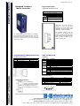
B&B ELECTRONICS
EIRx-Sx series-0106 - 1/2
Hardened Compact
Media Converter
Physical Description
Terminal Block and Power Inputs
Terminal Block Assignment
PWR1
GND
PWR2
GND
Power Input 1 (10 to 48VDC)
Power Ground
Power Input 2 (10 to 48VDC)
Power Ground
FAULT
1. The relay opens if PWR1 or PWR2 fails
2. The relay opens if the Port Link is Down
(When the Link Down Alarm is Enabled)
Earth Ground
While only one power source is
required to power up the media
converter, two power sources offer
redundancy for those mission critical
applications. (PWR1 and PWR2)
The terminals labeled Fault are
connected to a dry contact. The dry
contact is normally closed when either
power source is connected and active.
When no power is applied, the dry
contact is normally open.
installation
guide
describhow
d compact
This This
quickquick
installation
guide
describes
to installMedia
and
Converter.
Capable
of operating
at temperature
use the
hardened
compact
Media Converter.
Capable of
extremes
of -34 to +74°C,
this isofthe
converter
operating
at temperature
extremes
-34media
to +74°C,
this
harsh environments
by space.
is thechoice
mediaforconverter
of choice forconstrained
harsh environments
constrained by space.
10/100BaseTX and 100BaseFX Connectors
LED’s and DIP Switch
10/100BaseTX Connections:
Pin
Regular Ports
LED Status:
1
2
3
4
5
6
7
8
Receive Data + (input)
Receive Data – (input)
Transmit Data + (output)
NC
NC
Transmit Data – (output)
NC
NC
Uplink Port
Transmit Data + (output)
Transmit Data – (output)
Receive Data + (input)
NC
NC
Receive Data – (input)
NC
NC
LEDs
State
Indication
FAULT
Steady
Off
Steady
Off
Steady
Off
Steady
Off
Steady
Flashing
Off
Power or ports function abnormally
Power and ports function normally
Power on (PWR stands for POWER)
Power off
100Mbps network connection
10Mbps network connection
LFPT function enabled
LFPT function disabled
Network connection established(LNK stands for LINK)
Transmitting or receiving data(ACT stands for ACTIVITY)
Neither a network connection established nor
transmitting/receiving data
Connection in full duplex mode(FDX stands for FULL-DUPLEX)
Collision occurred(COL stands for COLLISION)
Connection in half-duplex mode
PWR1
PWR2
10/100
LFP
LNK/ACT
PRODUCT INFORMATION
FDX/COL
Steady
Flashing
Off
DIP Switch Settings:
100BaseFX Connections:
The Tx (transmit) port
of device 1 is connected to the Rx
(receive) port of device 2, and the
Rx (receive) port of device 1 to
the Tx (transmit) port of device 2.
Pos.
1
2
3
4
5
6
Down(0)
Disable Link-fault-pass-through
RJ45 Auto Negotiation Enabled
RJ45 Forced to 100Mbps
RJ45 Forced to Full Duplex
Fiber Forced to Full Duplex
Disable Link Down Alarm
Up(1)
Enable Link-fault-pass-through
RJ45 Forced Mode
RJ45 Forced to 10Mbps
RJ45 Forced to Half Duplex
Fiber Forced to Half Duplex
Enable Link Down Alarm
International Headquarters: 707 Dayton Road PO Box 1040 Ottawa, IL 61350 USA
815-433-5100 Fax 433-5104 www.bb-elec.com [email protected] [email protected]
European Headquarters: Westlink Commercial Park Oranmore Co. Galway Ireland
+353 91 792444 Fax +353 91 792445 www.bb-europe.com [email protected] [email protected]
B&B ELECTRONICS
EIRx-Sx series-0106 - 2/2
Link-fault-pass-through
Link-Fault-Pass-Through Overview
When two Media Converters are connected via their
fiber ports
Link Fault of the FX port:
A Link Fault condition will be sensed on the RJ45 port
whenever the media converter detects a Link Fault
condition on the Fiber port. (The 10/100, LNK/ACT, and
FDX/COL LED’s will be off.)
Assembly, Startup, and Dismantling
•
•
•
Assembly: Place the media converter on the DIN rail
from above using the slot. Push the front of the media
converter toward the mounting surface until it audibly
snaps into place.
Startup: Connect the supply voltage to start up the
media converter via the terminal block.
Dismantling: Pull out the lower edge and then remove
the media switch from the DIN rail.
Link Fault of the TX port:
The Media Converter A: A Link Fault condition will be
sensed on the FX port whenever the media converter
detects a Link Fault condition on the TX port. Thus, the
100, LNK/ACT, and FDX/COL LEDs of the TX port of the
Media Converter A would be off.
The Media Converter B: A Link Fault condition will be
informed to the FX port of the Media Converter B. Then
a Link Fault condition will be sensed on the TX port of
the Media Converter B whenever the Media Converter B
detects a Link Fault condition on the FX port. Thus, the
100, LNK/ACT, and FDX/COL LEDs of the Media
Converter B would be off.
Link Fault of the FX Port
TX Port
LEDs
FX Port
PWR 100 LNK/ACT FDX/COL LNK/ACT FDX/COL
Media Converter A ON
OFF OFF
OFF
OFF
OFF
Media Converter B ON
OFF OFF
OFF
OFF
OFF
Link Fault of the TX port of the Media Converter A
TX Port
LEDs
FX Port
PWR 100 LNK/ACT FDX/COL LNK/ACT FDX/COL
Media Converter A ON
OFF OFF
OFF
ON
ON
Media Converter B ON
OFF OFF
OFF
OFF
OFF
PRODUCT INFORMATION
Functional Description
Specifications
• Meets NEMA TS1/2 Environmental requirements
such as temperature, shock, and vibration for traffic
control equipment.
• Meets IEC61000-6-2 EMC Generic Standard
Immunity for industrial environment.
• One channel media converter between
10/100BaseTx and 100BaseFx
• Support 802.3/802.3u/802.3x. Auto-negotiation:
10/100Mbps, Full/half-duplex; Auto MDI/MDIX.
• 100BaseFX: Multi mode SC or ST type; Single mode
SC type.
• DIP switch for configuring link-fault-pass-through,
fixed speed, full/half duplex and link down alarm
• Store-and-forward mechanism
• Non-blocking full wire-speed forwarding rate
• Support broadcast storm filtering
• Back-pressure & IEEE 802.x compliant flow control
• Alarms for power failure by relay output.
• Redundant 10-48 VDC terminal block power inputs.
• Operating temperature ranges from -34 to 74°C.
• Supports DIN-rail mounting installation.
• Front panel LED status
Applicable Standards
Fixed Ports
Speed
IEEE 802.3 10BaseT,
IEEE 802.3u 100BaseTX & 100BaseFX
(1) TX port, (1) FX port
10BaseT
100BaseTX/FX
Switching Method
Forwarding rate
10/20Mbps for half/full-duplex
100/200Mbps for half/full-duplex
Store-and-Forward
14,880/148,800pps for 10/100Mbps
Cable
10BaseT
100BaseTX
100BaseFX
LED Indicators
2-pair UTP/STP Cat. 3, 4, 5 up to 100m
2-pair UTP/STP Cat. 5 up to 100m
MMF (50 or 62.5µm), SMF (9 or 10µm)
Per Unit - PWR1, PWR2, FAULT, LFP
Dimensions
Weight
Power
Power Consumption
Operating Temperature
Storage Temperature
Humidity
Emissions
Per Port - TX: LNK/ACT, FDX/COL, 100
FX: LNK/ACT, FDX/COL
2 x 4.3 x 5.4 in. (5 x 11 x 13.6cm)
0.6 Kg
Terminal Block: 200mA @ 24VDC, 10-48VDC
4.8W Max.
-34°C to 74°C
-45°C to 93°C
10 to 95%, non-condensing
FCC Part 15, Class A
CE: EN55022 (CISR22 Class A)
EN55024 (CISPR24 Class A)
Standards
ESD Standard (IEC 61000-4-2)
Radiated FRI Standards (IEC 61000-4-3)
Burst Standards (IEC 61000-4-4)
Surge Standards (IEC 61000-4-5)
Induced RFI Standards (IEC 61000-4-6)
Magnetic Field Standards (IEC 61000-4-8)
Voltage Dips Standards (IEC 61000-4-11)
Environmental Test Compliance:
Vibration Resistance (IEC 60068-2-6)
Shock (IEC 60068-2-27)
Free Fall (IEC 60068-2-32)
NEMA TS1/2 Environmental requirements for traffic control equipment
International Headquarters: 707 Dayton Road PO Box 1040 Ottawa, IL 61350 USA
815-433-5100 Fax 433-5104 www.bb-elec.com [email protected] [email protected]
European Headquarters: Westlink Commercial Park Oranmore Co. Galway Ireland
+353 91 792444 Fax +353 91 792445 www.bb-europe.com [email protected] [email protected]