1
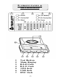
WireMaster XR-5
5 Cable Tester
www.triplett.com
CAUTION: Read, understand and follow all Safety
Rules and Operating Instructions in this instruction
manual before using this product.
84-851
CONTENTS
1. Introduction
2. Safety Rules and Warnings
3. Product Features
4. Specifications
5. Front Panel
6. Operation
7. Cable Repairs
8. Maintenance
9. Accessories
10. Warranty
1: INTRODUCTION
The Triplett WireMaster XR-5 tests 5 common LAN and
Computer cables. It tests installed cables or patch cords with
RJ-45, RJ-11, 1394, USB, and BNC connectors. It is intended
to test cables with straight through connections...... not cables
with reversed or transposed connections like some LAN
crossover cables or reverse wired telephone cables.
-1-
2: SAFETY RULES & WARNINGS
WARNING!!!
This tester is not intended for use on powered circuits.
Attaching this tester to a powered circuit can result in
damage to the tester or injury to the user.
2.1
Read all instructions in this manual before using this
tester. Failure to do so may result in damage to the tester
or injury to the user.
2.2
Do not use this tester with its case open, or with parts
removed. Doing so may damage the tester and/or injure
the user.
2.3
When using this tester in schools and workshops,
responsible teachers or skilled personnel must control the
usage of this tester. Failure to observe this precaution
may result in damage to the tester or injury to the user.
2.4
Follow the recommendations of any Trade Organizations
or Regulatory Agencies whose scope encompasses the
use of this tester. Failure to do so may result in damage to
the tester or injury to the user.
2.5
Do not open this tester for maintenance without first
disconnecting it from all external circuitry. Failure to
observe this precaution may result in damage to the tester
or injury to the user.
2.6
Repairs and maintenance must only be carried out by
qualified service personnel or qualified electricians /
technicians who know the dangers of, and the safety rules
applicable to this type of equipment. Failure to observe
this precaution may result in damage to the tester or
injury to the user.
2.7
Do not touch the ends of the cables when making tests.
An unexpected dangerous potential may be present.
Failure to observe this precaution may result in damage
to the tester or injury to the user.
2.8
Do not apply voltage or current to any of the tester's
connectors. Doing so may damage the tester and/or injure
the user.
-2-
2.9
This tester is not for use by children. Failure to observe
this precaution may result in damage to the tester or
injury to the user.
2.10 Do not use this tester to make measurements in adverse
environments such as rain, snow, fog, or locations with
steam, explosive gases or dusts.
2.11 Do not use tester in condensing atmospheres. That is, do
not use tester in conditions where ambient temperature
and humidity could cause condensation of water inside of
the tester.
2.12 Do not use this tester if it is wet, either from exposure to
the weather, or after cleaning the case of the tester.
2.13 Do not attempt immediate use of the tester when bringing
it from a cold environment to a warm environment.
Condensation of water, inside and outside of the tester,
may produce dangerous measuring conditions. Allow the
tester to warm to room temperature before using.
2.14 Do not modify this tester. Changing the design may make
the tester unsafe and may result in injury to the user.
2.15 Do not use the tester if it has undergone long-term
storage under unfavorable conditions.
2.16 Do not use the tester if it may have been damaged in
transport.
2.17 Avoid usage near strong magnetic fields (magnets,
loudspeakers, transformers, motors, coils, relays,
contactors, electromagnets, etc.). The tester may display
readings that are in error.
2.18 Avoid usage near strong electrostatic fields (high voltage
power lines, televisions, computer monitors, etc.). The
tester may display readings that are in error.
2.19 Avoid usage near strong RF fields (radio or television
transmitters, walkie talkies, cellular phones, etc.). The
tester may display readings that are in error.
2.20 Remove the battery when the tester may be left unused
for longer than 1 month. Chemical leakage from the
battery could damage the tester.
2.21 Do not use the tester if there is evidence of chemical
leakage from the battery.
-3-
3: PRODUCT FEATURES
3.1
3.2
3.3
3.4
3.5
3.6
3.7
3.8
3.9
3.10
3.11
3.12
Tests 5 types of cables
Simple one button test
Ergonomic portable handheld design
Tests installed wiring or patch cables
Remote unit stores on Main unit
600 ft test distance (RJ-45 / RJ-11 / BNC)
Convenient battery access
Built in battery test
LEDs indicate connections and faults
Beeper provides audible annunciation of test results
Tests shielded (STP) or unshielded (UTP) LAN cables
Tests shields in 1394 and USB cables
4: SPECIFICATIONS
4.1
Cables Tested:
UTP and STP LAN cables
terminated in RJ-45 male
connectors (EIA / TIA 568)
RJ-11 cables with male connectors,
2 to 6 conductors installed
1394 Cables with Type 1 plugs
on both ends
USB cables with Type A "flat"
plug on one end and Type B
"square" plug on other end
BNC cables with male connectors
4.2
Faults Indicated:
4.3
Low Battery
Annunciator: ..
Case
Dimensions:
(w/ Remote)
Weight:
(without battery)
Battery:
4.4
4.5
4.6
No Connection, Shorts,
Opens, Crosses
LED lights to indicate low battery
7.25 x 4.0 x 1.0 inches (L x W x H)
18.4 x 10.2 x 2.5 cm, (L x W x H)
202 grams, 0.445 lbs.
1 standard 9 volt alkaline battery,
Triplett Part Number 37-48
-4-
5: FRONT PANEL &
XR-5 DIAGRAM
1
2
3
4
5
6
7
Test Button
Main Display
RJ-45 Jack
RJ-11 Jack
1394 Jack
USB Jack
BNC Jack
-5-
6:
6.1
OPERATION
General Information:
The WireMaster XR-5 performs its tests when the single
button on its front panel is pressed and released. 6 Status
LEDs indicate the condition of the cable being tested, as
well as informing the user that Power is turned on, and
that the battery is good (or bad). 8 additional
"connection" LEDs light to indicate that specific wires in
a cable are connected. A chart beneath the 8 LEDs shows
the LEDs that should light for a good cable.
Note: Only one cable can be tested at a time. I.e. A BNC
cable and an RJ-45 cable cannot be tested
simultaneously.
6.2
The MAIN and REMOTE unit:
The WireMaster XR-5 consists of a Main unit and a
Remote unit. The Remote unit stores conveniently on the
bottom of the Main unit. It can be removed or replaced
by sliding it from left to right or right to left respectively.
Use care when removing or replacing the Remote some
of the plastic edges are a little sharp.
The Remote is often attached to the Main unit when
storing, when transporting, or when Patch cables are
being tested. The Remote is removed from the Main unit
when an installed (in wall, ceiling, etc.) cable is being
tested.
6.3
Testing Patch cables:
"Patch" cables have both ends accessible at the same
location. Usually, but
not always, these cables are less
than 25ft in length, and are not installed in a wall or
ceiling. Since both ends are accessible, one end can be
plugged
into the XR5's Main unit, and one end into
the Remote unit. It is not necessary to remove the
Remote unit from its "docked" position on the Main unit.
6.4
Testing Installed cables:
To test cables installed in ceilings or walls, or in
applications that prevent the ends from being in the same
location, the Remote can be detached from the
Main
unit. Once detached, the Remote can be attached to one
end a cable, and the Main unit attached to the other end
of the cable. These ends are often in different rooms and
on different floors of a building.
-6-
6.5
Performing the Test:
Once the Remote and Main unit are attached to the ends
of the subject cable, as described in 6.3 and 6.4, testing
may begin. Simply press and release the Test Button on
the Main unit, observe the LED indicators, and note the
beeping sound that comes from the Main unit.
6.6 Interpreting the Results:
6.6.1 Power LED:
The Power LED should light whenever the Test Button is
pressed and released. It will stay on for a minimum of 5
seconds, or for however long the Test Button is pressed.
If the Power LED does not light, replace the battery.
6.6.2 Low Battery LED:
The Low Battery LED should not light. If it does, replace
the battery.
6.6.3 No Connection LED / Single Beep
If the Remote is not connected to the Main unit with a
cable, or the cable has no intact conductors, the No
Connection LED with light and the Beeper will sound
once.
6.6.4 Connected LED / Lo-Hi Beep / Numbered LEDs
If the Connected LED lights and the Beeper emits a LoHi beep, examine the Numbered LEDs (i.e. LEDs
numbered 1 to 8, and the S/G LED).
The Numbered LEDs corresponding to the type of cable
being tested must light. Examine the table below the
Numbered LEDs, noting what LEDs should light. If all of
these LEDs do not light, the cable has an OPEN fault.
If all of the appropriate Numbered LEDs light, the
cable is OK.
Notes:
When testing an RJ-45 UTP cable, the S/G LED must not light.
When testing an RJ-45 STP cable, the S/G LED must light.
The XR-5 is intended to test complete cables. It may not find
faults in cables that are intentionally incomplete. For example,
the standard EIA / TIA 568 RJ-45 terminated Ethernet cable is
expected to contain 8 conductors. If only 4 conductors are used
between the RJ-45 connectors, the XR-5 may not properly
identify the faults.
RJ-11 cables may have 2 connections, 4 connections, or as
many as 6 connections. For 2 connection cables, LEDs 3 and 4
must light. For 4 connection cables, LEDs 2, 3, 4, and 5 must
light. For 6 connection cables, LEDs 1, 2, 3, 4, 5, and 6 must
light.
-7-
The Numbered LEDs DO NOT indicate that a GOOD
connection exists, only that a connection exists. If the Short or
Cross LEDs are lit, there is a fault in the cable.
6.6.5 Connected LED/3 Beeps/Short LED/Numbered LEDs
If the Connected LED lights, the Beeper emits 3 beeps,
and the Short LED lights, the cable has a fault. The
Numbered LEDs indicate the location of a short.
Note:
In the Short mode, the Numbered LEDs only indicate the
location of the shorts. The other connections in the cable are
not indicated. If more than 3 Numbered LEDs light, there may
be multiple shorts in the cable.
6.6.6 Connected LED/2 Beeps/Cross LED/Numbered LEDs
If the Connected LED lights, the Beeper emits 2 beeps,
and the Cross LED lights, the cable has a fault.
Notes:
In the Cross mode, the Numbered LEDs indicate connections
but do not indicate the location of the cross.
RJ-11 cables used for telephone connections are often crossed.
Even new cables are often crossed. This seldom affects the
performance of standard analog telephone lines (POTS).
Digital telephone lines and old touch tone phones may be
polarity sensitive, so a crossed cable may prevent them from
working properly.
7: Cable Repair
7.1
General Information: The following section provides
information to the user about common cable types,
common failures, and repairs. It is not meant to be an
exhaustive study of the topic, just some basic information
that the uninitiated may find helpful.
7.2
Cable damage: When a cable tests bad, either the wire
or the connectors or both may be at fault. If the cable has
been installed and working, then its likely that the wire
or connectors have been abused in some way. The wire
portion of the cable can be damaged by being crushed
(under the leg of a desk), stretched (pulled sharply
around a corner), punctured (by a nail or staple),
overvoltaged (hit by lightening), burned, etc. Similar
abuses will damage the connectors on the ends of the
-8-
cable. The connectors can also be damaged by excessive
insertion and removal or flexing of the cable close to
connector body.
While the WireMaster XR-5 can identify a bad cable, it
cannot determine if the wire or the connectors are at
fault. The user must examine the different parts of the
cable to determine the cause of failure and take the
appropriate steps to correct the problem.
7.3
Which end is bad? The XR-5, like many cable testers,
cannot find the location of the fault, or even determine
which end or connector is bad. It simply "knows" that a
fault exists. The user must locate the fault and take the
appropriate action.
7.4
Cables with Molded on ends: Many cables have molded
on ends that cannot be opened up for repair. The entire
cable must be replaced, or the molded on end removed
and replaced with a user serviceable connector. These
types of cables usually fail from Opens or Shorts. They
seldom fail from a Crossed connection.
7.5
Cables with Crimped on RJ connectors: Crimped on
RJ connectors cannot be reused or repaired. New
connectors must be installed on the cable. If the cable
being tested has just been "made up" or put in service,
and it tests as Open or Crossed, the RJ connectors have
probably been installed incorrectly. Shorts very seldom
occur as the result of a badly crimped RJ connector, so
the user should suspect a problem with the wire (possibly
a staple or nail through the wire, or a crushed or pinched
wire) if the XR-5 indicates a Short. A visual examination
of the RJ connectors may reveal the fault...... but keep in
mind that whatever the cause of a connector problem
(i.e., miswiring, improper stripping of the wire, bad
crimp, etc.), the only solution is to replace the connector.
Consequently, it is not necessary for the user to know
the exact cause of the problem, simply to make sure that
he installs the new connector correctly!
7.6
Conflicting Results: Sometimes, the tests results of the
XR-5 seem to conflict with the performance of the
cable........ i.e., the cable tests bad but works OK, or vice
versa. The following items list some of the reasons why.
7.6.1 The WireMaster XR-5 says my cable is bad, but my
LAN works OK: Installed LAN cables with RJ-45
connectors that have been in service and working OK
may test as Open, Shorted, or Crossed. Here's why.........
-9-
The EIA / TIA 568 standard for LAN cables only uses 4
of the wires in the eight wire cable. The other 4 wires in
the cable may have faults, but these will not affect the
operation of the LAN. The XR-5 tests all of the wires in
the LAN cable, and identifies the faults, even though
these wires may not be being used in the LAN system.
Not all LAN cables are wired "straight through".
Crossover cables used on LANs are purposely
"miswired", with their Receive and Transmit wires
"crossed over". The XR-5 will test this as a bad cable, but
it may work just fine as a Crossover cable.
7.6.2 The WireMaster XR-5 says my cable is good, but it
doesn't work on my LAN: Many cable testers like the
XR-5 only perform continuity style tests (Open, Short,
Crossed, etc.). Ethernet LAN cables are constructed in a
special way. The 8 wires inside are grouped into 4 pairs
of 2 wires each. Not only must the 8 wires connect
from end to end of the cable, the pairs in the cable must
connect to specific pins of the RJ-45 connectors. An
installer can crimp the RJ-45 plugs onto the ends of a
cable, ignoring the pairing (as described in EIA / TIA
568), and the cable will test OK. But when the cable is
tried on the LAN, it doesn't work. This is because the
lack of proper pairing causes excessive crosstalk in the
cable, preventing the LAN from working. This type of
cable fault is sometimes called a "split pair" or "double
split pair". To detect this type of fault, a more
sophisticated tester capable of performing a NEXT test
(Near End Cross Talk) must be used. Both the Triplett
PairMaster and LAN TDR can perform NEXT tests.
Note:
Crosstalk increases with the length of the cable. A LAN system
will tolerate a certain amount of crosstalk. A short cable (10ft
or less) that is improperly paired may work just fine. However,
longer cables, paired in exactly the same way, may not work.
This explains why an installer can make short jumper cables
that work (although they are improperly paired), but when he
installs RJ-45's in exactly the same way on a longer cable, the
cable does not work.
7.6.3 The WireMaster XR-5 says says my phone cable is
bad, but my phone works OK.
Most single line telephones only use 2 wires in a modular
cable. The modular cable, which terminates in RJ-11
connectors, could have as many as 6 wires in it. The
unused wires may have faults, which the XR-5 will
identify, but these faults may have no effect on the
working 2 wire telephone circuit.
-10-
Many telephone cables with RJ-11 plugs / jacks are wired
in reverse. The XR-5 will show that a cable like this is
Crossed. A cable like this reverses the polarity of the
telephone line. Most regular telephones made in the last
20 years are not polarity sensitive. So, even though the
cable is wired in reverse (crossed), it may work OK.
Early touch tone telephones and answering machines
were polarity sensitive. If connected in reverse polarity,
the touch tone phone may not dial out (no touch tone),
and the answering machine may not answer when the
line rings.
7.6.4 The WireMaster XR-5 says my RJ-11 phone cable is
good, but my phone doesn't work.
First, make sure the telephone line is hooked up and
"live" by using a tester like the Triplett Line Bug or Line
Bug 2. This simple tester will verify the presence of loop
current, and will test the polarity of the line.
The "good" cable may result in a reversed line. The Line
Bug will show reversed if this is the case. The line is not
actually being reversed in the good cable......its been
reversed somewhere else along the wire. Either the
reversed cable can be located and corrected, or, an often
used simpler approach is to replace the good cable with a
reversed cable, making the polarity come out correctly. It
is also worth knowing that some female/female couplers
reverse the polarity of the phone line.
Analog telephones will usually work, regardless of line
polarity. Digital phones are often polarity sensitive, and
may not work with reversed line polarity.
-11-
8: MAINTENANCE
Your Triplett WireMaster XR-5 is a precision test instrument
and, when used as described in this manual, should not require
maintenance. There are no internal adjustments. Calibration is
not required.
To clean the outside of the tester, use a cloth dampened with a
mild detergent solution. Do not use any abrasive cleansers, or
chemical solvents that may damage the case of the tester.
TRIPLETT PRODUCT RETURN INSTRUCTIONS
In the unlikely event that you must return your Triplett
equipment for repair, the following steps must be taken.
1) Call 1-800-TRIPLETT to obtain a Return Material
Authorization (RMA) number from Customer Service.
2) Enclose a copy of the original sales receipt showing date
of purchase.
3) Clearly print the RMA number on the outside of the
shipping container.
4) Return to: Triplett Corporation
One Triplett Drive
Bluffton, OH 45817
ATTN: Repair Dept.
Be sure to include a full description of the problem, and a
telephone number, street address, or email address, where you
can be contacted, and a return address where the meter can be
shipped to upon repair.
-12-
9: ACCESSORIES
9.1
The Triplett WireMaster XR-5 package contains the
following items:
WireMaster XR-5 Main Unit
WireMaster XR-5 Remote (PN: 3260-R)
Female BNC Terminator (PN: 26-940)
Male / Male BNC jumper cable (5"), (PN: 26-937)
Male / Male RJ-11 jumper cable, 4 wire (PN: 26-938)
Male / Male RJ-45 STP jumper cable, EIA / TIA 568,
(PN: 26-939)
9 volt battery (PN: 37-48)
Instruction Manual (PN: 84-851)
Carrying Case (PN: 10-4250)
-13-
10: WARRANTY
Triplett One Year Limited Warranty
The Triplett Corporation warrants instruments and test equipment
manufactured by it to be free from defective material or
workmanship and agrees to repair or replace such products which,
under normal use and service, disclose the defect to be the fault of
our manufacturing, with no charge within three years (one year on
calibration) of the date of original purchase for parts and labor. If
we are unable to repair or replace the product, we will make a
refund of the purchase price. Consult the Instruction Manual for
instructions regarding the proper use and servicing of instruments
and test equipment. Our obligation under this warranty is limited to
repairing, replacing, or making refund on any instrument or test
equipment which proves to be defective within three years from the
date of original purchase.
This warranty does not apply to any of our products which have
been repaired or altered by unauthorized persons in any way so as,
in our sole judgment, to injure their stability or reliability, or which
have been subject to misuse, abuse, misapplication, negligence,
accident or which have had the serial numbers altered, defaced, or
removed. Accessories, including batteries and fuses, not of our
manufacture used with this product are not covered by this
warranty.
To register a claim under the provisions of this warranty, contact
Triplett Corporation's Customer Service Department for a Return
Authorization Number (RMA) and return instructions. No returned
product will be accepted without an RMA number. Upon our
inspection of the product, we will advise you as to the disposition of
your claim.
ALL WARRANTIES IMPLIED BY LAW ARE HEREBY LIMITED TO
A PERIOD OF THREE YEARS (ONE YEAR ON CALIBRATION)
FROM DATE OF PURCHASE, AND THE PROVISIONS OF THE
WARRANTY ARE EXPRESSLY IN LIEU OF ANY OTHER
WARRANTIES EXPRESSED OR IMPLIED.
The purchaser agrees to assume all liability for any damages and
bodily injury which may result from the use or misuse of the
product by the purchaser, his employees, or others, and the
remedies provided for in this warranty are expressly in lieu of any
other liability Triplett Corporation may have, including incidental or
consequential damages.
Some states (USA ONLY) do not allow the exclusion or limitation of
incidental or consequential damages, so the above limitation or
exclusion may not apply to you. No representative of Triplett
Corporation or any other person is authorized to extend the liability
of Triplett Corporation in connection with the sale of its products
beyond the terms hereof.
Triplett Corporation reserves the right to discontinue models at any
time, or change specifications, price or design, without notice and
without incurring any obligation.
This warranty gives you specific legal rights, and you may have
other rights which vary from state to state.
-14-
Triplett Corporation
One Triplett Drive, Bluffton, OH 45817
PH: 419-358-5015 FAX: 419-358-7956
1-800-874-7538 www.triplett.com