1
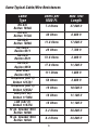
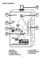
TRIPLETT
WireMaster
Coax
Instruction Manual
84-868
11/05
Table of Contents
Features ……………………........…...2
Introduction ………………….............3
Warnings and Cautions ………...........3
Specifications ………………..............4
Typical Cable/Wire Resistances ......... 5
Control Location ……………..............6
Getting Started ………………............7
Detailed Operation …………..............8
Included Items ……………….............11
Maintenance …………………............12
Warranty ………………………...........13
Features
•
•
•
•
•
•
•
•
•
•
•
•
•
•
8 way Mapper
8 numbered BNC Remotes included (can connect directly to BNC cables)
Male to Male BNC Adaptor included
Tests for Opens and Shorts
Audible and Visual Continuity Test
AC/DC Overvoltage Warning LED and Beeper
120VAC Line Cross Protection and Warning
Realtime test helps identify intermittents
Maps lengths over 20,000 ft (RG-6/U, 7.4 Ohms per 1000ft)
Identifies individual Remotes through Power Passive splitters
Battery Test
Uses common 9 volt battery (not included)
Power Latch Function Switch to prevent accidental turn-ons
Use to identify coaxial cables in CCTV Security and Surveillance systems, Broadcast
TV, Residential Video systems, and Cable TV (using appropriate adaptors).
• With appropriate adapters, use to identify any pair of wires (shielded or unshielded)
such as audio, video, telephone, etc.
• Carrying Case included
• One Year Warranty
2
Introduction
The Triplett Wiremaster Coax is an 8 way Cable Mapper, with built-in Continuity beeper,
and 120VAC line cross protection. BNC connectors on the Main Unit and the Remotes
allow the user to attach to BNC cables or outlets, and due to the variety of off-the-shelf
BNC adapters, to numerous other connector families.
Warnings and Cautions
• The WireMaster Coax is not intended for use as a voltage detector. It only detects
voltage in order to perform its intended function, and to prevent accidental damage to
the product. i.e. while the WireMaster Coax detects the presence of 120VAC, it is not
safe while doing so. The product and its connectors are not appropriately insulated.
• In some situations, unconnected wires can “float up” to potentially dangerous voltages and cause user injury. Treat any unknown wires as having dangerous voltage
present, and take the appropriate precautions.
• The overvoltage detection feature does not work with a low or dead battery. Consequently, if the battery is low or dead, the WireMaster Coax will not warn the user that a
potentially dangerous voltage (i.e. 120VAC) is present. The WireMaster Coax is not
intended for use as a voltage detector.
3
Specifications
•
•
•
•
•
•
•
•
•
•
•
•
•
Identifies 8 individual Remotes by measuring their precision resistance
AC and DC test detects voltages above 3 volts
Display: Bright Red and Green LEDs indicate the test results
Protected against damage up to 120 volts AC/DC (no fuse required)
Minimum cable length: no minimum
Maximum cable length: any length whose total DC resistance is less than 200 Ohms
(see table)
Cables / Wires Tested: Any pair whose total DC resistance is less than 200 Ohms, and
is unconnected to other equipment or circuitry
Continuity: Continuity (SHORT) is indicated for resistances of 500 Ohms or less
OPEN Test: OPEN is indicated for resistances of 10,000 Ohms or more
Battery: 9 volt
Battery Life: approx 20 hours continuous use (alkaline battery)
Size:
Main Unit: 2.45" W x 4.5" H (to top of BNC) x 1.25" T (to top of switch)
Remote: 0.5” W x 1.25” H
Weight: Main Unit (with battery): 4.6 oz.
Complete Kit: 11.8 oz.
Note:
The WireMaster Coax will not map cables if any of the following devices are in use:
• Amplifiers
• Electronic Switches
• Attenuators
• Matching Transformers
• Baluns
• Modulators
• DC Blockers
• Power Dividers
• Directional Taps
• Splitters (non power passive)
4
Some Typical Cable/Wire Resistances
Cable
Type
RG-6/U
Belden 1694A
RG-6/U
Belden 1152A
RG-58/U
Belden 7806A
RG-58A/U
Belden 9311
RG-59/U
Belden 8241
RG-59/U
Belden 9659
Mini Coax
Belden 9221
Telephone (CAT 3)
Belden 1227A1
Telephone (CAT 3)
Belden 1245A2
LAN (CAT 5e)
Belden 11700A
LAN (CAT 6)
Belden 11872A
12 ga. Speaker Wire
Belden 1860A
16 ga. Speaker Wire
Belden 1862A
Ohms per
1000 Ft.
Max Test
Length
7.4 Ohms
27,000 ft
30 Ohms
6,600 ft
11.8 Ohms
17,000 ft
26 Ohms
7,700 ft
51.6 Ohms
3,900 ft
17.6 Ohms
11,300 ft
111 Ohms
1,800 ft
56 Ohms
3,600 ft
19 Ohms
10,500 ft
18 Ohms
11,100 ft
18 Ohms
11,100 ft
3.2 Ohms
58,800 ft
8.4 Ohms
23,800 ft
5
Control Locations
G
A
F
B
E
C
D
A: Open LED
B: Unlock Button
C: Function Switch
D: Overload / Voltage LED
E: 1 thru 8 ID LED’s
F: Short/Continuity LED
G: BNC Connector
6
Getting Started
Installing / Replacing Battery
To install or replace the 9 volt battery, remove the single screw from the back of the
case. Gently remove the front of the case to gain access to the battery compartment.
Sometimes it helps to press lightly on the numbered LEDs to remove the front. With the
front removed, install/replace battery. Replace front, aligning LEDs in their respective
holes, and replace screw.
Power Latch
The WireMaster Coax Function switch incorporates a Power Latch feature to prevent
the product from accidentally being turned on, which could result in a dead battery.
Note that the Function switch is locked into the OFF: OVERLOAD / VOLTAGE position. To
turn the product on, the UNLOCK button must be pressed, and while the button is
pressed, the Function switch is moved to the CABLE MAP position, at which time the
UNLOCK button may be released. When the Function switch is returned to the OFF:
OVERLOAD / VOLTAGE position, the switch will lock in this position, requiring the user
to once again press the UNLOCK button to turn the product on.
Battery Test
Press the UNLOCK button and set the Function switch to the CABLE MAP position. The
green BATTERY TEST LED must flash. If the BATTERY TEST LED does not flash, the
battery should be replaced. If it is weak, it may produce erroneous results in the CABLE
MAP mode.
Note: The BATTERY TEST LED does not stay on. It only tests the battery when the
product is first turned on. To test the battery again, turn the product off and back on.
Verifying Product Operation
After turning the product on, connect the provided BNC to BNC adaptor to the BNC on
the WireMaster Coax. Experimentally connect different numbered Remotes to the adaptor, noting that the number on the Remote agrees with the LED that lights on the
WireMaster Coax. In use, thousands of feet of wire may be between the Remote and
the WireMaster Coax, and the Remote will cause the appropriate LED to light.
7
Detailed Operation
Identifying Cables (Mapping)
The WireMaster Coax will not work if AC or DC voltage is present. Some coaxial cables
have AC or DC voltage on them to operate amplifiers, preamplifiers, LNB’s, etc. The
OFF: OVERLOAD / VOLTAGE test position of the Function switch tests the connected
cable for the presence of AC or DC voltage.
The WireMaster Coax is intended for use on un-terminated cables . . . that is, cables
without any devices connected to them.
Before connecting any Remotes to cables, connect the WireMaster Coax, with its Function switch set to OFF: OVERLOAD / VOLTAGE, to each of the cables to be mapped. If
there is an AC or DC (plus) voltage present, the OVERLOAD / VOLTAGE indicator LED
will light and the warning beeper will sound intermittently. If this occurs, the cable(s)
cannot be Mapped / Identified (ID’ed) with the WireMaster Coax.
When it has been determined that no AC or DC voltage is present, connect the various
Remotes to the cables to be ID’ed
Press the UNLOCK button and set the Function switch to the CABLE MAP position. The
green BATTERY TEST LED must flash. The OPEN LED must light. If the OPEN LED does
not light, there may be a defect in the WireMaster Coax that will prevent it from correctly ID’ing a cable. Check or replace the battery before proceeding.
At the ends of the target cables opposite the Remotes, connect the WireMaster Coax,
in succession, to each cable, noting the ID number of the LED that lights.
If upon connecting the WireMaster Coax to a cable, the OPEN LED remains lit, the
cable may not have a Remote at its opposite end, an open fault may be present in the
cable, or a splitter may be present in the cable. The WireMaster Coax will not work
through splitters, amplifiers, or any other DC blocking devices.
If the SHORT / CONTINUITY LED lights and the beeper sounds, the cable may be shorted,
or some device is connected to the cable that appears as a short to the WireMaster
Coax.
8
If the OVERLOAD / VOLTAGE LED lights and the beeper sounds, at any time, the cable
being tested has voltage on it and cannot be ID’ed.
If a number of ID LEDs light simultaneously, a stray voltage may be present that will
prevent the cable from being ID’ed.
Mapping Cables with Different Connectors or Cables without Connectors
Most non-faulted cables containing 2 conductors or more can be mapped. Even single
conductors can be mapped if a low resistance ground or return path is available.
Almost any off-the-shelf BNC adaptor can be used with the WireMaster Coax. They are
often available through electronic supply houses or Do-It-Yourself outlets. Using these
adaptors, the BNC connectors on the WireMaster Coax can be adapted to most coaxial
connectors (F, TNC, SMA, RCA Phono, 1/8" and 1/4" phone jack, PL-259, etc.) Even
adaptors from BNC to RJ-11 or RJ-45 are available, but not as common as other types.
With BNC test cables terminated in alligator clips, wires without connectors can be
tested. Just clip the alligators onto the pair of wires to be ID’ed at the Remote and at the
WireMaster Coax.
If a low resistance ground or return path is available at both the Remote location and at
the WireMaster Coax location, single wires can be ID’ed. Connect one alligator clip at
both locations to the ground. Connect the other clip to the wire(s) to be ID’ed. ID the
wires at the WireMaster Coax by connecting the remaining alligator clip to each wire
and noting the displayed ID.
Note: If the ground or return path has too much resistance, or has AC or DC current
flowing in it, incorrect ID’s may be obtained.
9
Mapping Cables through a Splitter
The WireMaster Coax will map individual Remotes through a fully power passive splitter. Most splitters, like those used in CATV (Cable Television) are not power passive.
Some splitters are not power passive through all of their ports (partially passive). Satellite splitters and high quality splitters are often power passive, but not necessarily
through all of the ports.
For distribution systems using fully power passive splitters, the WireMaster Coax will
map individual Remotes through the splitters. Only one Remote at a time can be mapped.
Connecting more than one Remote at a time to the system will cause an incorrect ID on
the WireMaster Coax. Some equipment connected to the outputs of the splitters may
cause the WireMaster Coax to produce an incorrect ID. If in doubt, disconnect the
equipment.
Most consumer satellite distribution systems which use splitters are equipped with F
connectors, so several BNC to F adaptors are needed. Since only one Remote can be
mapped at a time, only two adaptors are needed . . . one for the chosen Remote, and
one for the WireMaster Coax.
Splitters are bi-directional . . . meaning that signals pass through them in both directions. Because of this behavior, the Remote can be connected to any port on the splitter,
and it can be “seen” on any other port.
A typical test would be to connect the chosen Remote to the input of the system, and
test at each outlet with the WireMaster Coax for the presence of the Remote’s ID. If the
correct ID is displayed, the system’s input is connected to the tested outlet. If OPEN or
SHORT is displayed, there may be no connection to the Remote, power passive splitters are not being used, or equipment connected to the splitters is interfering with the
ID.
Note: The WireMaster Coax will not test through active devices (amplifiers, switches,
modulators, etc.) or DC Blocks, Matching Transformers, or any other device that will
not pass the DC test signal or alters the characteristics of the signal.
10
Continuity Testing
The WireMaster Coax can be used as an audible and visual Continuity tester. To use
this feature, the user will need to purchase or make a simple BNC / Clip Lead adaptor.
(Triplett PN: 79-792)
Connect the adaptor cable to the BNC on the WireMaster Coax. When a circuit with
Continuity is connected between the adaptor’s clip leads, the product’s SHORT / CONTINUITY LED will light and the beeper will sound.
Intermittent Connections
The WireMaster Coax performs tests in real-time. That is, it is continuously testing the
target cable for the presence of a Remote (some products only perform a momentary
test). When a cable is suspected of having an intermittent connection, a Remote can be
connected to one end of the cable, and the WireMaster Coax connected to the opposite
end of the cable. The appropriate numbered ID LED should light on the WireMaster
Coax. Flex the cable at its connectors and along its length (may require 2 people) while
observing the ID LED on the WireMaster Coax. If an intermittent connection is found,
the ID LED will flicker or change value (like to SHORT or OPEN).
Included Items
The following items are included with the WireMaster Coax
Remote 1 ……………………………... Triplett PN: 3274-1
Remote 2 ……………………………... Triplett PN: 3274-2
Remote 3 ……………………………... Triplett PN: 3274-3
Remote 4 ……………………………... Triplett PN: 3274-4
Remote 5 ……………………………... Triplett PN: 3274-5
Remote 6 ………………………….….. Triplett PN: 3274-6
Remote 7 ………………………….….. Triplett PN: 3274-7
Remote 8 ……………………………... Triplett PN: 3274-8
Carrying Case with Foam Insert …….... Triplett PN: 10-4293
Male BNC to BNC Adaptor …………..... Triplett PN: 13838
Also Available:
BNC to Alligator Clip Lead .................... Triplett PN: 79-792
11
Maintenance
No regular maintenance of the WireMaster Coax is required. In the event the product is
defective or is damaged, please contact TTT for repair information.
TRIPLETT PRODUCT RETURN INSTRUCTIONS
In the unlikely event that you must return your Triplett equipment for
repair, the following steps must be taken.
1) Call 1-800-TRIPLETT to obtain a Return Material
Authorization (RMA) number from Customer Service.
2) Enclose a copy of the original sales receipt showing date of purchase.
3) Clearly print the RMA number on the outside of the shipping container.
4) Return to:
Triplett Corporation
One Triplett Drive
Bluffton, OH 45817
ATTN: Repair Dept.
12
Triplett One Year Limited Warranty
The Triplett Corporation warrants instruments and test equipment manufactured by it to be
free from defective material or workmanship and agrees to repair or replace such products
which, under normal use and service, disclose the defect to be the fault of our manufacturing,
with no charge within one year of the date of original purchase for parts and labor. If we
are unable to repair or replace the product, we will make a refund of the purchase price.
Consult the Instruction Manual for instructions regarding the proper use and servicing of
instruments and test equipment. Our obligation under this warranty is limited to repairing,
replacing, or making refund on any instrument or test equipment which proves to be defective
within one year from the date of original purchase.
This warranty does not apply to any of our products which have been repaired or altered
by unauthorized persons in any way so as, in our sole judgment, to injure their stability or
reliability, or which have been subject to misuse, abuse, misapplication, negligence, accident
or which have had the serial numbers altered, defaced, or removed. Accessories, including
batteries and fuses, not of our manufacture used with this product are not covered by this
warranty.
To register a claim under the provisions of this warranty, contact Triplett Corporation’s
Customer Service Department for a Return Authorization Number (RMA) and return
instructions. No returned product will be accepted without an RMA number. Upon our
inspection of the product, we will advise you as to the disposition of your claim.
ALL WARRANTIES IMPLIED BY LAW ARE HEREBY LIMITED TO A PERIOD OF ONE
YEAR FROM DATE OF PURCHASE, AND THE PROVISIONS OF THE WARRANTY ARE
EXPRESSLY IN LIEU OF ANY OTHER WARRANTIES EXPRESSED OR IMPLIED.
The purchaser agrees to assume all liability for any damages and bodily injury which may
result from the use or misuse of the product by the purchaser, his employees, or others,
and the remedies provided for in this warranty are expressly in lieu of any other liability
Triplett Corporation may have, including incidental or consequential damages.
Some states (USA ONLY) do not allow the exclusion or limitation of incidental or
consequential damages, so the above limitation or exclusion may not apply to you. No
representative of Triplett Corporation or any other person is authorized to extend the liability
of Triplett Corporation in connection with the sale of its products beyond the terms hereof.
Triplett Corporation reserves the right to discontinue models at any time, or change
specifications, price or design, without notice and without incurring any obligation.
This warranty gives you specific legal rights, and you may have other rights which vary
from state to state.
13
Triplett Corporation One Triplett Drive Bluffton, OH 45817
800-TRIPLETT
FAX: 419-358-7956
www.triplett.com
© Triplett Corporation
All Rights Reserved