1
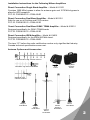
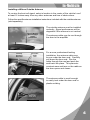
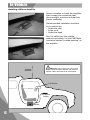
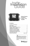
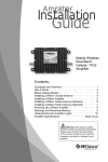
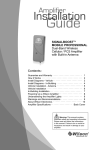
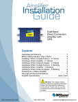
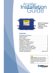
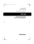
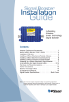
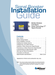
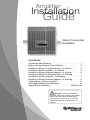
Amplifier
Installation
stallat
stallatio
Guide
Direct Connection
Amplifiers
Contents:
Guarantee and Warranty · · · · · · · · · · · · · · · · · · · · · · · · 1
Before Getting Started / How it Works · · · · · · · · · · · · · · 3
Installing a Wilson Outside Antenna - In-Vehicle · · · · · · 4
Installing a Wilson Amplifier - In-Vehicle · · · · · · · · · · · · 5
Installing a Wilson External Adapter - In-Vehicle · · · · · · 6
Installing a Wilson Outside Antenna - In-Building · · · · · 7
Installing a Wilson Amplifier - In-Building · · · · · · · · · · · · 7
Installing a Wilson External Adapter - In-Building · · · · · 8
Powering Up a Wilson Amplifier · · · · · · · · · · · · · · · · · · · 9
Warnings and Recommendations · · · · · · · · · · · · · · · · · 10
Amplifier Specifications · · · · · · · · · · · · · · · · · Back Cover
!
Warning: This manual contains
important safety and operating information.
Please read and follow the instructions
in this manual. Failure to do so could be
hazardous and result in damage to your
amplifier.
Wilson
®
Electronics, Inc.
30-Day Money-Back Guarantee
All Wilson Electronics products are protected by Wilson’s 30-day money-back
guarantee. If for any reason the performance of any product is not acceptable,
simply return the product directly to the reseller with a dated proof of purchase.
1-Year Warranty
Wilson Electronics amplifiers are warranted for one (1) year against defects in
workmanship and / or materials. Warranty cases may be resolved by returning the
product directly to the reseller with a dated proof of purchase.
Amplifiers may also be returned directly to the manufacturer at the consumer’s
expense, with a dated proof of purchase and a Returned Material Authorization
(RMA) number supplied by Wilson Electronics. Wilson shall, at its option, either
repair or replace the product. Wilson Electronics will pay for delivery of the repaired
or replaced product back to the original consumer.
This warranty does not apply to any amplifiers determined by Wilson Electronics
to have been subjected to misuse, abuse, neglect, or mishandling that alters or
damages physical or electronic properties.
RMA numbers may be obtained by phoning Technical Support at 866-294-1660.
The Manufacturer’s rated output power of this equipment is for single carrier operation.
Operation is subject to the following two conditions: (1) This device may not cause
interference, and (2) this device must accept any interference, including interference that
may cause undesired operation of this device.
Disclaimer: The information provided by Wilson Electronics, Inc. is believed to
be complete and accurate. However, no responsibility is assumed by Wilson
Electronics, Inc. for any business or personal losses arising from its use, or for
any infringements of patents or other rights of third parties that may result from
its use.
Copyright © 2007 Wilson Electronics, Inc. All rights reserved.
1
Installation Instructions for the Following Wilson Amplifiers
Direct Connection Single Band Amplifier – Model # 811101
Contains 1900 MHz bypass to allow for antenna gain and 1575 MHz bypass to
allow for GPS reception.
FCC ID: PWO824D IC: 4726A-824D
Direct Connection Dual-Band Amplifier – Model # 811201
Safe for use on all Cellular and PCS carriers.
FCC ID: PWO819D IC: 4726A-819D
Direct Connection Dual-Band GSM / TDMA Amplifier – Model # 812201
Designed specifically for GSM / TDMA bands
FCC ID: PWO819D IC: 4726A-819D
Direct Connection iDEN Amplifier – Model # 814001
Designed specifically for the iDEN 800 MHz band.
FCC ID: PWO806D IC: 4726A-806D
The term “IC” before the radio certification number only signifies that Industry
Canada technical specifications were met.
Antenna Options and Accessories
13 dB 800 MHz Yagi Cellular Antenna
Amplifier
Soft
Cases
1900 MHz Yagi PCS Antenna
Amplifier
Hard Kit
Cases
800 MHz Yagi
Cellular Antenna
Mini
Magnet
Dual-Band
Magnet
Mount
Dual-Band
Trucker
Mount
Dual-Band
Marine
Antenna
Dual-Band
NMO
Mount
Dual-Band
2
Before Getting Started
This guide will help you properly install Wilson’s direct connection amplifiers in
both in-vehicle and in-building applications. It is important to read through all
of the installation steps for your particular application prior to installing
any equipment. Read through the instructions, visualize where all the
equipment will need to be installed and do a soft installation before mounting any
equipment. If you do not understand the instructions in full, seek professional
help, or contact Wilson Technical Support at 866-294-1660.
Inside this Package
• Direct connection amplifier
• DC plug-in power supply with On/Off switch
• 6 ‘ extension cable
Direct connection
amplifier
DC plug-in power
supply
6‘ extension
cable
Cable
wrench
Additional Equipment
• Outside antenna for in-vehicle or in-building use (required)
(NOTE: specifically tuned iDEN antennas available)
• Cell phone-specific external antenna adapter (required)
• AC/DC power supply (optional – for in-building use)
How it Works
Wilson amplifiers are small, portable, bi-directional devices that deliver service
levels consistent with what would be expected in areas of high cell network
coverage. They amplify a weak or shadowed signal in mobile, marine and inbuilding applications.
When using a Wilson amplifier in conjunction with Wilson antennas, the outside
antenna will collect the cell tower signal and send it through the cable to the
amplifier. Cell phones and cellular data cards (laptops) then communicate with
the improved signal. When a cell phone or cellular data card transmits, the
signal is amplified by the amplifier and broadcast back to the cell tower through
the outside antenna.
3
In-Vehicle
Installing a Wilson Outside Antenna
To receive the best cell signal, select a location in the center of the vehicle’s roof
at least 12 inches away from any other antennas and free of obstructions.
Follow the specific antenna installation instructions included with the outside antenna
(sold separately).
The outside antenna must be installed
vertically. Signal performance will be
degraded if the antenna is not vertical.
Optional MagnetMount Antenna
Shown
Part #301103
Carefully
Pull Down
Door Seal
Run Cable
Under
Seal
The antenna cable may be run through
the door to the amplifier.
For a more professional-looking
installation, the antenna cable may
be run under the door seal. Carefully
pull down the door seal. Run the
cable through the seal and push the
seal back into place. This prevents
constant wear and tear on the cable as
the door opens and closes.
The antenna cable is small enough
to easily tuck under the door seal or
plastic molding.
Tuck Cable
Under Seal
4
In-Vehicle
Installing a Wilson Amplifier
Select a location to install the amplifier
that is away from excessive heat,
direct sunlight, moisture and that has
proper ventilation.
Recommended installation locations
for in-vehicle are:
• Under the seat
• In the trunk
• Under the dash
Run the cable from the outside
antenna and attach it to the FME-Male
connector labeled “outside antenna” on
the amplifier.
!
Warning: Do not plug in the DC power
supply until the outside antenna and external
adapter cables are attached to the amplifier.
Outside
Antenna
Cell Phone
DC Power
Supply
Amplifier
5
In-Vehicle
Installing a Wilson External Adapter
An 18-inch external adapter is required to connect the cell phone or cellular data
card to the amplifier. The external adapter is cell phone/data card-specific and
may be purchased through a local retailer.
Refer to Wilson’s Adapter Guide to
identify the right adapter for your
cell phone or cellular data card. The
adapter guide is available through a
local retailer or visit
www.wilsonelectronics.com.
Sample
adapter
The external adapter plugs into the included antenna extension cable and directly
into a socket on the cell phone or cellular data card as shown in Figure 1.
The external adapter and the included extension cable are long enough to reach
the amplifier location. This allows for ease and convenience of use.
Run the extension cable from the external adapter and attach it to the FME-Male
connector labeled “cellular phone” on the amplifier.
NOTE: Depending on your specific cell
phone, the adapter socket may be located
beneath a rubber plug.
Figure 1
6
In-Building
Installing a Wilson Outside Antenna – In-Building
Select a location on the roof of the building to install the outside antenna that has
the most unobstructed line of sight to the cell tower.
Follow the specific antenna installation instructions included with the outside
antenna.
Lightning protection is recommended for all in-building installations. Take extreme
care to ensure neither you nor the antenna come in contact with any electrical
power lines.
A Yagi antenna must be installed horizontally with the elements vertical and the
drip hole on the bottom. Ensure there are three feet of clearance in all directions
surrounding the antenna.
To obtain maximum performance, the antenna should point toward the cell tower.
Follow the instructions included with the outside antenna.
Cell Tower
RF Signal
Yagi External Antenna
!
Warning: The outside antenna must
be installed on an outdoor permanent structure
with a separation of at least 20 feet from all
persons during normal operation.
Installing a Wilson Amplifier
Select a location to install the amplifier that is away from excessive heat, direct
sunlight, moisture and that has proper ventilation. Ensure the amplifier is
installed within six feet of where the cell phone or cellular data card will be used
(to accommodate the six-foot adapter extension cable). Run the cable from
the outside antenna and attach it to the FME-Male connector labeled “outside
antenna” on the amplifier. Connect the AC/DC power supply (sold separately) to
the power input labeled “DC 12 V IN” on the amplifier.
Recommended installation locations for
in-building are:
• On a wall
• On the ceiling
• Near a power outlet
7
In-Building
Installing a Wilson External Adapter
An 18-inch external adapter is required to connect the cell phone or cellular data
card to the amplifier. The external adapter is cell phone/data card-specific and
may be purchased through a local retailer.
Refer to Wilson’s Adapter Guide to
identify the right adapter for your
cell phone or cellular data card. The
adapter guide is available through a
local retailer or visit
www.wilsonelectronics.com.
Sample
adapter
The external adapter plugs into the included six-foot extension cable and directly
into a socket on the cell phone or cellular data card as shown in Figure 1 on
page 6. (NOTE: See the user’s manual for your specific phone or data card to
determine the socket location.)
Run the extension cable from the external adapter on the cell phone or cellular
data card and attach it to the FME-Male connector labeled “cellular phone” on the
amplifier.
Extension Cable Chart
The following Wilson extension cables are available to help you customize your
installation for peak performance.
951101
5’ Extension Cable RG58U
Low Loss Coax
0.6 dB loss
951102
10’ Extension Cable RG58U
Low Loss Coax
1.2 dB loss
951103
15’ Extension Cable RG58U
Low Loss Coax
1.8 dB loss
951104
20’ Extension Cable RG58U
Low Loss Coax
2.4 dB loss, N-Male to FME-Female
951108
20’ Extension Cable 9913 Equivalent
Ultra Low Loss Coax
Only use 9913 Equivalent Low Loss Coax for
extensions 20’ or longer, 0.8 dB loss
951105
30’ Extension Cable 9913 Equivalent
Ultra Low Loss Coax
1.2 dB loss
951106
50’ Extension Cable 9913 Equivalent
Ultra Low Loss Coax
2.0 dB loss
951117
75’ Extension 9913 Equivalent
Ultra Low Loss Coax
3.0 dB loss
951107
100’ Extension 9913 Equivalent
Ultra Low Loss Coax
4.0 dB loss
951113
2’ Extension 9913 Equivalent Ultra Low
Loss Coax (N-Male to N-Male Ends)
0.08 dB loss, Jumper Coax - Can be used to
connect a splitter behind an amplifier.
951110
2’ Extension RG58U Low
Loss Coax (N-Male to FME-Female)
Used with the Yagi antenna to help find the
optimum signal strength
(for installation purposes only).
RG58U - FME connectors / 9913 - N connectors
8
Powering up a Wilson Amplifier
!
Warning: Verify that both the outside
antenna and the adapter extension cable are
connected to the amplifier before powering up
the amplifier.
For in-vehicle, first connect the power
cable to the amplifier input marked
“DC 12 V IN” and then insert the large
end into a 12 V DC power socket or
cigarette lighter outlet.
Carefully insert the power cable.
In-vehicle 12-volt DC power supply (included)
The amplifier may remain on all the
time; however, leaving the amplifier on
in a vehicle when it is not running can
discharge the battery in a day or two.
A good option is to power the amplifier
through the ignition switch so that
the amplifier turns off and on with the
vehicle.
For in-building, first connect the
optional AC/DC power supply to the
amplifier input labeled “DC 12 V IN”
and then into a wall outlet.
!
Warning: Use only a Wilson power
supply. Use of a non-Wilson product could
damage your equipment.
In-building AC/DC power supply (optional)
Testing a Wilson Amplifier
To test your amplifier, go to a weak signal area where your cell phone registers
only 1-2 bars without the amplifier turned on. Then, connect the amplifier to the
phone and you should see a signal improvement of 2 or more bars. Note: many
phones take up to 20 seconds to reset the bar indicator.
9
Warnings and Recommendations
Warning:
Verify that both the outside antenna and the adapter extension
cable are connected to the amplifier before powering up the
amplifier.
Warning:
RF Safety: In-vehicle - The outside antenna must be installed
with a separation of at least 16 inches from any of the vehicle’s
occupants or nearby persons and must not be located or
operating in conjunction with any other antenna or amplifier. Use
of a cellular amplifier with an antenna gain higher than 5.12 dBi
is in violation of FCC regulations, for which the offender is fully
liable. All Wilson mobile antennas are 5.12 dBi or less.
Warning:
RF Exposure Compliance: In-vehicle - All roof-mount antennas
should be centrally located on the roof of the vehicle. Glassmount antennas should be located in the middle of either the
front or back windshield. Mirror-mount antennas should be at
least six inches from the ground and leave at least 16 inches of
separation from any persons in or around the vehicle.
Warning:
RF Safety: In-Building - The outside antenna must be installed
on an outdoor permanent structure with a separation of at least
20 feet from all persons during normal operation.
Lightning protection is recommended for all in-building installations.
NOTE: The aluminum casing of a Wilson amplifier will adjust very quickly to the
ambient temperature of its environment. For example, in the summer, when the
inside of a car can reach 140 degrees Fahrenheit, the amplifier temperature may
be 150 degrees or higher. The casing will be hot to the touch, similar to a metal
door handle or a steering wheel. Such high temperatures will not damage the
amplifier, nor do they pose a fire risk to the vehicle. As recommended in these
instructions, install the amplifier in a location with adequate ventilation, such as
under the seat, in the trunk or under the dashboard. Keep the area free of items
that could block air flow to the amplifier.
10
Amplifier Specifications
Model Number
Single Band
811101
Frequency
824-894 MHz
Gain
(up/down)
Dual-Band
811201
GSM / TDMA
812201
824-894 MHz / 1850-1990 MHz
Cell site controlled
14 dB
iDEN
814001
806-866 MHz
10 dB / 10 dB
Max RF
+ 35 dBm / +15 dBm
Noise Figure
3.5 dB nominal
Flatness
(up/down)
± 2 dB / ± 2 dB
Isolation
> 50 dB
Power
Requirements
12 V, 0.5-1.5 A
Connectors
FME-Male 50 ohms
Dimensions
5.5 x 4.3 x 1.4 (inch) / 14 x 10.8 x 3.5 (cm)
Weight
1.32 lbs / 0.6 kg
Wilson
®
Electronics, Inc.
3301 East Deseret Drive, St. George UT 84790
For additional Technical Support visit
www.wilsonelectronics.com
Phone: 866-294-1660
Fax: 435-656-2432
Part #110432 AIG DC 025 / 08.29.07