1
Product Category
T:
he
RTAN
for t
n
IMPO ron.com stallatio
t
x
in
.e
d
w
an
g the
w
e
in
w
t
id
c
o
gu
ne
Go t
user fore con source.
e
plete
er
com uctions b he pow
t
r
inst duct to
pro
MTP 15HD A Series • Setup Guide
4
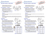
This guide provides instructions for an installer to set up and operate
any of the Extron MTP 15HD A transmitters and receivers.
PRE-PEAK
12V
.5A MAX
Installation
Turn off all MTPs and devices.
Turn the input and output devices off and unplug their power
cords. Verify that all MTPs are disconnected from the power
sources before proceeding.
1
MONITOR
2
3
OFF
12V
.5A MAX
5
RGB
6
Terminate and connect TP cables between units.
• Connect a TP cable between the Output connector (f) of the transmitter and the Input
connector (g) of the receiver. Terminate the cable ends identically with either standard as
shown in figure 3.
• For daisy-chaining, connect up to eight receivers using TP cables between the Buffered
Output connector (h) of a receiver and the Input connector (g) of a daisy-chained receiver.
8
10
9
Sleeve ( )
Figure 2. Stereo Audio Plug
Pins:
12345678
Insert Twisted
Pair Wires
ATTENTION:
Connect the sleeves to the ground (G). Connecting the sleeves
to a negative (–) terminal will damage the audio output circuits.
5 White-blue
White-blue
6 Orange
Green
7 White-brown
White-brown
8 Brown
Brown
Figure 3. TP Termination
No Ground Here
Tip
Sleeves
Tip
Do not tin the wires!
No Ground Here
Unbalanced Output
R
H SYNC +
V SYNC +
S-VIDEO
END UNIT
SPARE
L
Tip
Ring
Sleeves
Tip
Ring
MONO AUDIO
Terminate the power cable and ground the unit.
Blue
R
The receiver being configured is the last receiver in a daisy-chained system.
White-green
4 Blue
L
•
Set the End Unit switch Off (down) on the receiver being configured if there are one or
more receivers connected to the Buffered Output RJ-45 connector.
Orange
3 White-orange
MONO AUDIO
The receiver being configured is the only receiver connected
to the transmitter.
T568B
Wire Color
White-orange
NOTE: If you are using Enhanced Skew-Free™
A/V cable, use the TIA/EIA T568A standard only.
Configure the receiver DIP switches.
See figure 5 for DIP switch (located on the front panel of the receiver) layout and settings.
• H Sync + and V Sync + switches — Set these switches On (up) for positive sync or Off
(down) for negative sync.
• S-Video switch — Set this switch ON (up) to output chroma on pin 3 and luma on pin 2.
Set this switch OFF (down) to output chroma on pin 1 and luma on pin 2.
• End Unit switch — Set this switch On (up) if either of the following is true:
•
T568A
Pin Wire Color
1 White-green
2 Green
Connect the receiver outputs.
• Connect a VGA display to the Output connector (i)
• Connect a 3.5 mm, 5-pole captive screw audio connector into the Mono Audio
connector (j) for two mono audio outputs. Wire the connector as shown in figure 4.
ATTENTION:
7
1
Tip
Left (+)
Ring
Right (-)
3.
6.
MONO AUDIO
L
R
Figure 1. Transmitter and Receiver Rear Panels
Connect the transmitter inputs.
• Connect a VGA video source to the Input connector (b)
• Connect a VGA monitor to the Monitor connector (c)
• Connect a 3.5 mm stereo audio plug into the Audio connector (d).
Wire the plug as shown in figure 2.
5.
OUTPUTS
BUFFERED
OUTPUT
INPUT
OUTPUT
2.
4.
POWER
ON
INPUT
1.
MT P RL 15HD A
MTP T 15HD A
AUDIO
POWER
Balanced Output
Figure 4. Captive Screw
Connector
ON
1 2 3 4 5
Figure 5. DIP Switches
See “Power Supply Wiring” in the user guide before wiring.
POWER
12V
0.5A MAX
Smooth
Wire the 2-pole captive screw connectors as shown in figure 6. Plug them into the Power connectors (a)
of the MTPs. The LED indicator on each MTP should be on when receiving power.
Grounding guidelines:
Extron MTP 15HD A products can be adversely affected by electrostatic discharge (ESD) if they are not
grounded correctly.
To prevent malfunctions or product damage, an installer can correctly ground an Extron MTP 15HD A series
product by grounding the power input port. Insert one end of the grounding wire to the negative or ground pin
on the power input connector (see figure 6). Tie the other end of the wire to an earth ground.
A
Ridges
Rear
Panel
A
3/16"
(5 mm)
Max.
Tie
Wrap
SECTION A–A
Ridges
Power Supply
Output Cord
Earth
Ground
Figure 6. Power Wiring
and Grounding
If you have any questions about how to ground a product in a specific application, contact an Extron technical
support specialist.
1
MTP 15HD A • Setup Guide (Continued)
7.
Configure EDID
See the “EDID Minder” section for instructions on configuring EDID.
8.
Adjust level and peaking.
• Pre-Peak switch (transmitter) — View the image and set the Pre-Peaking switch (e).
Set this switch to On (up) to compensate for long cable runs of the entire system.
• Level control (receiver) — View the image and adjust the Level control (see figure 7).
Full counterclockwise is minimum level.
• Peaking control (receiver) — View the image and adjust the Peaking control (see figure 7).
Full counterclockwise is zero peaking.
9.
RGB
LEVEL
Figure 7. Level and Peaking
Adjust skew delay control (SEQ receivers).
Adjust the skew delay as follows (see figure 8):
a.
DELAY
Zero the skew delay for red, green, and blue by using a small screwdriver to press and hold the
Select button for 3 seconds. When the red, green, and blue LEDs all go out, release the Select button.
b. Use UTP cable test equipment or examine the displayed image to determine which video signal
(red, green, or blue) is shifted furthest to the left.
c.
PEAKING
RED
SELECT
GREEN
BLUE
Figure 8. Skew Delay Control
Select the furthest left video signal by using a small screwdriver to press and release the
Select button until the LED for the left-shifted color lights.
d. Slowly rotate the Delay knob clockwise until the selected color is converged.
e.
If the remaining colors are left shifted, repeat steps b through d.
10. Mount the MTPs.
If necessary, mount the MTPs. For mounting information, see the MTP 15HD A Series User Guide.
EDID
SELECT
50 Hz
ON
RECORD
60 Hz
1
2
SPARE
3
MTP SERIES
4
Figure 9. MTP Transmitter Front Panel
EDID Minder
To use factory-installed EDID information or the user-recorded EDID:
1.
If you have not already done so, connect the source device to the MTP 15HD transmitter.
Do not power on the source device at this time.
2.
Set the front panel DIP switch (c) to the required frequency (50 or 60 Hz).
3.
Set the rotary dial (d) to the required position (see the table to the right). Positions 1
through E are factory installed. Position 0 is for user-recorded EDID information. Position
F passes the EDID from the display connected to the Monitor loop-through port on the
transmitter back to the input.
To record EDID information from a specific monitor:
1.
Turn the EDID Select dial (d) to position 0.
NOTE:
2.
The frequency DIP switch position (c) has no effect in this mode.
Connect a display to the Monitor connector on the transmitter.
NOTE:
The MTP 15HD RS transmitter should be supplying the necessary
5 VDC to power on the display. However, to ensure that EDID is being
transmitted, power on the display.
3.
4.
2
Press and release the recessed Record button (b) to begin the recording process. The
Record LED (a) flashes red rapidly during recording, then returns to solid green after
recording is completed. At this time, the display can be disconnected. Connect the source
device to the input connector.
Rotary Switch
Position
Resolution
0
User-recorded EDID
1
800x600
2
1024x768 (default)
3
1280x720
4
1280x768
5
1280x800
6
1280x1024
7
1360x768
8
1366x768
9
1400x1050
A
1400x900
B
1600x1200
C
1680x1050
D
1920x1080
E
1920x1200
F
Local monitor pass-through
Power on or restart the source device.
© 2013 Extron Electronics — All rights reserved. All trademarks mentioned are the property of their respective owners. www.extron.com
68-2206-50
Rev. B
03 13