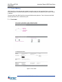
1
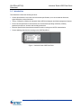
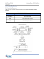
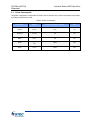
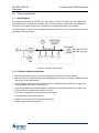
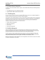
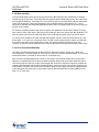
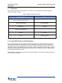
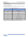
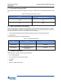
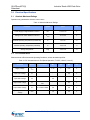
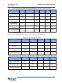
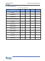
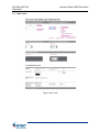
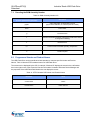
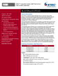
1GB to 8GB Industrial Grade USB Flash Drive SLUFDxxxU2TU(I) Capacity: 1GB - 8GB USB 2.0 Compliant LED activity indicator Customizable for logo/graphic design High Reliability: Guaranteed 2M Write Operations Advanced Wear-Leveling BCH ECC Engine corrects up to 12 bits/512 Bytes errors Automatic Bad Block Management Single Level Cell (SLC) NAND Flash Memory 10 Year Data Retention General Description STEC’s Industrial Grade USB Flash Drive (UFD) is more than just portable storage. Tailored for industrial applications that require high reliability and data throughput, it provides non-volatile, industrial grade solid-state storage in a thumb-drive package. In addition, labeling allows for lot traceability and complete info on the Bill of Materials. The Industrial Grade UFD is available in an ESD rated enclosure (with LED light indicator) for applications that require NEBS Level 3 compliancy. The ESD-rated enclosure has been tested for immunity from ESD for 8KV contact and 15KV air. STEC’s U2T, state-of-the-art, USB 2.0 flash memory controller is incorporated in the Industrial Grade UFD, providing high data integrity and endurance. The flash management software that is embedded in the controller emulates a hard disk, enabling read/write operations that are identical to a standard, sector-based hard disk. Sophisticated wear leveling algorithms ensures greater flash endurance, while automatic bad block management and a built-in ECC Engine guarantee the highest data reliability. Based on the BCH error correct algorithm, the ECC engine can correct up to 12-bit errors per 512 Bytes. High performance, high reliability and a controlled Bill-Of-Materials make the Industrial Grade UFD the product of choice in industrial applications, such as POS Workstations, Networking Equipment, automotive diagnostics and Industrial PCs. The UFD is fully customizable to add a company logo, graphic design, or text. In addition, STEC offers value-added services to OEM customers, such as pre-loaded content and controlled Bill Of Materials. Ordering Information: USB Flash Drive NEBS Level 3 compliant for ESD 8KV Contact, 15KV Air Lot Traceability Part Number Capacity SLUFD1GU2TU(I) 1 GBytes SLUFD2GU2TU(I) 2 GBytes SLUFD4GU2TU(I) 4 GBytes SLUFD8GU2TU(I) 8 GBytes Legend: Commercial and Industrial Operating Temperature RoHS-6 Compliant SLUFD = STEC standard USB Flash Drive part number prefix 1G/2G/4G/8G = 1GB / 2GB / 4GB / 8GB Capacity U2T = STEC U2 controller (2 U = RoHS-6 compliant Part numbers without (I) = Commercial temperature range (0ºC to 70ºC) I = Industrial temperature range (-40ºC to 85ºC) nd Generation) SLUFDxxxU2TU(I) Datasheet Industrial Grade USB Flash Drive Table of Contents General Description ................................................................................................................. 1 Ordering Information: USB Flash Drive ................................................................................. 1 1.0 Introduction....................................................................................................................... 3 2.0 Product Specifications ..................................................................................................... 4 2.1 2.2 2.3 2.4 2.5 Mechanical Dimensions................................................................................................................ 4 Pin Assignment and Description................................................................................................... 5 Performance ................................................................................................................................. 5 LED Functionality.......................................................................................................................... 5 Power Consumption ..................................................................................................................... 6 3.0 Theory of Operation ......................................................................................................... 7 3.1 Block Diagram .............................................................................................................................. 7 3.1.1 Controller Internal Components ................................................................................................ 7 3.1.2 Controller External Components ............................................................................................... 8 3.2 Flash Management ....................................................................................................................... 8 3.2.1 Bad Block Management ............................................................................................................ 8 3.2.2 Wear Leveling ........................................................................................................................... 9 3.2.3 Error Correction/Detection ........................................................................................................ 9 3.3 OS Support ................................................................................................................................. 10 3.3.1 Using USB Flash Drive with XP Embedded ............................................................................ 10 3.4 Unique Serial Number ................................................................................................................ 11 4.0 Environmental Specifications .........................................................................................12 4.1 4.2 4.3 4.4 4.5 4.6 Recommended Operating Conditions ........................................................................................ 12 Reliability .................................................................................................................................... 12 Shock, Vibration, and Humidity .................................................................................................. 12 Electrostatic Discharge (ESD) .................................................................................................... 13 Mean Time Between Failure (MTBF) ......................................................................................... 13 Standards Compliance ............................................................................................................... 13 5.0 Electrical Specifications .................................................................................................14 5.1 Absolute Maximum Ratings ........................................................................................................ 14 5.2 DC Characteristics...................................................................................................................... 14 5.3 AC Characteristics ...................................................................................................................... 15 6.0 SCSI Command List ........................................................................................................16 7.0 Product Marking ..............................................................................................................17 7.1 Front Label ................................................................................................................................. 17 7.2 Back Label .................................................................................................................................. 18 7.3 Decoding the BOM Assembly Number ....................................................................................... 19 8.0 Programmed Vendor and Product Names .....................................................................19 9.0 Contact Information.........................................................................................................20 9.1 STEC Worldwide Headquarters ................................................................................................. 20 9.2 STEC Worldwide Locations ........................................................................................................ 20 10.0 Revision History ..............................................................................................................21 61000-07007-105, June 2011 2 SLUFDxxxU2TU(I) Datasheet 1.0 Industrial Grade USB Flash Drive Introduction This datasheet includes the following sections: Product Specifications covers the most referenced specifications, such as mechanical dimension, signal description, and performance. Theory of Operation explains the Industrial Grade UFD block diagram and flash management features. Environmental Specifications characterizes the recommended operating conditions, reliability parameters and shock, vibration and humidity parameters. Electrical Specifications describes the absolute maximum ratings and AC/DC characteristics. Product Marking describes the marking on the USB Flash Drive. Figure 1: Industrial Grade USB Flash Drive 61000-07007-105, June 2011 3 SLUFDxxxU2TU(I) Datasheet 2.0 Product Specifications 2.1 Mechanical Dimensions Industrial Grade USB Flash Drive Table 1 and Figure 2 show the mechanical dimensions of the Industrial Grade UFD with ESD-Rated Enclosure. Table 1: Mechanical dimension Parameter ESD-rated enclosure Length with Cap 66.1 mm (2.602 in) Max Width 16.60 ± 0.20 mm (0.654 ± 0.008 in) Height 7.02 ± 0.20mm (0.276 ± 0.008 in) Units: mm (in) Figure 2: Mechanical dimensions-UFD ESD-Rated enclosure 61000-07007-105, June 2011 4 SLUFDxxxU2TU(I) Datasheet 2.2 Industrial Grade USB Flash Drive Pin Assignment and Description Table 2: Pin Assignment and Description 2.3 Pin Number Signal Name Type Description 1 VBUS Power Bus voltage supply 2 D- I/O Data line – 3 D+ I/O Data line + 4 GND Ground Ground Performance The Industrial Grade UFD is USB 2.0 high-speed (480Mb/sec) and USB 1.1 full-speed (12Mb/sec) compliant. Measured performance for high-speed can be found in Table 3. Table 3: Read/Write Performance 2.4 Parameter Value Sustained Read up to 30 MB/sec Sustained Write up to 20 MB/sec LED Functionality The Industrial Grade UFD with standard enclosure incorporates a LED activity indicator that functions as described below: LED flashing: Industrial Grade UFD is transmitting/receiving data or is identification process Default LED colors: Blue 61000-07007-105, June 2011 5 SLUFDxxxU2TU(I) Datasheet 2.5 Industrial Grade USB Flash Drive Power Consumption The power consumption currents listed in Table 4 are for reference only. Power consumption may change according to flash memory used. Table 4: Power Consumption Power State Symbol Power Consumption (Typical) Unit Normal INORMAL 70.6 mA Suspend ISUSPEND 0.8 mA Sleep ISLEEP 0.8 mA Read IREAD 108.3 mA Write IWRITE 160.9 mA 61000-07007-105, June 2011 6 SLUFDxxxU2TU(I) Datasheet 3.0 Theory of Operation 3.1 Block Diagram Industrial Grade USB Flash Drive The Industrial Grade UFD uses STEC’s U2T, state-of-the art, USB 2.0 controller, and is combined with SLC NAND Flash for optimal device reliability. The controller’s firmware supports the latest NAND flash technology from multiple vendors, and is optimized for the highest performance and reliability. The USB controller consists of the functional blocks as shown in Figure 3. The blocks are described in the paragraphs following the figure. Figure 3: Controller block diagram 3.1.1 Controller Internal Components Microcontroller which serves as the hardware backbone for the flash controller algorithm. USB 2.0 Interface Controller with high speed (480 Mbps) device function. This block interfaces with the host system via the USB interface. Flash Interface Controller that serves as the interface to the NAND flash components. It supports all the major NAND flash memory manufacturers. Flash Storage Management Algorithm Block is responsible for the flash management, including wear leveling, bad block management, and Error Correction. ECC block is responsible for on-the-fly error and correction. Sector Buffer for optimized performance. SRAM for running controller firmware fast and efficient. ROM for storing controllers boot code. 61000-07007-105, June 2011 7 SLUFDxxxU2TU(I) Datasheet Industrial Grade USB Flash Drive 3.1.2 Controller External Components In addition to the functional blocks shown in Figure 3, the Industrial Grade UFD has the following external components: SLC NAND Flash for the most reliable data storage. Crystal Oscillator 12Mhz, as the main clock source. 3.2 Flash Management Since the Industrial Grade UFD provides a standard USB interface to the host, no software integration is required, providing the shortest time-to-market for design engineers. The firmware of the embedded USB 2.0 controller contains STEC’s advanced flash memory management algorithms to ensure the most optimum device performance, reliability and endurance. It was designed to maximize the benefits of flash memory, while at the same time overcoming inherent NAND flash limitations. Implemented in firmware are the below features: Flash file system management Bad-block management Wear-leveling Performance optimization 3.2.1 Bad Block Management Inherent to NAND flash technology are areas (blocks) on the media that cannot be used for storage because of their high error rate. These so-called “bad blocks” are already identified by the flash vendor during manufacturing, but can also be accumulated over time during device operation. The U2T controller contains a table that lists all the bad blocks on the device (Bad Block Table), and automatically maps out these blocks upon system initialization. During device operation it ensures that newly accumulated bad blocks are also mapped out and added to the Bad Block Table. Bad block management is 100% transparent to the host application, which will not be aware of the location or existence of bad blocks on the media. 61000-07007-105, June 2011 8 SLUFDxxxU2TU(I) Datasheet Industrial Grade USB Flash Drive 3.2.2 Wear Leveling The SLC NAND flash devices that are being used in the USB Flash Drive are guaranteed for 100,000 Write/Erase cycles per block. This means that after approximately 100,000 erase cycles, the erase block has a higher probability for errors than the error rate that is typical to the flash. While 100,000 write/erase cycles may be good for consumer data storage, such as digital cameras, MP3 players, etc., it is not sufficient for industrial and embedded applications where data is constantly written to the device and long product life is required. For example, operating systems that use a file system, will update the File Allocation Table (FAT) every time a write is done to the device. Without any wear leveling in place, the area on the flash where the FAT table is located would wear out faster than other areas, reducing the lifetime of the entire flash device. To overcome this limitation, the flash management algorithm needs to make sure that each block in the device ages, i.e. is “worn out”, at the same rate. The built-in wear leveling scheme makes sure that with every write to the flash, the youngest block is used. This ensures that the full flash media is used uniformly, so that one area of the flash will not reach the endurance limits prematurely before other areas. 3.2.3 Error Correction/Detection The USB 2.0 controller implements an advanced Error Correction scheme, based on the BHC error correct algorithm. The ECC engine can correct up to 12-bits per 512 Bytes (symbol based). To ensure the fastest performance, correction is done on-the-fly, in hardware only. Each time the host application writes a sector of 512 bytes to the Industrial Grade UFD, a unique ECC signature is created by the ECC engine and written together with the data to the flash. When the data is read back by the host, the ECC engine creates again the unique ECC signature. It will then compare the original written signature with the newly created signature, and sets an error flag if the two signatures are not the same. Correction of the data is done on-the-fly when the error flag is set, and the data presented to the host will be the same as the original written data an Uncorrectable Bit Error Rate (UBER) of less 14 than 1 in 10 bits, read. 61000-07007-105, June 2011 9 SLUFDxxxU2TU(I) Datasheet 3.3 Industrial Grade USB Flash Drive OS Support The Industrial Grade UFD is recognized as a removable drive and supports the following Operating Systems, as listed in Table 5. Table 5: Supported Operating Systems Operating System Version Windows 98/2000/XP/Vista/Windows 7 Windows XP Embedded Service Pack 2007 Windows CE 4.2 and 5.0 Windows for POS (WEPOS) VxWorks 6.1 and up Linux Kernel 2.4 and up Note: Windows 98 requires driver. 3.3.1 Using USB Flash Drive with XP Embedded When using USB Flash Disk Drive with Windows XP Embedded, it is recommended that the Enhanced Write Filter (EWF) feature is implemented. The EWF intercepts calls at the sector level, and thereby eliminates many file system updates/writes to the flash. Windows XP Embedded Service Pack 2 Feature Pack 2007 introduced an additional write protect feature, called File Based Write Filter (FBWF). The new FBWF function write-protects embedded devices at the file level, in contrast to the EWF, which has been protecting devices at the sector level. FBWF and EWF, combined with the built-in wear leveling algorithm, ensure that the maximum life span of the flash device is achieved. 61000-07007-105, June 2011 10 SLUFDxxxU2TU(I) Datasheet 3.4 Industrial Grade USB Flash Drive Unique Serial Number During manufacturing stage, a unique serial number is written to the USB Flash Disk that includes a date code related to the time of manufacturing. The serial number uses the following format: [AA][B][C][DD][EE][FFFF][GGGG] Table 6 below describes the parameters of the serial number. Table 6: Unique Serial Number format Symbol Parameter AA STEC Reserved (86h) B Year (hex) C Month (hex) DD Day (hex) EE Production PC Number (hex) FFFF Last 2 Bytes of MAC Address GGGG Serial Number, Incremental (hex) The Serial Number can be obtained through Windows Device Manager or Linux lsusb utility. 61000-07007-105, June 2011 11 SLUFDxxxU2TU(I) Datasheet Industrial Grade USB Flash Drive 4.0 Environmental Specifications 4.1 Recommended Operating Conditions Table 7: Recommended Operating Conditions Parameter Symbol Min Typ Max Unit Commercial Operating Temperature TA 0 25 70 C Industrial Operating Temperature TA -40 - 85 C Bus Voltage (5V) VBUS(5V) 4.75 5.0 5.25 V 4.2 Reliability Table 8: Reliability Parameter Value Endurance 2M write operations Uncorrectable Bit Error Rate (UBER) 4.3 <1 uncorrectable error per 10 14 bits read Data retention 10 years Durability 1500 insertions/removals Shock, Vibration, and Humidity Table 9: Shock, Vibration & Humidity Parameter Value Shock 1500G Peak, 0.5m pulse duration, 5 pulses, 6 axes (per JESD22-B110) Vibration 20G Peak, 20-2000 Hz, 4 cycles per direction (X, Y and Z) (per JESD22-B103) Humidity 85°C, 85% RH, Vmax for 500 hrs (per JESD22-A101) 61000-07007-105, June 2011 12 SLUFDxxxU2TU(I) Datasheet 4.4 Industrial Grade USB Flash Drive Electrostatic Discharge (ESD) The Industrial Grade UFD has been tested for immunity from ESD under the conditions described in Table 10. Table 10: Electrostatic Discharge for UFD 4.5 ESD Type ESD Rated Enclosure (Maximum Discharge) Contact 8KV Air 15KV Mean Time Between Failure (MTBF) STEC estimates Mean Time Between Failure (MTBF), using a prediction methodology based on reliability data for the individual components in the USB Flash Drive. Table 11 summarizes the prediction results for the USB Flash Disk Drive, based on the following two methodologies: Telcordia Special Report SR-332, Reliability Prediction Procedure for Electronic Equipment. MIL-HNBK-217 The analysis was performed using Relex Software. Table 11: USB Flash Drive MTBF 4.6 Product Condition MTBF (hours) SLUFD4GU2TU Telcordia SR-332, GB, 25°C MIL-HNBK-217 >4,000,000 SLUFD8GU2TU Telcordia SR-332, GB, 25°C MIL-HNBK-217 >4,000,000 Standards Compliance USB Flash Drive complies with the following standards: CE - EN 55022/55024 FCC - Class B for Information Technology UL 60950 RoHS-6 USB 2.0 – Mass Storage Class 61000-07007-105, June 2011 13 SLUFDxxxU2TU(I) Datasheet Industrial Grade USB Flash Drive 5.0 Electrical Specifications 5.1 Absolute Maximum Ratings Operation not guaranteed at extreme corner cases. Table 12: Absolute Maximum Ratings Parameter Symbol Value Unit Power Supply Voltage Relative to Ground VBUS -0.3 to 5.5V V Voltage on D+ and D- Relative to Ground VDATA -0.3 to 3.6 V Ambient Operating Temperature (Commercial) TA 0 to +70 C Ambient Operating Temperature (Industrial) TA -40 to +85 C Storage Temperature Tstg -40 to +85 C 5.2 DC Characteristics Measurements at Recommended Operating Conditions, unless otherwise specified. Table 13: DC Characteristics for Full-Speed Operation (TA=25ºC, Vdd=5V, Vss=0V) Parameter Symbol Supply Voltage Test conditions Min Typ Max Unit VBUS 4.75 5 5.25 V Input LOW Voltage VIL - - 0.8 V Input HIGH Voltage VIH 2.0 - - V Output LOW Voltage VOL RL of 1.5kΩ to 3.6V - - 0.3 V Output HIGH Voltage VOH RL of 15kΩ to GND 2.8 - 3.6 V Output Signal Crossover Voltage VCRS 1.3 - 2.0 V 61000-07007-105, June 2011 14 SLUFDxxxU2TU(I) Datasheet Industrial Grade USB Flash Drive Table 14: DC Characteristics for High-Speed Operation (TA=25ºC, Vdd=5V, Vss=0V) Min Typ Max Unit VBUS 4.75 5 5.25 V High Speed Idle Level VHSOI -10 - 10 mV High Speed Data Signaling High VHSOH 360 - 440 mV High Speed Data Signaling Low VHSOL -10 - 10 mV Chirp J Level (differential Voltage) VCHIRPJ 0.7 - 1.1 V Chirp K Level (differential Voltage) VCHIRPK -0.9 - -0.5 mV 5.3 Parameter Symbol Supply Voltage Test conditions AC Characteristics Measurements at Recommended Operating Conditions, unless otherwise specified. Table 15: AC Characteristics Full Speed Parameter Symbol Min Typ Max Unit Rise Time TFR 4 - 20 ns Fall Time TFF 4 - 20 ns Differential Rise and Fall Time Matching TFRFM 90 111.11 % Driver Output Resistance ZDRV 28 44 Ω - Table 16: AC Characteristics High Speed Parameter Symbol Min Typ Max Unit Rise Time (10%~90%) THSR 500 - - ps Fall Time (10%~90%) THSF 500 - - ps Driver Output Resistance ZHSDRV 40.5 - 49.5 Ω 61000-07007-105, June 2011 15 SLUFDxxxU2TU(I) Datasheet 6.0 Industrial Grade USB Flash Drive SCSI Command List Table 17: SCSI Command List Command List OpCode RBC SPC-2 SPC-3 INQUIRY 12h √ √ √ MODESENSE(6) 1Ah √ √ √ MODESENSE(10) 5Ah - √ √ PREVENT/ALLOW MEDIUM REMOVAL 1Eh √ √ √ READ(10) 28h √ - - READ CAPACITY 25h √ - - REQUEST SENSE 03h - √ √ START STOP UNIT 1Bh √ - - TEST UNIT READY 00h √ √ √ WRITE(10) 2Ah √ - - VERIFY(10) 2Fh √ - - SYNC CACHE 35h √ - - 61000-07007-105, June 2011 16 SLUFDxxxU2TU(I) Datasheet 7.0 Industrial Grade USB Flash Drive Product Marking USB Flash Drive will be shipped with standards compliance logos on the front label (Figure 4) and the manufacturing info on the back label (Figure 5), thereby providing lot traceability and full access to the Bill of Material. The back label of the USB Flash Drive shows the BOM Assembly Number. Table 18 decodes the BOM Assembly Number into the manufacturing info. 7.1 Front Label Figure 4: Front Label 61000-07007-105, June 2011 17 SLUFDxxxU2TU(I) Datasheet 7.2 Industrial Grade USB Flash Drive Back Label Figure 5: Back Label 61000-07007-105, June 2011 18 SLUFDxxxU2TU(I) Datasheet 7.3 Industrial Grade USB Flash Drive Decoding the BOM Assembly Number Table 18: BOM Assembly Number info 8.0 BOM Assembly Number (Format: ppp00-0xxxx-yyzT(C/I)U) Description ppp00 STEC designation for OEM Flash products (ppp is 940 for standard, or customer prefix for custom) 0xxxx PCB number yy Product Revision z Capacity Designator (Randomly assigned per PCB number based on designator availability) T Model Revision C, I Commercial and Industrial Operating Temperature U RoHS Compliant Programmed Vendor and Product Names The USB Flash Drive can be manufactured with standard or customer-specific Vendor and Product Names. Table 19 lists the STEC standard names for USB Flash Drive. The names can be displayed by the OS, for example, Windows XP displays the names in the notifications area in the right corner of the screen the first time the module is installed. Windows Device Manager and the properties of the USB Flash Disk Module also can display the names Table 19: STEC Standard USB Vendor and Product Names Parameter Value Vendor Name “STEC” Product Name “STEC USB 2.0” 61000-07007-105, June 2011 19 SLUFDxxxU2TU(I) Datasheet Industrial Grade USB Flash Drive 9.0 Contact Information 9.1 STEC Worldwide Headquarters STEC INC 3001 Daimler Street General Support: 1-949-476-1180 Santa Ana, California 92705 Fax Number: 1-949-476-1209 United States of America (USA) E-mail: [email protected] 9.2 STEC Worldwide Locations STEC ITALY S. R. L. STEC TAIWAN STEC JAPAN G.K. Via del Caravaggio, 3 RM1101, 11F, No. 495 Shinyurigaoka-City Building 4-402 20111 Milano Guang-Fu S. Road 1-1-1, Manpukuji, Aso-ku, Kawaski-shi Italy Taipei Kanagawa-ken 215-0004 Taiwan Japan Phone: +39 02 497 56 213 Phone: +886 2 8780 8000 Ext. 1101 Phone: +81 44-959-2883 Fax: +886 2 8725 7711 Fax: +81 44-959-2887 STEC MALAYSIA STEC CHINA STEC Technology Sdn RM1805, 18F Bund Centre Plot 107 Bayan Lepas Industrial Park 222 Yan An Road East Phase 4 HuangPu District Shanghai 200002 11900 Penang, Malaysia P.R. China Phone: Phone: +86 21 6132 3892 Ext. 629 Fax: +86 21 6335 1336 +60 (4) 8887888 61000-07007-105, June 2011 20 SLUFDxxxU2TU(I) Datasheet Industrial Grade USB Flash Drive 10.0 Revision History Revision Date Description -101 02/14/2011 Preliminary release. -102 02/23/2011 Label on photo of UFD updated. Extended changed to Industrial.Temperature. “T” designator added to BOM Assembly Number. -103 04/08/2011 UBER, Endurance, and ECC Engine corrected (paper error only). -104 04/26/2011 Photo edited to increased dpi. Preliminary notice removed. -105 06/07/2011 Logo updated. 61000-07007-105, June 2011 21 SLUFDxxxU2TU(I) Datasheet Industrial Grade USB Flash Drive DISCLAIMER OF LIABILITY STEC™ Inc. reserves the right to make changes to specifications and product descriptions such as but not limited to numbers, parameters and other technical information contained herein without notice. Please contact the STEC™ Inc. sales office to obtain the latest specifications. STEC™ Inc. grants no warranty with respect to this datasheet, neither explicit or implied, and is not liable for direct or indirect damages. Some states do not grant the exclusion of incidental damages and as such this statement may not be valid in such states. The provisions of the datasheet do not convey to the purchaser of the device any license under any patent rights or other intellectual property rights of STEC Inc. or others. EXPORT ADMINISTRATION REGULATIONS The information provided may be subject to United States Export Controls. Such information should not be downloaded or exported (i), into (or to a national or resident of) Cuba, Iraq, Libya, North Korea, Iran, Syria, or any other country to which the United States has embargoed goods; or given to (ii), anyone on the United States Treasury Department’s list of Specially Designated Nationals or the U.S. Commerce Departments’s Table of Deny Orders. By using the information, you represent and warrant that you are not located in, under the control of, or a national or resident of any such country or on any such list. COPYRIGHT NOTICE Copyright © 2011 by STEC™ Inc. All rights reserved. Information contained in this document, including but not limited to any instructions, descriptions and product specifications, is considered proprietary and confidential to STEC™, Inc. and shall not be modified, used, copied, reproduced or disclosed in whole or in part, in any form or by any means, electronic or mechanical, for any purpose, without the written consent of STEC™ Inc 61000-07007-105, June 2011 22