1
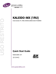
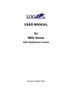
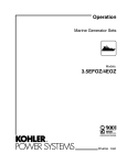
Service Parts
Commercial Mobile Generator Sets
Models:
7ER
6EFR
Specification Series 199
TP-6036 6/99
Table of Contents
Description
Page
Introduction . . . . . . . . . . . . . . . . . . . . . . . . . . . . . . . . . . . 1
Numbering System Significance . . . . . . . . . . . . . . . . . 1
Illustrations . . . . . . . . . . . . . . . . . . . . . . . . . . . . . . . . . . . 1
How to Find Part Numbers . . . . . . . . . . . . . . . . . . . . . . 1
Hardware References . . . . . . . . . . . . . . . . . . . . . . . . . . 1
Specification Number Index . . . . . . . . . . . . . . . . . . . . . 2
Group 1: Cylinder and Crankcase . . . . . . . . . . . . . . . 3
Group 2: Piston and Crankshaft . . . . . . . . . . . . . . . . . 4
Group 3: Valves and Camshaft . . . . . . . . . . . . . . . . . 5
Group 4: Lubrication and Oil Filter . . . . . . . . . . . . . . . 5
Group 5: Ignition . . . . . . . . . . . . . . . . . . . . . . . . . . . . . . 6
Group 6: Governor . . . . . . . . . . . . . . . . . . . . . . . . . . . . 7
Group 7: Carburetor . . . . . . . . . . . . . . . . . . . . . . . . . . . 8
Group 8: Air Filter and Muffler . . . . . . . . . . . . . . . . . 10
Group 9: Starter . . . . . . . . . . . . . . . . . . . . . . . . . . . . . 11
Group 10: Engine Cooling . . . . . . . . . . . . . . . . . . . . . 12
Description
Page
Group 103: Fuel System . . . . . . . . . . . . . . . . . . . . . . 13
Group 105: Engine . . . . . . . . . . . . . . . . . . . . . . . . . . . 14
Group 107: Nameplate and Decals . . . . . . . . . . . . . 16
Group 109: Skid and Plant Mounting . . . . . . . . . . . 16
Group 116: Exhaust . . . . . . . . . . . . . . . . . . . . . . . . . . 17
Group 201: Generator and Mounting . . . . . . . . . . . 18
Group 301: Controller and Mounting . . . . . . . . . . . . 20
Group 701: Literature . . . . . . . . . . . . . . . . . . . . . . . . . 22
Accessories (and Kit Sections) . . . . . . . . . . . . . . . . . 23
Appendix A. Glossary of Abbreviations . . . . . . . . A-1
Appendix B. Common Hardware
Application Guidelines . . . . . . . . . . . . . . . . . . . . A-3
Appendix C. General Torque Specifications . . . . . A-4
Appendix D. Common Hardware Identification . . A-5
Appendix E. Common Hardware List . . . . . . . . . . A-6
Introduction
This manual lists service replacement parts for
7ER/6EFR generator sets.
At the time of print this manual applied to the generator
set specification (spec) numbers listed in the
Specification Number Index. On occasion this manual
may apply to specs not listed in the Specification
Number Index.
Information in this publication represents data available
at the time of print. Kohler Co. reserves the right to
change this publication and the products represented
without notice and without any obligation or liability
whatsoever.
This manual includes the following main sections:
Table of Contents. Lists the sections of the manual.
Introduction (and other information sections).
Contains introductory material about part numbers,
illustrations, and hardware.
Index. Lists the generator set specs and groups.
Group Parts Lists. List the part numbers of parts in the
groups.
Kit Sections. List modules and accessories and their
parts.
Appendices.
Include Abbreviations, Common
Hardware Application Guidelines, General Torque
Specifications, Common Hardware Identification, and
Common Hardware List.
x:in:004:002
Numbering System Significance
This manual uses the following numbering systems:
Specification Number. A six-digit number with a PAprefix. The Specification Number Index does not show
the prefix. Spec numbers break down into groups.
Group Number. A unique number representing a parts
group needed to assemble a generator set function. For
example, Group 101 is the Air Intake group.
Variation or Module Number. A group might have
several variations. Each variation performs the same
function with different parts lists. For example, a 50 Hz
generator alternator and 60 Hz generator alternator
both perform the same function, however, with different
parts. Each difference requires a group variation or
module number.
Part Number. The part number identifies an individual
assembly, subassembly, component, or accessory kit.
x:in:004:003
Illustrations
Illustrations (or exploded-view drawings) best
representing the widest range of variations accompany
most groups in this manual. Illustrations do not depict all
details and may not show all parts. Do not use
illustrations for assembly or disassembly instructions.
x:in:004:004
How to Find Part Numbers
Use the following steps to locate a service replacement
part.
1. Locate the generator set nameplate to identify the
generator set spec number.
2. Locate a second generator set nameplate listing
accessories to identify installed modules. On
some models the accessory nameplate is mounted
inside the generator junction box.
3. Turn to the Specification Number Index. The
first column lists the generator set spec numbers.
The headings identify the groups of parts that make
up the generator set.
4. Identify the group most likely to include the
service part number.
5. Find the group variation number at the
intersection of the spec number row and the group
column. Note the variation number.
6. Page forward to locate the group identified in
step 4 or find the appropriate page in the Table of
Contents.
7. Find the part on the illustration and note the item
number of the part or find the part description in
the parts list.
8. Select the part number that corresponds to
your group variation. The first column lists the
illustration item number.
Find the variation
identified in the Specification Number Index or the
module number found on the generator set
nameplate in the appropriate column on the right
side of the parts list table. Find the quantity used at
the intersection of the item number row and the
variation column. A blank space at the intersection
means the variation/module does not use that part
number.
x:in:004:005
Hardware References
Many common hardware items do not appear in parts
manuals or will appear as common hardware entries. A
common hardware entry lists the size of the hardware.
For example, an item that appears as “Hardware,
3/8-16” in the text means that the piece is 3/8-16 size.
Obtain common hardware locally or, if contacting the
factory, use the Common Hardware List in the appendix
to identify the common hardware part number and
specifications. See Common Hardware Application
Guidelines in the appendix for mating hardware
instructions.
Some hardware items require a specific size or some
other characteristic. In that case, use the part number
listed in the text.
When replacing hardware, do not substitute inferior
grade hardware. Replacement hardware grade should
be equal to or better than the grade of the
manufacturer’s original hardware. Use the Common
Hardware List in the appendix to identify the common
hardware hardness.
x:in:004:006
TP-6036 6/99
1
Specification Number Index
GROUP TITLE
AND
NUMBER
GROUP NO.
1
2
3
4
5
6
7
8
9
10
VARIATION NUMBER
19950
1
1
1
1
1
1
1
1
1
1
19951
1
1
1
1
1
1
1
1
1
1
19954
1
1
1
1
1
1
1
1
1
1
19955
1
1
1
1
1
1
1
1
1
1
101
103
104
105
107
109
116
201
301
701
GROUP TITLE
AND
NUMBER
GROUP NO.
VARIATION NUMBER
SPEC NO.
2
19950
—
2
—
3
2
2
2
2
5
3
19951
—
2
—
3
2
2
2
3
5
3
19954
—
2
—
4
2
2
2
2
8
3
19955
—
2
—
4
2
2
2
3
8
3
TP-6036 6/99
Group 1: Cylinder and Crankcase
4
22
5
6
6
24
26
11
25
22
27
7
24
23
2
3
1
1
19
30
17
8
23
17
13
21
15
18
10
20
16
16
14
29
29
9
12
17
28
5987_1
Item
1
2
3
4
5
6
7
8
9
10
11
12
13
14
15
16
17
18
19
20
21
22
23
24
25
26
27
28
29
30
TP-6036 6/99
Part No.
359701
359981
359982
359704
359705
359706
359707
359708
359709
359710
359711
359712
359714
359715
359716
359719
359720
359721
359722
359723
359724
359725
359726
359727
359728
359729
359730
359731
359732
359717
Description
Qty.
Var.
1
Head Gasket
Complete Cylinder Head
Complete Cylinder Head
Rocker Case
Rocker Case
Rocker Case Gasket
Gasket
Crankcase Cover Gasket
Plate
Plate
Cover
Valve
Crankcase Cover
Complete Crankcase
Joint
Screw
Pin
Oil Seal
Oil Seal
Oil Seal
Plug
Collar
Bolt
Clamp
Tube
Flanged Bolt
Flanged Bolt
Flanged Bolt
Flanged Bolt
Stud
2
1
1
1
1
2
1
1
1
1
1
1
1
1
1
2
6
1
1
1
2
8
10
2
1
8
4
3
3
4
3
Group 2: Piston and Crankshaft
3
1
3
4
7
1
8
5
2
6
7
8
9
4
5987_2
Item
1
1
1
2
3
3
3
4
5
6
7
8
9
Part No.
359734
359739
359740
359735
359736
359737
359738
359741
359742
359743
359746
359748
359749
Description
Qty.
Var.
1
Piston
Piston, 0.25 OS
Piston, 0.50 OS
Piston Pin
Piston Ring Set
Piston Ring Set, 0.025 OS
Piston Ring Set, 0.50 OS
Connecting Rod Assembly
Crankshaft Assembly
Gear Spur
Snap Ring
Connecting Rod Bolt
Dowel Pin
2
AR
AR
2
2
AR
AR
2
1
1
4
4
1
AR As Required
4
TP-6036 6/99
Group 3: Valves and
Camshaft
12
14 15
11
Group 4: Lubrication and
Oil Filter
9
3
9
6
8
5
13
1
4
15
12
11
4
5
3
9
13
8
14
13
7
11
2
15
6
18
1
14
7
5
9
10
12
13
8
6
3
12
14
7
8
3
3
15
4
7
10
7
8
9
4
2
13
11
12
6
16
2
4
6
17
1
14
11
12
5987_4
5987_3
Item
1
2
3
4
5
6
7
8
9
10
11
12
13
14
15
Part No.
359983
359984
359985
359753
359754
359755
359756
359757
359986
359759
359760
359761
359762
359763
359987
TP-6036 6/99
Description
Intake Valve
Exhaust Valve
Valve Spring Retainer
Rocker Arm
Rocker Shaft
Tappet
Push Rod
Spring Seat
Engine Valve Spring
Complete Camshaft
Screw
Nut
Oil Seal
Circlip
Collet
Qty.
Var.
1
2
2
4
4
2
4
4
4
4
1
4
4
4
4
8
Item
1
2
3
4
5
6
7
8
9
10
11
12
13
14
15
16
17
18
Part No.
359764
359765
359766
359767
359773
359768
359769
359770
359771
359772
359774
359775
359902
359776
359777
359778
359779
359780
Description
Drain Plug Gasket
Oil Pump Shaft
Plate
Cover
Oil Gauge
Oil Fill Cap
Oil Pump Rotor (in)
Oil Pump Rotor (out)
Oil Filter
Oil Filter
Gear Spur
Pin
Ring, 0.20 mm
Drain Plug
Spring
Flanged Bolt
Pan Screw
Steel Ball
Qty.
Var.
1
1
1
1
1
1
1
1
1
1
1
1
2
1
1
1
3
2
1
5
Group 5: Ignition
12
19
19
22
1
5
4
5
23
6
29
16
15
14
23
13
27
21
25
10
26
11
9
28
7
8
3
24
20
18
17
24
2
5987_5
Item
1
2
3
4
5
6
7
8
9
10
11
12
13
14
15
6
Part No.
359781
359782
359783
359784
359785
359786
359787
359788
359903
359904
359789
359790
359791
359792
359807
Description
Gasket
Voltage Regulator
Igniter
Ignition Coil
Spark Plug Cap
Flywheel Assembly
Harness
Harness
Harness
Harness
Oil Pressure Switch
Temperature Switch
Pulsing Coil
Charging Coil
Hex Nut
Qty.
Var.
1
1
1
1
2
2
1
1
1
1
1
1
1
1
1
1
Item
16
17
18
19
20
21
22
23
24
25
26
27
28
29
Part No.
359793
359794
359795
359979
359797
359798
359799
359800
359801
359803
359804
359805
359806
359808
Description
Qty.
Var.
1
Washer
Clamp
Tube
Spark Plug
Band
Clamp
Clamp
Flanged Bolt
Flanged Bolt
Pan Screw
Pan Screw
Pan Screw
Pan Screw
Woodruff Key
1
2
2
2
3
1
2
4
4
1
4
4
1
1
TP-6036 6/99
Group 6: Governor
11
22
See groups 103 and 105 for
additional fuel system parts.
20
12
9
13
16
2
5
13
18
19
21
17
1
10
3
23
15
7
8
6
14
4
5987_6
Item
1
2
3
4
5
6
7
8
9
10
11
12
13
14
15
16
17
18
19
20
21
22
23
TP-6036 6/99
Part No.
359809
359810
359813
359814
359815
359816
359988
359818
359819
359820
359821
359822
359823
359905
359825
359826
359832
359833
359989
359835
359836
359837
359838
Description
Bracket
Lever
Link
Pivot Arm
Governor Spring
Sleeve
Governor Arm
Governor Assembly
Control Panel
Bolt
Screw
Nut
Washer
Spacer
Spring
Collar
Washer
Stud
Bolt
Bolt
Hex Nut
Hex Nut
Washer
Qty.
Var.
1
1
1
1
1
1
1
1
1
1
1
2
1
3
1
1
1
1
1
1
2
1
2
1
7
Group 7: Carburetor
9
24
55
39
34
8
46
18
43
23
22
33
19
20
60
13
26
32
61
3
50
12
44
56
16
48
10
40
44
37
51
36
17
27
40
49
58
28
25
35
57
21
4
15
1
5
58
41
14
38
29
45
54
6
47
11
31
52
30
42
2
7
53
59
6036_7
8
TP-6036 6/99
Group 7: Carburetor
Item
1
2
3
4
5
6
7
8
9
10
11
12
13
14
15
17
16
18
19
20
21
22
23
24
25
26
27
28
29
30
Part No.
359839
359840
359841
359842
359843
359844
359845
359846
GM10704
359848
359849
359850
GM10705
359852
359853
359854
GM10706
359856
359857
359858
GM10707
GM10708
359861
GM10709
359862
359907
359863
GM10710
359865
359866
TP-6036 6/99
Description
Gasket
Gasket
Air Filter Gasket
Carburetor Gasket
Intake Pipe Gasket
Intake Manifold Gasket
Intake Manifold Gasket
Plate
Carburetor Assembly
Pilot Air Screw
Float Chamber
Throttle Stop Screw
Throttle Valve
Float Valve
Float
Air Jet 1.2
Air Jet 1.0
Gasket
Carburetor Choke Shaft
Carburetor Shaft
Intake Pipe
Intake Pipe
Choke Valve
Choke Link
Solenoid
Wire Lead
Limiter
Main Nozzle
Main Jet Holder
Intake Manifold
Qty.
Var.
1
1
1
1
1
1
1
1
1
1
1
1
1
1
1
1
1
1
1
1
1
1
1
1
1
1
1
1
1
1
1
Item
31
32
33
34
35
36
37
38
39
40
41
42
43
44
45
46
47
48
49
50
51
52
53
54
55
56
57
58
59
60
61
Part No.
359867
359868
359869
359870
359871
359872
359873
359874
359875
359794
359876
359877
359878
359795
GM10711
GM10712
359911
359881
359882
359883
359884
359885
359912
359914
GM10713
359801
359889
359889
359890
359891
359915
Description
Qty.
Var.
1
Screw
Screw
Screw
Screw
Washer
Collar
Collar
Snap Ring
Clamp
Clamp
Pin
O-ring
O-ring
Tube
Main Jet
Pilot Jet
Plug
Spring
Spring
Seal
Seal
Spring
Bolt
Clamp
Tube
Flanged Bolt
Flanged Bolt
Flanged Bolt
Flanged Bolt
Flanged Bolt
Screw
1
2
2
1
1
1
1
1
1
2
1
1
1
1
1
1
1
1
1
1
1
1
1
1
1
1
2
5
3
2
1
9
Group 8: Air Filter and Muffler
7
10
11
2
8
3
4
5
6
12
1
13 14
Item
1
2
3
4
5
6
7
8
9
10
11
12
13
14
10
Part No.
359892
359893
359894
359895
359896
359897
359898
359899
359900
359901
GM10714
GM10715
GM10716
GM10717
Description
Air Filter Case
Air Filter Case
Air Filter Element
Air Filter Element
Bracket
Muffler Gasket
Intake Pipe
Complete Muffler
Collar
Bolt
Clamp
Bolt
Hex Nut
Spring Washer
9
6036_8
Qty.
Var.
1
1
1
1
1
1
2
1
1
6
2
1
6
5
5
TP-6036 6/99
Group 9: Starter
11
19
18
15
13
17
3
4
20
1
12
21
6
16
2
9
5
7
9
8
10
14
6036_9
Item
1
2
3
4
5
6
7
8
9
10
Part No.
GM10718
GM10719
GM10720
GM10721
GM10722
GM10723
GM10724
GM10725
GM10726
GM10727
TP-6036 6/99
Description
Clutch Assembly
Brush Holder
Shift Lever
Cover
Insulator
Cover Assembly
Cover Assembly
Brush
Brush Spring
Armature
Qty.
Var.
1
1
1
1
1
1
1
1
4
4
1
Item
11
12
13
14
15
16
17
18
19
20
21
Part No.
GM10728
GM10729
GM10730
GM10731
GM10732
GM10733
GM10734
359937
359938
GM10735
GM10736
Description
Qty.
Var.
1
Starter, electric
Switch
Stopper
Bolt
Nut
Nut
Snap Ring
Bolt
Flanged Bolt
Hex Nut
Spring Washer
1
1
1
2
2
1
1
1
1
2
2
11
Group 10: Engine Cooling
16
14
24
32
11
5
45
1
20
39
9
3
52
2
47
25
31
18
40
41
4
30
27
56
48
48
34
37
52
34
49
19
38
26
44
54
21
34
29
35
17
23
28 55
41
7
13
50
42
33
12
53
6
50
42
36
10
51
43
34
22
15
33
46
8
12
6036_10
TP-6036 6/99
Group 10: Engine Cooling
Item
1
2
3
4
5
6
7
8
9
10
11
12
13
14
15
16
17
18
19
20
21
22
23
24
25
26
27
28
29
30
Part No.
359939
GM10737
359940
359941
GM10738
359942
359943
359944
GM10739
359945
GM10740
359946
359947
GM10741
359948
GM10742
359949
359950
GM10743
359951
359952
GM10744
359953
GM10745
GM10746
359954
359955
359956
359957
359958
Description
Cap
Bracket, cooling fan
Bracket
Bracket
Bracket
Water Pump Gasket
Water Pump Gasket
Thermostat Cover Gasket
Cooling Fan Guide
Impeller Shaft
Radiator Screen
Thermostat Cover
Pump Cover
Radiator Assembly
Cooling Hose
Cooling Hose
Cooling Hose
Cooling Hose
Cooling Hose
Reservoir
Water Pump
Thermostat
Mechanical Seal
Pressure Cap Assembly
Cooling Fan
Spur Gear
Joint
Impeller
Pump Case
Nut
Qty.
Var.
1
Item
1
1
1
1
1
1
1
1
1
1
1
1
1
1
1
1
1
1
1
1
1
1
1
1
1
1
1
1
1
1
Part No.
31
32
33
34
35
36
37
38
39
40
41
42
43
44
45
46
47
48
49
50
51
52
53
54
55
56
GM10747
GM10748
359959
359960
359961
359962
359963
359964
GM10749
GM10750
359965
359966
359967
359968
GM10751
359969
GM10752
359802
359970
359971
359972
359973
359974
359975
359976
359977
Description
Qty.
Var.
1
Collar
Clamp
Clamp
Clamp
Pin
Oil Seal
Ball
Collar
Bolt
Damper
Clamp
Clamp
Tube
Washer
Flanged Bolt
Flanged Bolt
Flanged Bolt
Flanged Bolt
Flanged Bolt
Flanged Bolt
Flanged Bolt
Flanged Bolt
Flanged Bolt
Dowel Pin
O-ring
O-ring
4
1
2
2
1
1
1
2
1
4
2
2
1
1
2
2
3
1
3
1
1
1
1
1
1
1
Group 103: Fuel System
STOP
START
AC CIRCUIT
BREAKER
INPUT
BATT.
CHRG.
VOLT. REG.
5
1
Item
TP-6036 6/99
4
3
2
6
103-191-3
Part No.
Description
1
2
3
4
5
X-296-1
X-380-1
267428
278490
359338
Connector, 7/16-20 x 1/8”
Connector, hose, 1/8” x 1/4”
Elbow, 45_ street
Pump, fuel
Line, fuel
6
7
267987 Filter, fuel, 1/4 in. NPT
X-555-2 Elbow, street 90 deg. x 1/8 in. NPTF
Qty.
Var.
3
1
1
1
1
1
1
1
13
Group 105: Engine
2
12
11
25
10, 21
20, 13
6, 7
17
4
9
8
15, 16
To vacuum port on
intake manifold
3
5
6
24
Choke Housing Assembly
STOP
START
AC CIRCUIT
BREAKER
19
INPUT
BATT.
CHRG.
VOLT. REG.
Lifting Eye View
22
18
23
14
105-191-3
14
TP-6036 6/99
Group 105: Engine
Item
1
2
3
4
5
6
7
8
9
10
11
12
13
14
15
16
17
18
19
20
21
22
23
24
25
TP-6036 6/99
Part No.
Description
3
A-359464
X-14-6
X-386-68
X-49-25
X-6284-1
X-6284-5
X-6351-7
277272
277275
277281
277285
277288
277297
359653
337017
337358
359312
359333
359354-BLK
359355
359356
359421
359422
359454
359455
Engine Assembly (see Groups 1--9 for parts)
Screw, f.h.m., 8-32 x 0.25
Fuel line, flexible
Screw, p.h.m., 6-32 x 0.25” slot
Screw, pan head metric
Screw, machine metric
Nut, hex
Lever Assembly, choke
Retainer, thermostat coil
Gasket
Pin
Piston, choke
Plate, baffle
Valve, oil drain
Coupling, stepper motor
Bushing
Shaft, choke
Bolt, banjo
Eye, lifting
Housing Assembly, choke
Heater Assembly, choke
Washer, pressure sealing
Washer, pressure sealing
Bracket, choke mounting
Linkage, choke
1
2
2
1
1
2
1
1
2
1
1
1
1
1
1
1
1
1
1
1
1
1
1
1
1
Qty.
Var.
4
1
2
2
1
1
2
1
1
2
1
1
1
1
1
1
1
1
1
1
1
1
1
1
1
1
15
Group 107: Nameplate and Decals
Item
Part No.
1
2
3
4
5
6
7
8
9
10
11
12
X-6246-11
224233
229831
238162
239796
249808
249809
249810
344285
344295
241655
359629
Qty.
Var.
2
Description
Decal, Kohler Power System
Decal, 1-800 number
Decal, reconnection
Marker, adhesive (pos. batt. connection)
Decal, warning (carbon monoxide)
Decal, warning (moving parts)
Decal, warning (hot engine)
Decal, warning (hot coolant)
Decal, oil drain
Decal, equipment ground
Decal, negative battery connnection
Tag, hang
1
1
1
1
1
1
1
1
1
1
1
1
Group 109: Skid and Plant Mounting
STOP
START
AC CIRCUIT
BREAKER
INPUT
BATT.
CHRG.
VOLT. REG.
2, 3, 10
1, 8, 9
7
5
3
6
4
2
109-191-2
Item
1
2
3
4
5
6
7
8
9
10
16
Part No.
X-101-16
X-22-16
X-22-5
245297
359325
359578
X-6210-7
X-125-24
X-25-85
X-6054-17
Description
Nut, elastic stop, 5/16-18”
Washer, lock, 5/16” int.-ext. tooth
Washer, lock, 5/16” int. tooth
Strap, ground
Tray, drip
Vibromount
Nut spiralock
Screw, HC
Washer, plain
Stud
Qty.
Var.
2
2
2
2
1
1
4
2
2
2
1
TP-6036 6/99
Group 116: Exhaust
See Group 8—Muffller for additional exhaust system parts.
6
3 1, 5
4
2
7, 8, 9
116-191-2
Item
1
2
3
4
5
6
7
8
9
TP-6036 6/99
Part No.
X-6216-1
X-722-9
359457
359458
359459
359466
X-125-31
X-25-85
X-6210-7
Description
Screw, h.c.
Clamp, muffler
Pipe, exhaust
Bracket, exhaust mounting (bottom)
Bracket, exhaust mounting (top)
Shield, heat
Screw, h.c.
Washer, plain
Nut, spiralock
Qty.
Var.
2
6
1
1
1
1
1
2
2
2
17
Group 201: Generator and Mounting
12, 15, 16
14
13
2
17
8
3
19
19
8
23
6
4, 25,
28
11
5
22,
26, 27
1
21
8
8
24
20
10
7
19
9
18
19
201-191-2
Qty.
Var.
Item
1
1
2
3
4
4
5
6
7
8
9
10
11
12
13
14
15
16
17
18
19
20
21
22
22
23
24
25
25
26
26
27
28
18
Part No.
A-359441
A-359565
X-22-6
X-49-1
X-55-48
359567
X-6216-1
X-67-113
X-75-50
X-801-4
X-97-13
229110
229178
238150
238247
238248
239247
239282
359292
359293
359310
359327
359403
359477
359566
X-125-47
X-758-15
X-400-74
X-25-75
X-465-2
X-55-2
X-25-40
X-286-6
Description
2
Rotor Assembly (includes item 24)
Rotor Assembly (includes item 24)
Washer, lock #6 int. star
Screw, r.h.m. 6-32 x .312 slot
Screw, hex head 5/16-24
Bolt, thru
Screw, hex head
Screw, self-tapping
Plug, pipe
Washer, hardened
Screw, hex head machine
O-ring
Bracket, brush holder
Spring
Retainer, wire
Shim, brush holder
Holder, brush
Brush
Adapter, generator
Bracket, end
Overbolt
Stator Assembly
Guard, fan
Plate, end bracket
Plate, end bracket
Screw
Bearing, ball
Spacer
Washer, plain
Screw, 1/4-20 x 5/8”
Screw, hex socket head
Washer, plain
Key, square
1
2
2
1
2
2
1
4
2
1
1
2
1
2
1
2
1
1
4
1
1
1
4
1
1
3
1
2
2
1
2
2
1
4
2
1
1
2
1
2
1
2
1
1
4
1
1
1
4
1
1
2
4
2
1
TP-6036 6/99
Notes
TP-6036 6/99
19
Group 301: Controller and Mounting
See Group 5—Iginiton for additional controller
parts supplied by the engine manufacturer.
17
6
3
32
4
36
18
34
31, 33
1
Item 7 not shown.
2
39, 40
5
22
44
18
8
35
1
23
15
21
20
27
9
GRD
17
42
11
12
LO
25
10
41
K
38
19
28
20
29
37
30
24
26
43
14
16
13
See Group 2 for voltage regulator
20
A359337
TP-6036 6/99
Group 301: Controller and Mounting
Qty.
Var.
Item
1
2
3
4
5
6
7
8
9
10
11
12
13
14
15
16
17
18
19
20
21
22
23
24
25
26
27
28
29
30
31
32
33
34
35
36
37
38
39
40
41
42
43
44
45
46
47
48
49
50
51
52
53
54
TP-6036 6/99
Part No.
Description
X-22-12 Washer, lock, 1/4” int.-ext. tooth
X-49-21 Screw, r.h.m., 6-32--3/16
X-506-51 Breaker, circuit (See Acceessories for optional
circuit breakers)
X-67-52 Screw, hex head 10-24
241769 Mount, controller
359451 Cover, controller
359460 Harness, engine wiring (includes items 45--48)
A-359337 Controller Assembly
F-278598 PCB Assembly (PBIIIE)
GM10516 PCB Assembly, lopcon w/tm
X-22-11 Washer, lock, 1/4” int. tooth
X-22-12 Washer, lock, 1/4” int.-ext. tooth
X-22-13 Washer, lock, #10, int.-ext. tooth
X-22-6 Washer, lock, #6, int.
X-22-7 Washer, lock, #8, int. tooth
X-22-9 Washer, lock, #10, int. tooth
X-49-25 Screw, p.h.m., 6-32 x 0.25 slot
X-49-26 Screw, p.h.m., 6-32 x 0.50 slot
X-50-15 Screw, r.h.m.,10-24 x 1/2
X-51-5 Screw, r.h.m., 8-32 x 7/16
X-6033-4 Grommet, nylon
X-6266-1 Connector, cable
X-696-2 Tube, vinyl
X-71-2 Nut, hex, 6-32 zinc
X-81-8 Nut, hex, 1/4-20 green
X-97-16 Screw, hex head machine
201620-152 Tab, id “grd”
201620-26 Tab, id “k”
201620-46 Tab, id “20”
201620-94 Tab, ident
223316 Fuse, 10 A, 250 V, 0.25 x 1.25
229183 Plate, cover
238426 Holder, fuse 0.25 x 1.25
238736 Hourmeter
246083 Strap, ground
249406 Switch, rocker white 1pm
249986 Spacer
259391 Relay tab, 20 A 12 VDC 1A/2B
262389 Fuse, 25A, 125 V, 0.25 x 1.25
263156 Holder, fuse
267491 Screw, special
287948 Spacer, aluminum, 0.25 x 0.50, 6-33 int.
359335 Box, silkscreened
359366 Harness, controller (includes items 49--54)
239493 Connector Plug, 22-position
292370 Connector Plug, 2-position
233959 Diode, 6 A, 100 V
359404 Connector, receptacle
239496 Connector Panel, 22-position
241616 Connector Plug, 6-position
259689 Connector Plug, 9-position
269366 Connector Plug, 15-position
239411 Connector Plug, 4-position
233959 Diode, 6 A, 100 V
5
8
5
2
1
5
4
4
1
1
1
1
1
2
1
1
2
4
1
12
6
1
4
1
1
1
2
1
1
1
1
1
1
2
1
2
1
1
1
4
1
1
1
1
5
1
1
1
1
1
1
1
1
1
1
1
1
4
4
6
1
1
1
1
2
1
1
2
4
1
12
6
1
4
1
1
1
2
1
1
1
1
1
1
2
1
2
1
1
1
4
1
1
1
1
5
1
1
1
1
1
1
1
1
1
1
1
1
21
Group 701: Literature
Item
1
2
3
4
5
6
7
8
22
Part No.
TP-5251
TP-6001
TP-6002
TP-6008
TP-6033
TP-6034
TP-6035
TP-6036
Description
Safety Precautions RV
Operation Manual, Kawaski FD501D
Service Manual, Kawaski FD501D
Service Manual Supplement, Kawaski FD501D
Operation Manual, 7ER Commercial Mobile
Installation Manual, 7ER Commercial Mobile
Service Manual, 7ER Commercial Mobile
Parts Catalog, 7ER Commercial Mobile
Qty.
Var.
3
1
1
1
1
1
1
1
1
TP-6036 6/99
Accessories
Qty.
Description
Part No.
Circuit Breaker Kits
Circuit Breaker
1
4
1
1
1
Instructions, installation
Screw, r.h.m., 6-32--3/16
Breaker, circuit, 60 A
Plate, cover
Decal, notice
Circuit Breaker
1
4
1
1
1
Instructions, installation
Screw, r.h.m., 6-32--3/16
Breaker, circuit, 55 A
Plate, cover
Decal, notice
Circuit Breaker
1
4
1
1
Instructions, installation
Screw, r.h.m., 6-32--3/16
Breaker, circuit, 30 A
Terminal, jumper
Circuit Breaker
1
4
1
1
Instructions, installation
Screw, r.h.m., 6-32--3/16
Breaker, circuit, 30 A
Decal, notice
Circuit Breaker
1
4
1
1
Instructions, installation
Screw, r.h.m., 6-32--3/16
Breaker, circuit, 42 A
Decal, notice
Circuit Breaker
1
4
1
1
1
Instructions, installation
Screw, r.h.m., 6-32--3/16
Breaker, circuit, 27 A
Plate, cover
Decal, notice
Qty.
Description
Part No.
Harness Kits
PA-225641
Harness, Remote 12” Pigtail
TT-875
X-49-21
X-506-51
229183
246242
Harness for Remote Panel (15’)
PA-229185
Harness for Remote Panel (25’)
TT-875
X-49-21
X-506-47
229183
246242
PA-229394
TT-875
X-49-21
X-506-36
249956
PA-344052
TT-875
X-49-21
X-506-36
246242
PA-359286
TT-875
X-49-21
X-506-60
246242
PA-359618
TT-875
X-49-21
X-506-58
229183
246242
1
1
1
1
1
Harness, extension
Strap, wire, 5/8”
Harness, extension
Strap, wire, 5/8”
Harness, extension
PA-249941
249935
PA-249334
X-526-3
249334
PA-249336
X-526-3
249336
Panel and Meter Kits
Panel, Remote Start
1
1
1
1
1
Decal, warning
Panel Assembly (includes the following)
Panel, control
Meter, run time, 10000 hour
Switch, rocker, 1 pole
Panel, Remote Start and 2 Meter (12 V)
1
1
1
1
1
1
1
1
Instructions, installation
Decal, warning
Panel Assembly (includes the following)
Panel
Harness, wiring
Gauge, water temperature
Gauge, oil pressure
Switch, rocker
Panel, Remote Start and 4 Meter (12 V)
1
1
1
1
1
1
1
1
1
1
Instructions, installation
Decal, warning
Panel Assembly (includes the following)
Panel
Harness, wiring
Gauge, water temperature
Gauge, oil pressure
Voltmeter
Hourmeter
Switch, rocker
PA-359581
249494
A-226965
226964
238736
249406
PA-344040
TT-1072
249494
A-344033
344029
344031
344035
344036
344039
PA-344041
TT-1073
249494
A-344034
344030
344032
344035
344036
344037
344038
344039
Sender Kits
Sender Kit
1
1
1
1
1
Terminal, ring, male, 22--16 AWG
Bushing, adapter, 3/8-18 x M16 x 1.5 in.
Switch, sensor
Sender, oil pressure
Adapter, sender
359478
X-283-7
225127
249943
344305
359461
Lifting Eye Tool
Lifting Eye Kit
1
TP-6036 6/99
PA-359573
Eye, lifting
359573
Black Paint (aerosol can)
221292
23
Notes
24
TP-6036 6/99
Appendix A. Abbreviations
The following list contains abbreviations that may appear in this publication.
A, amp
ABDC
AC
A/D
ADC
adj.
ADV
AHWT
AISI
ALOP
alt.
Al
ANSI
AO
API
approx.
AR
AS
ASE
ASME
assy.
ASTM
ATDC
ATS
auto.
aux.
A/V
avg.
AVR
AWG
AWM
bat.
BBDC
BC
BCA
BCI
BDC
BHP
blk.
blk. htr.
BMEP
bps
br.
BTDC
Btu
Btu/min.
C
cal.
CARB
CB
cc
CCA
ccw.
CEC
cfh
cfm
ampere
after bottom dead center
alternating current
analog to digital
analog to digital converter
adjust, adjustment
advertising dimensional
drawing
anticipatory high water
temperature
American Iron and Steel
Institute
anticipatory low oil pressure
alternator
aluminum
American National Standards
Institute
(formerly American Standards
Association, ASA)
anticipatory only
American Petroleum Institute
approximate, approximately
as required, as requested
as supplied, as stated, as
suggested
American Society of Engineers
American Society of
Mechanical Engineers
assembly
American Society for Testing
Materials
after top dead center
automatic transfer switch
automatic
auxiliary
audio/visual
average
automatic voltage regulator
American Wire Gauge
appliance wiring material
battery
before bottom dead center
battery charger, battery
charging
battery charging alternator
Battery Council International
before dead center
brake horsepower
black (paint color), block
(engine)
block heater
brake mean effective pressure
bits per second
brass
before top dead center
British thermal unit
British thermal units per minute
Celsius, centigrade
calorie
California Air Resources Board
circuit breaker
cubic centimeter
cold cranking amps
counterclockwise
Canadian Electrical Code
cubic feet per hour
cubic feet per minute
TP-6036 6/99
CG
CID
CL
cm
cmm
CMOS
cogen.
COM
conn.
cont.
CPVC
crit.
CRT
CSA
CT
Cu
cu. in.
cw.
CWC
cyl.
D/A
DAC
dB
dBA
DC
DCR
deg., °
dept.
dia.
DI/EO
DIN
DIP
DPDT
DPST
DS
DVR
E, emer.
EDI
EFR
e.g.
EG
EGSA
EIA
EI/EO
EMI
emiss.
eng.
EPA
EPS
ER
ES
ESD
est.
E-Stop
etc.
exh.
ext.
center of gravity
cubic inch displacement
centerline
centimeter
cubic meters per minute
complementary metal oxide
substrate (semiconductor)
cogeneration
communications (port)
connection
continued
chlorinated polyvinyl chloride
critical
cathode ray tube
Canadian Standards
Association
current transformer
copper
cubic inch
clockwise
city water-cooled
cylinder
digital to analog
digital to analog converter
decibel
decibel (A weighted)
direct current
direct current resistance
degree
department
diameter
dual inlet/end outlet
Deutsches Institut fur Normung
e. V.
(also Deutsche Industrie
Normenausschuss)
dual inline package
double-pole, double-throw
double-pole, single-throw
disconnect switch
digital voltage regulator
emergency (power source)
electronic data interchange
emergency frequency relay
for example (exempli gratia)
electronic governor
Electrical Generating Systems
Association
Electronic Industries
Association
end inlet/end outlet
electromagnetic interference
emission
engine
Environmental Protection
Agency
emergency power system
emergency relay
engineering special,
engineered special
electrostatic discharge
estimated
emergency stop
et cetera (and so forth)
exhaust
external
F
fglass.
FHM
fl. oz.
flex.
freq.
FS
ft.
ft. lbs.
ft./min.
g
ga.
gal.
gen.
genset
GFI
gnd.
gov.
gph
gpm
gr.
gr. wt.
HxWxD
HC
HCHT
HD
HET
hex
Hg
HH
HHC
HP
hr.
HS
hsg.
HVAC
HWT
Hz
IC
ID
IEC
IEEE
IMS
in.
in. H2O
in. Hg
in. lbs.
Inc.
ind.
int.
int./ext.
I/O
IP
ISO
J
JIS
k
K
kA
KB
kg
Fahrenheit, female
fiberglass
flat head machine (screw)
fluid ounce
flexible
frequency
full scale
foot, feet
foot pounds (torque)
feet per minute
gram
gauge (meters, wire size)
gallon
generator
generator set
ground fault interrupter
ground
governor
gallons per hour
gallons per minute
grade, gross
gross weight
height by width by depth
hex cap
high cylinder head temperature
heavy duty
high exhaust temperature
hexagon
mercury (element)
hex head
hex head cap
horsepower
hour
heat shrink
housing
heating, ventilation, and air
conditioning
high water temperature
hertz (cycles per second)
integrated circuit
inside diameter, identification
International Electrotechnical
Commission
Institute of Electrical and
Electronics Engineers
improved motor starting
inch
inches of water
inches of mercury
inch pounds
incorporated
industrial
internal
internal/external
input/output
iron pipe
International Organization for
Standardization
joule
Japanese Industry Standard
kilo (1000)
kelvin
kiloampere
kilobyte (210 bytes)
kilogram
Appendix A-1
kg/cm2
kilograms per square
centimeter
kgm
kilogram-meter
kilograms per cubic meter
kg/m3
kHz
kilohertz
kJ
kilojoule
km
kilometer
kOhm, kW kilo-ohm
kPa
kilopascal
kph
kilometers per hour
kV
kilovolt
kVA
kilovolt ampere
kVAR
kilovolt ampere reactive
kW
kilowatt
kWh
kilowatt-hour
kWm
kilowatt mechanical
L
liter
LAN
local area network
L x W x H length by width by height
lb.
pound
lbm/ft3
pounds mass per cubic feet
LCB
line circuit breaker
LCD
liquid crystal display
ld. shd.
load shed
LED
light emitting diode
Lph
liters per hour
Lpm
liters per minute
LOP
low oil pressure
LP
liquefied petroleum
LPG
liquefied petroleum gas
LS
left side
Lwa
sound power level, A weighted
LWL
low water level
LWT
low water temperature
m
meter, milli (1/1000)
M
mega (106 when used with SI
units), male
cubic meter
m3
m3/min. cubic meters per minute
mA
milliampere
man.
manual
max.
maximum
MB
megabyte (220 bytes)
MCM
one thousand circular mils
meggar
megohmmeter
MHz
megahertz
mi.
mile
mil
one one-thousandth of an inch
min.
minimum, minute
misc.
miscellaneous
MJ
megajoule
mJ
millijoule
mm
millimeter
mOhm, mW
milliohm
MOhm, MW
megohm
MOV
metal oxide varistor
MPa
megapascal
mpg
miles per gallon
mph
miles per hour
MS
military standard
m/sec.
meters per second
MTBF
mean time between failure
MTBO
mean time between overhauls
mtg.
mounting
MW
megawatt
A-2 Appendix
mW
mF
N, norm.
NA
nat. gas
NBS
NC
NEC
NEMA
NFPA
Nm
NO
no., nos.
NPS
NPSC
NPT
NPTF
NR
ns
O/C
OD
OEM
O/F
opt.
O/S
OSHA
O/V
oz.
p., pp.
PA
PC
PCB
pF
PF
ph.
PHC
PHH
PHM
PLC
PMG
pot
ppm
PROM
psi
pt.
PTC
PTO
PVC
qt.
qty.
R
rad.
RAM
RDO
ref.
rem.
RFI
RH
RHM
rly.
rms
milliwatt
microfarad
normal (power source)
not available, not applicable
natural gas
National Bureau of Standards
normally closed
National Electrical Code
National Electrical
Manufacturers Association
National Fire Protection
Association
newton meter
normally open
number, numbers
National Pipe, Straight
National Pipe, Straight-coupling
National Standard taper pipe
thread per general use
National Pipe, Taper-Fine
not required, normal relay
nanosecond
overcrank
outside diameter
original equipment
manufacturer
overfrequency
option, optional
oversize, overspeed
Occupational Safety and Health
Administration
overvoltage
ounce
page, pages
packed accessory
personal computer
printed circuit board
picofarad
power factor
phase
Phillips head crimptite (screw)
Phillips hex head (screw)
pan head machine (screw)
programmable logic control
permanent magnet generator
potentiometer, potential
parts per million
programmable read only
memory
pounds per square inch
pint
positive temperature coefficient
power takeoff
polyvinyl chloride
quart
quantity
replacement (emergency)
power source
radiator, radius
random access memory
relay driver output
reference
remote
radio frequency interference
round head
round head machine (screw)
relay
root mean square
rnd.
ROM
rot.
rpm
RS
RTV
SAE
round
read only memory
rotate, rotating
revolutions per minute
right side
room temperature vulcanization
Society of Automotive
Engineers
scfm
standard cubic feet per minute
SCR
silicon controlled rectifier
s, sec.
second
SI
Systeme international d’unites,
International System of Units
SI/EO
side in/end out
sil.
silencer
SN
serial number
SPDT
single--pole, double--throw
SPST
single--pole, single--throw
spec, specs
specification(s)
sq.
square
sq. cm
square centimeter
sq. in.
square inch
SS
stainless steel
std.
standard
stl.
steel
tach.
tachometer
TD
time delay
TDC
top dead center
TDEC
time delay engine cooldown
TDEN
time delay emergency to
normal
TDES
time delay engine start
TDNE
time delay normal to
emergency
TDOE
time delay off to emergency
TDON
time delay off to normal
temp.
temperature
term.
terminal
TIF
telephone influence factor
TIR
total indicator reading
tol.
tolerance
turbo.
turbocharger
typ.
typical (same in multiple
locations)
U/F
underfrequency
UHF
ultrahigh frequency
UL
Underwriter’s Laboratories, Inc.
UNC
unified coarse thread (was NC)
UNF
unified fine thread (was NF)
univ.
universal
U/S
undersize, underspeed
UV
ultraviolet
U/V
undervoltage
V
volt
VAC
volts alternating current
VAR
voltampere reactive
VDC
volts direct current
VFD
vacuum fluorescent display
VGA
video graphics adapter
VHF
very high frequency
W
watt
WCR
withstand and closing rating
w/
with
w/o
without
wt.
weight
xfmr
transformer
TP-6036 6/99
Appendix B. Common Hardware Application Guidelines
Use the information below and on the following pages to
identify proper fastening techniques when no specific
reference for reassembly is made.
Bolt/Screw Length: When bolt/screw length is not given,
use Figure 1 as a guide. As a general rule, a minimum
length of one thread beyond the nut and a maximum
length of 1/2 the bolt/screw diameter beyond the nut is
the preferred method.
Washers and Nuts: Use split lock washers as a bolt
locking device where specified. Use SAE flat washers
with whiz nuts, spiralock nuts, or standard nuts and
preloading (torque) of the bolt in all other applications.
See General Torque Specifications and other torque
specifications in the service literature.
Steps for common hardware application:
1. Determine entry hole type: round or slotted.
2. Determine exit hole type: fixed female thread
(weld nut), round, or slotted.
For round and slotted exit holes, determine if
hardware is greater than 1/2 inch in diameter, or
1/2 inch in diameter or less. Hardware that is
greater than 1/2 inch in diameter takes a standard
nut and SAE washer. Hardware 1/2 inch or less in
diameter can take a properly torqued whiz nut or
spiralock nut. See the diagram below.
3. Follow these SAE washer rules after determining
exit hole type:
a. Always use a washer between hardware and a
slot.
b. Always use a washer under a nut (see 2 above
for exception).
Preferred Nut/Bolt Clearance
1
2
c. Use a washer under a bolt when the female
thread is fixed (weld nut).
4. Refer to the diagram below, which depicts the
preceding hardware configuration possibilities.
Unacceptable Nut/Bolt Clearance
2
1
3
3
G-585
1. 1/2 of Bolt Diameter
2. Min. 1 Full Thread Beyond Top of Nut
3. Below Top of Nut
Figure 1. Acceptable Bolt Lengths
5
6
4
G-585
1.
2.
3.
4.
5.
6.
Cap screw
Entry hole types
Standard nut and SAE washer
Whiz nut or spiralock: up to 1/2” dia. hardware
Weld nuts: above 1/2” dia. hardware
Exit hole types
Figure 2. Acceptable Hardware Combinations
TP-6036 6/99
Appendix A-3
Appendix C. General Torque Specifications
Use the following torque specifications when service
literature instructions give no specific torque values.
The charts list values for new plated, zinc phosphate, or
oiled threads. Increase values by 15% for nonplated
threads. All torque values are +0%/--10%.
American Standard Fasteners Torque Specifications
Assembled into Cast Iron or Steel
Size
8-32
10-24
10-32
1/4-20
1/4-28
5/16-18
5/16-24
3/8-16
3/8-24
7/16-14
7/16-20
1/2-13
1/2-20
9/16-12
9/16-18
5/8-11
5/8-18
3/4-10
3/4-16
1-8
1-12
Torque
Measurement
in. lbs. (Nm)
in. lbs. (Nm)
in. lbs. (Nm)
in. lbs. (Nm)
in. lbs. (Nm)
in. lbs. (Nm)
in. lbs. (Nm)
ft. lbs. (Nm)
ft. lbs. (Nm)
ft. lbs. (Nm)
ft. lbs. (Nm)
ft. lbs. (Nm)
ft. lbs. (Nm)
ft. lbs. (Nm)
ft. lbs. (Nm)
ft. lbs. (Nm)
ft. lbs. (Nm)
ft. lbs. (Nm)
ft. lbs. (Nm)
ft. lbs. (Nm)
ft. lbs. (Nm)
Grade 2
16
26
26
60
72
120
132
18
20
29
32
44
49
60
67
83
94
147
164
191
209
(1.8)
(2.9)
(2.9)
(6.8)
(8.1)
(13.6)
(14.9)
(24)
(27)
(39)
(43)
(60)
(66)
(81)
(91)
(113)
(128)
(199)
(222)
(259)
(283)
Grade 5
20
32
32
96
108
192
204
28
31
44
50
68
76
98
109
135
153
240
268
532
582
(2.3)
(3.6)
(3.6)
(10.8)
(12.2)
(21.7)
(23.1)
(38)
(42)
(60)
(68)
(92)
(103)
(133)
(148)
(183)
(208)
(325)
(363)
(721)
(789)
Grade 8
—
—
—
132 (14.9)
144 (16.3)
264 (29.8)
288 (32.5)
39 (53)
44 (60)
63 (85)
70 (95)
96 (130)
108 (146)
138 (187)
154 (209)
191 (259)
216 (293)
338 (458)
378 (513)
818 (1109)
895 (1214)
Assembled into
Aluminum
Grade 2 or 5
16 (1.8)
26 (2.9)
26 (2.9)
60 (6.8)
72 (8.1)
120 (13.6)
132 (14.9)
18 (24)
20 (27)
—
—
—
—
—
—
—
—
—
—
—
—
Metric Fasteners Torque Specifications, Measured in ft. lbs. (Nm)
Assembled into Cast Iron or Steel
A-4 Appendix
Size (mm)
Grade 5.8
Grade 8.8
Grade 10.9
M6 x 1.00
M8 x 1.25
M8 x 1.00
M10 x 1.50
M10 x 1.25
M12 x 1.75
M12 x 1.50
M14 x 2.00
M14 x 1.50
M16 x 2.00
M16 x 1.50
M18 x 2.50
M18 x 1.50
4
10
16
20
29
35
48
55
74
85
104
114
145
7
18
18
35
35
61
65
97
103
148
155
203
225
10
26
26
50
50
86
92
136
142
210
218
288
315
(5.6)
(13.6)
(21)
(27)
(39)
(47)
(65)
(74)
(100)
(115)
(141)
(155)
(196)
(9.9)
(25)
(25)
(49)
(49)
(83)
(88)
(132)
(140)
(200)
(210)
(275)
(305)
(14)
(35)
(35)
(68)
(68)
(117)
(125)
(185)
(192)
(285)
(295)
(390)
(425)
Assembled into
Aluminum
Grade 5.8 or 8.8
4 (5.6)
10 (13.6)
16 (21)
20 (27)
29 (39)
—
—
—
—
—
—
—
—
TP-6036 6/99
Appendix D. Common Hardware Identification
Screw/Bolts/Studs
Nuts
Hardness Grades
Head Styles
Nut Styles
American Standard
Hex Head or Machine Head
Hex Head
Grade 2
Hex Head or Machine Head
with Washer
Lock or Elastic
Grade 5
Flat Head (FHM)
Square
Grade 8
Round Head (RHM)
Cap or Acorn
Grade 8/9 (Hex Socket
Head)
Pan Head
Wing
Hex Socket Head Cap or
Allent Head Cap
Washers
Metric
5.8
Washer Styles
Hex Socket Head or Allent
Head Shoulder Bolt
Plain
Sheet Metal Screw
Split Lock or Spring
Stud
Spring or Wave
Drive Styles
Number stamped on
hardware; 5.8 shown
External Tooth Lock
Hex
Internal Tooth Lock
Hex and Slotted
Internal-External Tooth Lock
Phillipsr
Slotted
Hex Socket
Allent head screw is a trademark of Holo-Krome Co.
Phillipsr screw is a registered trademark of Phillips Screw Company.
Sample Dimensions
American Standard (Screws, Bolts, Studs, and Nuts)
1/4-20 x 1
Length In Inches (Screws and Bolts)
Plain Washers
9/32 x 5/8 x 1/16
Thickness
Threads Per Inch
External Dimension
Major Thread Diameter In Fractional Inches Or Screw Number Size
Internal Dimension
Metric (Screws, Bolts, Studs, and Nuts)
M8-1.25 x 20
Length In Millimeters (Screws and Bolts)
Distance Between Threads In Millimeters
Lock Washers
5/8
Internal Dimension
Major Thread Diameter In Millimeters
TP-6036 6/99
Appendix A-5
Appendix E. Common Hardware List
The Common Hardware List lists part numbers and dimensions for common hardware items.
American Standard
Part No.
Dimensions
Part No.
Dimensions
Part No.
Dimensions
Type
Hex Head Bolts (Grade 5)
Hex Head Bolts, cont.
Hex Nuts
X-465-17
X-465-6
X-465-2
X-465-16
X-465-18
X-465-7
X-465-8
X-465-9
X-465-10
X-465-11
X-465-12
X-465-14
X-465-21
X-465-25
X-465-20
1/4-20 x .38
1/4-20 x .50
1/4-20 x .62
1/4-20 x .75
1/4-20 x .88
1/4-20 x 1.00
1/4-20 x 1.25
1/4-20 x 1.50
1/4-20 x 1.75
1/4-20 x 2.00
1/4-20 x 2.25
1/4-20 x 2.75
1/4-20 x 5.00
1/4-28 x .38
1/4-28 x 1.00
X-6238-14
X-6238-16
X-6238-21
X-6238-22
3/8-24 x .75
3/8-24 x 1.25
3/8-24 x 4.00
3/8-24 x 4.50
X-6009-1
1-8
Standard
X-6024-5
X-6024-2
X-6024-8
X-6024-3
X-6024-4
X-6024-11
X-6024-12
7/16-14 x .75
7/16-14 x 1.00
7/16-14 x 1.25
7/16-14 x 1.50
7/16-14 x 2.00
7/16-14 x 2.75
7/16-14 x 6.50
X-6210-3
X-6210-4
X-6210-5
X-6210-1
6-32
8-32
10-24
10-32
Whiz
Whiz
Whiz
Whiz
5/16-18 x .50
5/16-18 x .62
5/16-18 x .75
5/16-18 x .88
5/16-18 x 1.00
5/16-18 x 1.25
5/16-18 x 1.50
5/16-18 x 1.75
5/16-18 x 2.00
5/16-18 x 2.25
5/16-18 x 2.50
5/16-18 x 2.75
5/16-18 x 3.00
5/16-18 x 4.50
5/16-18 x 5.00
5/16-18 x 5.50
5/16-18 x 6.00
5/16-18 x 6.50
1/2-13 x .75
1/2-13 x 1.00
1/2-13 x 1.25
1/2-13 x 1.50
1/2-13 x 1.75
1/2-13 x 2.00
1/2-13 x 2.25
1/2-13 x 2.50
1/2-13 x 2.75
1/2-13 x 3.00
1/2-13 x 3.50
1/2-13 x 4.00
1/2-13 x 4.50
1/2-13 x 5.50
1/2-13 x 6.00
1/4-20
1/4-28
5/16-18
5/16-24
3/8-16
3/8-24
7/16-14
1/2-13
7/16-20
X-125-33
X-125-23
X-125-3
X-125-31
X-125-5
X-125-24
X-125-34
X-125-25
X-125-26
230578
X-125-29
X-125-27
X-125-28
X-125-22
X-125-32
X-125-35
X-125-36
X-125-40
X-129-15
X-129-17
X-129-18
X-129-19
X-129-20
X-129-21
X-129-22
X-129-23
X-129-24
X-129-25
X-129-27
X-129-29
X-129-30
X-463-9
X-129-44
X-6210-2
X-6210-6
X-6210-7
X-6210-8
X-6210-9
X-6210-10
X-6210-11
X-6210-12
X-6210-15
X-6210-14
Spiralock
Spiralock
Spiralock
Spiralock
Spiralock
Spiralock
Spiralock
Spiralock
Spiralock
Spiralock
X-85-3
X-88-12
X-89-2
5/8-11
3/4-10
1/2-20
Standard
Standard
Standard
X-129-51
X-129-45
X-129-52
1/2-20 x .75
1/2-20 x 1.25
1/2-20 x 1.50
X-125-43
X-125-44
X-125-30
X-125-39
X-125-38
5/16-24 x 1.75
5/16-24 x 2.50
5/16-24 x .75
5/16-24 x 2.00
5/16-24 x 2.75
X-6238-2
X-6238-10
X-6238-3
X-6238-11
X-6238-4
X-6238-5
X-6238-1
X-6238-6
X-6238-17
X-6238-7
X-6238-8
X-6238-9
X-6238-19
X-6238-12
X-6238-20
X-6238-13
X-6238-18
X-6238-25
3/8-16 x .62
3/8-16 x .75
3/8-16 x .88
3/8-16 x 1.00
3/8-16 x 1.25
3/8-16 x 1.50
3/8-16 x 1.75
3/8-16 x 2.00
3/8-16 x 2.25
3/8-16 x 2.50
3/8-16 x 2.75
3/8-16 x 3.00
3/8-16 x 3.25
3/8-16 x 3.50
3/8-16 x 3.75
3/8-16 x 4.50
3/8-16 x 5.50
3/8-16 x 6.50
X-6021-3
X-6021-4
X-6021-2
X-6021-1
273049
X-6021-5
X-6021-6
X-6021-7
X-6021-12
X-6021-11
X-6021-10
5/8-11 x 1.00
5/8-11 x 1.25
5/8-11 x 1.50
5/8-11 x 1.75
5/8-11 x 2.00
5/8-11 x 2.25
5/8-11 x 2.50
5/8-11 x 2.75
5/8-11 x 3.75
5/8-11 x 4.50
5/8-11 x 6.00
X-6021-9
5/8-18 x 2.50
X-6239-1
X-6239-8
X-6239-2
X-6239-3
X-6239-4
X-6239-5
X-6239-6
3/4-10 x 1.00
3/4-10 x 1.25
3/4-10 x 1.50
3/4-10 x 2.00
3/4-10 x 2.50
3/4-10 x 3.00
3/4-10 x 3.50
X-792-1
X-792-5
X-792-8
1-8 x 2.25
1-8 x 3.00
1-8 x 5.00
A-6 Appendix
Washers
Part No.
ID
X-25-46
.125
X-25-9
.156
X-25-48
.188
X-25-36
.219
X-25-40
.281
X-25-85
.344
X-25-37
.406
X-25-34
.469
X-25-26
.531
X-25-15
.656
X-25-29
.812
X-25-127 1.062
OD
.250
.375
.438
.500
.625
.687
.812
.922
1.062
1.312
1.469
2.000
Bolt/
Thick. Screw
.022
.049
.049
.049
.065
.065
.065
.065
.095
.095
.134
.134
#4
#6
#8
#10
1/4
5/16
3/8
7/16
1/2
5/8
3/4
1
TP-6036 6/99
Metric
Hex head bolts are hardness grade 8.8 unless noted.
Part No.
Dimensions
Part No.
Dimensions
Part No.
Dimensions
Type
Hex Head Bolts (partial thread)
Hex Head Bolts (full thread)
Hex Nuts
M931-06040-60
M931-06055-60
M931-06060-60
M931-06070-60
M931-06075-60
M931-06090-60
M6-1.00 x 40
M6-1.00 x 55
M6-1.00 x 60
M6-1.00 x 70
M6-1.00 x 75
M6-1.00 x 90
M933-04006-60
M4-0.70 x 6
M934-03-50
M3-0.50
Standard
M933-05050-60
M5-0.80 x 50
M934-04-50
M4-0.70
Standard
M5-0.80
M5-0.80
Standard
Elastic Stop
M8-1.25 x 35
M8-1.25 x 40
M8-1.25 x 40*
M8-1.25 x 45
M8-1.25 x 50
M8-1.25 x 55*
M8-1.25 x 60
M8-1.25 x 70
M8-1.25 x 70*
M8-1.25 x 75
M8-1.25 x 80
M8-1.25 x 90
M8-1.25 x 95
M8-1.25 x 100
M6-1.00 x 10
M6-1.00 x 14
M6-1.00 x 16
M6-1.00 x 20
M6-1.00 x 25
M6-1.00 x 40
M6-1.00 x 50
M934-05-50
M982-05-80
M931-08035-60
M931-08040-60
M931-08040-82
M931-08045-60
M931-08050-60
M931-08055-82
M931-08060-60
M931-08070-60
M931-08070-82
M931-08075-60
M931-08080-60
M931-08090-60
M931-08095-60
M931-08100-60
M933-06010-60
M933-06014-60
M933-06016-60
M933-06020-60
M933-06025-60
M933-06040-60
M933-06050-60
M6923-06-80
M934-06-64
M982-06-80
M6-1.00
M6-1.00
M6-1.00
Spiralock
Std. (green)
Elastic Stop
M933-08016-60
M933-08020-60
M933-08025-60
M933-08030-60
M8-1.25 x 16
M8-1.25 x 20
M8-1.25 x 25
M8-1.25 x 30
M6923-08-80
M934-08-60
M982-08-80
M8-1.25
M8-1.25
M8-1.25
Spiralock
Standard
Elastic Stop
M6923-10-80
M982-10-80
M10-1.50
M10-1.50
Spiralock
Elastic Stop
M12-1.75
M12-1.75
Spiralock
Elastic Stop
M982-14-80
M14-2.00
Elastic Stop
M10-1.50 x 40
M10-1.50 x 45
M10-1.50 x 50
M10-1.50 x 55
M10-1.50 x 60
M10-1.50 x 65
M10-1.50 x 70
M10-1.50 x 80
M10-1.50 x 90
M10-1.50 x 100
M10-1.50 x 12
M10-1.25 x 20
M10-1.50 x 20
M10-1.50 x 25
M10-1.50 x 30
M10-1.50 x 30*
M10-1.25 x 35
M10-1.50 x 35
M6923-12-80
M982-12-80
M931-10040-60
M931-10045-60
M931-10050-60
M931-10055-60
M931-10060-60
M931-10065-60
M931-10070-60
M931-10080-60
M931-10090-60
M931-10100-60
M933-10012-60
M961-10020-60
M933-10020-60
M933-10025-60
M933-10030-60
M933-10030-82
M961-10035-60
M933-10035-60
M6923-16-80
M982-16-80
M16-2.00
M16-2.00
Spiralock
Elastic Stop
M982-18-80
M18-2.50
Elastic Stop
M933-12016-60
M933-12020-60
M933-12025-60
M933-12025-82
M933-12030-60
M933-12040-60
M933-12040-82
M12-1.75 x 16
M12-1.75 x 20
M12-1.75 x 25
M12-1.75 x 25*
M12-1.75 x 30
M12-1.75 x 40
M12-1.75 x 40*
M934-20-80
M982-20-80
M20-2.50
M20-2.50
Standard
Elastic Stop
M934-22-80
M982-22-80
M22-2.50
M22-2.50
Standard
Elastic Stop
M931-12045-60
M931-12050-60
M931-12055-60
M931-12060-60
M931-12065-60
M931-12080-60
M931-12090-60
M931-12100-60
M931-12110-60
M12-1.75 x 45
M12-1.75 x 50
M12-1.75 x 55
M12-1.75 x 60
M12-1.75 x 65
M12-1.75 x 80
M12-1.75 x 90
M12-1.75 x 100
M12-1.75 x 110
M961-14025-60
M933-14025-60
M14-1.50 x 25
M14-2.00 x 25
M934-24-80
M982-24-80
M24-3.00
M24-3.00
Standard
Elastic Stop
M931-16090-60
M16-2.00 x 90
M961-16025-60
M933-16025-60
M933-16030-82
M933-16035-60
M933-16040-60
M933-16050-60
M933-16050-82
M933-16060-60
M16-1.50 x 25
M16-2.00 x 25
M16-2.00 x 30*
M16-2.00 x 35
M16-2.00 x 40
M16-2.00 x 50
M16-2.00 x 50*
M16-2.00 x 60
M931-20065-60
M931-20120-60
M931-20160-60
M20-2.50 x 65
M20-2.50 x 120
M20-2.50 x 160
M933-18050-60
M933-18060-60
M18-2.50 x 50
M18-2.50 x 60
M931-22090-60
M931-22120-60
M931-22160-60
M22-2.50 x 90
M22-2.50 x 120
M22-2.50 x 160
M931-24090-60
M931-24120-60
M931-24160-60
M24-3.00 x 90
M24-3.00 x 120
M24-3.00 x 160
Pan Head Machine Screws
M7985A-03010-20 M3-0.50 x 10
M7985A-03012-20 M3-0.50 x 12
Washers
Part No.
M125A-03-80
M125A-04-80
M125A-05-80
M125A-06-80
M125A-08-80
M125A-10-80
M125A-12-80
M125A-14-80
M125A-16-80
M125A-18-80
M125A-20-80
M125A-24-80
ID
3.2
4.3
5.3
6.4
8.4
10.5
13.0
15.0
17.0
19.0
21.0
25.0
Bolt/
OD Thick. Screw
7.0
9.0
10.0
12.0
16.0
20.0
24.0
28.0
30.0
34.0
37.0
44.0
0.5
0.8
1.0
1.6
1.6
2.0
2.5
2.5
3.0
3.0
3.0
4.0
M3
M4
M5
M6
M8
M10
M12
M14
M16
M18
M20
M24
M7985A-04020-20 M4-0.70 x 20
M7985A-05010-20 M5-0.80 x 10
M7985A-05012-20 M5-0.80 x 12
Flat Head Machine Screws
M965A-05016-20
M5-0.80 x 16
* This metric hex bolt’s hardness is grade 10.9.
TP-6036 6/99
Appendix A-7
TP-6036 6/99
E Kohler Co., 1999. All rights reserved.
KOHLER CO. Kohler, Wisconsin 53044
Phone 920-565-3381, Web site www.kohlergenerators.com
Fax 920-459-1646 (U.S.A. Sales), Fax 920-459-1614 (International)
For the nearest sales and service outlet in U.S.A. and Canada
Phone 1-800-544-2444