1
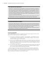
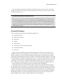
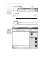
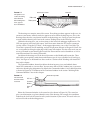
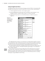
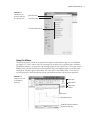
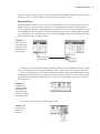
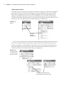
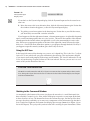
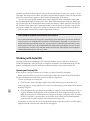
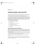
Part 1 RI PY RI GH TE D MA TE Chapter 1: Exploring the AutoCAD and AutoCAD LT Interface Chapter 2: Creating Your First Drawing Chapter 3: Setting Up and Using AutoCAD’s Drafting Tools Chapter 4: Organizing Objects with Blocks and Groups Chapter 5: Keeping Track of Layers and Blocks CO u u u u u AL The Basics Chapter 1 Exploring the AutoCAD and AutoCAD LT Interface Before you can start to use AutoCAD 2011’s new capabilities, you’ll need to become familiar with the basics. If you’re completely new to AutoCAD, you’ll want to read this first chapter carefully. It introduces you to many of AutoCAD’s basic operations, such as opening and closing files, getting a close-up look at part of a drawing, and changing a drawing. If you’re familiar with earlier versions of AutoCAD, you should review this chapter anyway to get acquainted with the features you haven’t already used. Autodesk releases new versions of AutoCAD every year. Part of this strategy is to introduce improvements that focus on a particular category of features. This latest version, AutoCAD 2011, includes several new features that are related to curves in both 2D drafting and 3D Modeling. There are also a number of enhancements that allow you to easily select similar objects in a drawing. The ability to make objects appear transparent has also been improved. Autodesk has discovered that the number of 3D users is on the upswing, so with this version, you’ll see some new 3D features that will give you more freedom to create 3D shapes. These features include some new ways to create surface forms and the editing tools that enable you to easily manipulate 3D solids and surfaces. The Materials feature has also been improved to make it easier to create realistic 3D renderings. You’ll get a chance to explore these new features and many more as you work through this book. Before you begin the exercise later in this chapter, make sure that you have loaded the sample files from this book’s companion DVD. See the introduction for details. In this chapter, you’ll learn about the following topics: •u Use the AutoCAD window •u Get a closer look with the Zoom command •u Save a file as you work •u Make changes and open multiple files Taking a Guided Tour In this section, you’ll get a chance to familiarize yourself with the AutoCAD screen and how you communicate with AutoCAD. As you do the exercises in this chapter, you’ll also get a feel for how to work with this book. Don’t worry about understanding or remembering everything you see in this chapter. You’ll get plenty of opportunities to probe the finer details of the program as you work through the later chapters. To help you remember the material, you’ll find a brief set of questions at the end of each chapter. For now, just enjoy your first excursion into AutoCAD. 4 | Chapter 1 Exploring the AutoCAD and AutoCAD LT Interface Get Additional Help on the DVD On the DVD accompanying this book, you’ll find a set of video tutorials that you can complete to practice the concepts presented in this chapter. Four tutorials give you an overview of the main topics of this chapter. The video entitled “The AutoCAD Window” covers the highlights of the material in “Taking a Guided Tour.” The video entitled “Getting Started and a Closer Look” touches on some of the material in “Working with AutoCAD.” “Saving a File as you Work” covers the material from the section with the same name in this chapter. Finally, “Opening Multiple Files” covers the material in “Working with Multiple Files.” While they don’t follow the exercise in this chapter word for word, these videos show you how AutoCAD behaves in real time, thereby giving you a more direct experience of the program. AutoCAD References in This Book In this chapter, and throughout the rest of the book, when I say AutoCAD, I mean both AutoCAD and AutoCAD LT. Some topics apply only to AutoCAD. In those situations, you’ll see an icon indicating that the topic applies only to AutoCAD and not to AutoCAD LT. If you’re using AutoCAD LT 2011, these icons can help you focus on the topics that are more relevant to your work. AutoCAD 2011 is designed to run on Windows XP and Windows Vista. This book was written using AutoCAD 2011 running on Windows XP Professional. Launching AutoCAD If you already installed AutoCAD (see Appendix B) and are ready to jump in and take a look, proceed with the following steps to launch the program: 1. Choose Start All Programs Autodesk AutoCAD 2011 AutoCAD 2011. You can also double-click the AutoCAD 2011 icon on your Windows Desktop. LT users will use AutoCAD LT 2011 in place of AutoCAD 2011. 2. Next, you see the Welcome screen, which offers a set of tutorials and videos showing you the new features of AutoCAD 2011. Close the Welcome screen by clicking the X at the far right side of the title bar. You can always get back to these tutorials through the Welcome screen option in the Help menu. 3. The AutoCAD window displays a blank default document named Drawing1.dwg. AutoCAD users may see the Sheet Set Manager palette to the left of the AutoCAD window. LT users may see the Info palette to the left of the AutoCAD window. If you’re using the trial version, you’ll see the Product License Activation window before step 2 in the preceding steps. This window shows you the number of days you have left in the trial version. It also enables you to activate the product if you purchase a license. Click the Try button to continue to the Welcome screen described in step 2. | Taking a Guided Tour 5 Now let’s look at the AutoCAD window in detail. Don’t worry if it seems like a lot of information. You don’t have to memorize it, but by looking at all the parts, you’ll be aware of what is available in a general way. Customization Based on Your Industry Before we move on, you may want to know about the Initial Setup dialog box. This dialog box lets you select the industry that is closest to the work you do. AutoCAD will then set up a workspace with the tools that will fit the needs of your industry. When you’re more comfortable with AutoCAD, you can go ahead and run the initial setup for your type of work. You can always open the Initial Setup dialog box from the User Preferences tab of the Options dialog box. See Appendix B for more on the Options dialog box. The AutoCAD Window The AutoCAD program window is divided into eight parts: •u Application menu •u Quick Access toolbar •u InfoCenter •u Ribbon •u Drawing area •u UCS icon (User Coordinate System icon) •u Command window •u Status bar Figure 1.1 shows a typical layout of the AutoCAD program window. You can organize the AutoCAD window into any arrangement you want and save it as a workspace. You can save and recall a workspace at any time using the Workspace Switching tool in the Quick Access toolbar (you’ll learn more about this tool in the next chapter). The default workspace in Figure 1.1 is called the 2D Drafting & Annotation workspace, which is one of several workspaces built into AutoCAD. Figure 1.2 shows AutoCAD’s 3D Modeling workspace, which has a different set of screen elements. Figure 1.2 also shows a standard AutoCAD drawing file with a few setting changes to give it a 3D appearance. Beneath these external changes, the underlying program is the same. You’ll learn more about workspaces later in this chapter and in Chapter 28. In the upper-left corner of the AutoCAD program window, the red AutoCAD icon features the Application menu, which offers a set of options not directly related to drawing; I’ll elaborate on this menu in the next section. The Quick Access toolbar at the top of the drawing area (shown in Figure 1.3) includes the basic file-handling functions that you find in nearly all Windows programs. The InfoCenter is AutoCAD’s online help facility; you’ll learn more about it in Chapter 2. The Ribbon provides nearly all the commands you’ll need using icon tools; you’ll learn more about the Ribbon in the section “Using the Ribbon” later in this chapter. 6 | Chapter 1 Exploring the AutoCAD and AutoCAD LT Interface Figure 1.1 A typical arrangement of the elements in the AutoCAD window. The Sheet Set Manager palette (or Info palette for LT) is closed for clarity. Quick Access Toolbar Application Menu Ribbon Drawing Area ViewCube Navigation Bar UCS Command Window Status Bar Figure 1.2 The 3D Modeling workspace offers an alternative arrangement of the elements in the AutoCAD window. InfoCenter | Taking a Guided Tour 7 Quick Access toolbar Figure 1.3 The Quick Access toolbar, featuring basic Windows file-handling functions, appears above the Ribbon. InfoCenter Ribbon tabs Ribbon panels Ribbon panel title bars The drawing area occupies most of the screen. Everything you draw appears in this area. As you move your mouse around, crosshairs appear to move within the drawing area. This is the drawing cursor that lets you point to locations in the drawing area. You’ll get your first chance to work with the drawing area later in the section “Picking Points in the Drawing Area.” Within the drawing area, you see three items in the lower-left and upper-right corners. The UCS icon appears in the lower-left corner. You’ll learn more about the UCS icon in a moment (see the section “Using the UCS Icon”). In the upper-right corner, you see the ViewCube. The ViewCube is primarily for 3D modeling, and you’ll learn more about it in Chapter 21. You’ll also see a navigation bar along the right edge of the AutoCAD window. This bar offers tools you can use to get around in your drawing. Basic tools like Zoom and Pan can be found here as well as some advanced tools for viewing 3D models. Just below the drawing area in the lower-left corner are the Model and Layout tabs. These tabs enable you to quickly switch between different types of views called the model and layout views. You’ll get to see firsthand how these work in a section called “Working with AutoCAD” later in this chapter. The Command window, located just below the drawing area, gives you feedback about AutoCAD’s commands as you use them. You can move and resize this window just as you move and resize other display components. By default, the Command window is in its docked position, as shown in Figure 1.4. I’ll elaborate on the Command window in the section “Working in the Command Window” later in this chapter. Model and Layout tabs Figure 1.4 The Command window and the status bar UCS icon Command Window Status Bar Coordinate readout Command line Below the Command window is the status bar (also shown in Figure 1.4). The status bar gives you information at a glance about the state of the drawing. For example, the coordinate readout at the far left of the status bar tells you the location of your cursor. The tools in the status bar offer aids to the drafting process. 8 | Chapter 1 Exploring the AutoCAD and AutoCAD LT Interface Using the Application Menu The Application menu offers tools to help you manage your AutoCAD files. It is basically the File pull-down menu from previous versions of AutoCAD. Try it out to see how it works firsthand: 1. Click the Application menu icon. A list of options appears. 2. Move the highlight cursor slowly down the list of options in the left column. As you highlight the options, additional options appear in a column to the right. 3. Highlight the Export option to see the different formats available for export (see Figure 1.5). Figure 1.5 The Export option in the Application menu showing the list of export options The Application menu also gives you a convenient way to find recently used files or to get to a file you already have open. If you move your cursor away from the list of options to the left in the Application menu, you’ll see Recent Documents in the upper-left portion of the menu. You’ll also see two icon tools named Open Documents and Recent Documents (see Figure 1.6). The Open Documents option lets you quickly change from one open file to another when you are viewing your files full-screen. The Recent Documents option displays a list of documents you’ve recently worked on. You can use the View tool in the upper-right portion of the Application menu to select the way the list of files is displayed in a manner similar to the way you would use the Windows Explorer View option. You can click this icon and select Small Images to have the list display the files with thumbnail images of their content. Hover over a filename and you will see a tool tip that displays a larger thumbnail of the drawing. | Taking a Guided Tour 9 Figure 1.6 The Open Documents and Recent Documents tools Open Documents Recent Documents List of Recent Documents Using the Ribbon The most prominent feature in the AutoCAD window, besides the drawing area, is the Ribbon (see Figure 1.7). This is where you’ll be selecting tools to draw, edit, or perform other functions. The Ribbon contains a set of panels representing groups of tools and features. The name of each Ribbon panel is found in its title bar at the bottom of the panel. Ribbon panels are further organized by the tabs that appear above them. All of the tools in the Ribbon offer tool tips and cue cards that provide a short description to help you understand what each tool icon represents. Figure 1.7 A typical cue card from a Ribbon panel tool Ribbon tabs Ribbon panels Ribbon panel title bars Tool name Description/tutorial Keyboard command equivalent Context-sensitive help 10 | Chapter 1 Exploring the AutoCAD and AutoCAD LT Interface Communicating with the Command Window and Dynamic Input Display AutoCAD is the perfect servant: It does everything you tell it to and no more. You communicate with AutoCAD by using tools and menu options. These devices invoke AutoCAD commands. A command is a single-word instruction you give to AutoCAD telling it to do something, such as draw a line (the Line tool in the Draw Ribbon panel) or erase an object (the Erase tool in the Modify Ribbon panel). Whenever you invoke a command, by either typing it or selecting a menu option or tool, AutoCAD responds by presenting messages to you in the Command window and the Dynamic Input display or by displaying a dialog box. The messages in the Command window, or in the Dynamic Input display, often tell you what to do next, or they may display a list of options. A single command often presents a series of messages, which you answer to complete the command. These messages serve as an aid to new users who need a little help. If you ever get lost while using a command or forget what you’re supposed to do, look at the Command window for clues. As you become more comfortable with AutoCAD, you’ll find that you won’t need to refer to these messages as frequently. As an additional aid, you can right-click to display a context-sensitive shortcut menu. That is, if you’re in the middle of a command, this menu displays a list of options specifically related to that command. For example, if you right-click your mouse before picking the first point for the Rectangle command, a menu opens, displaying the same options that are listed in the Command prompt plus some additional options. Finally, the Dynamic Input display allows you to enter dimensional data of objects as you draw them. Besides echoing the command-line messages, the Dynamic Input display shows temporary dimensions, coordinates, and angles of objects you’re drawing and editing. As you enter coordinate or angle values through the keyboard, they appear in the Dynamic Input display. You can easily turn the Dynamic Input display on or off by clicking the Dynamic Input tool in the status bar. When the Dynamic Input display is turned off, your keyboard input appears only in the Command window. If you see only the Ribbon tabs, click the arrowhead in the Ribbon Control tool. If you don’t even see the tabs, press the Esc key twice and type Ribbon↵. Move the arrow cursor onto one of the Ribbon panel tools and leave it there for a moment; you’ll see a tool tip appear just below the cursor. Hold the cursor there a bit longer and the tool tip changes to give you even more information about the tool. In most cases, you’ll be able to guess what each tool does by looking at its icon. The icon with an arc in the Draw Ribbon panel, for instance, indicates that the tool draws arcs; the one with the circle shows that the tool draws circles; and so on. For further clarification, the tool tip gives you the name of the tool. As a new user, you’ll find these tool tips helpful because they show you the name of the tool and a brief description of how to use it. Typically, when I ask you to select a tool, I’ll use the name shown in the tool tip to help you identify the tool. In the case of a tool with flyouts, the tool name changes under different conditions. For those tools, I’ll use a general description to identify the tool. You’ll learn more about flyouts a bit later in this chapter (see the section “Understanding Flyouts”). As you work through this book, I will ask you to select tools from the Ribbon panels. You’ll often be asked to switch between different tabs to select tools from other sets of panels. To make the process simpler to read, I’ll use a somewhat abbreviated description of a tools location. For | Taking a Guided Tour 11 example, for the Line tool, I’ll say, “Click the Line tool from the Home tab’s Draw panel.” For the Move tool, I’ll say, “Click the Move tool in the Home tab’s Modify panel.” Expanding Panels In addition to the visible tools, a few tools are hidden from view. You can expand many of the Ribbon panels to select more tools. If you see an arrowhead to the right of a panel’s title bar, you can click the title bar to expand the panel (see Figure 1.8). The set of tools expands to reveal some additional tools. If you move the cursor to the drawing area, the expanded panel shrinks to its original size. As an alternative, you can click the pushpin icon in the expanded panel title bar to lock the panel in its open position. Figure 1.8 The arrowhead in the panel title bar tells you that additional tools are available. Click the title bar to expand the panel. Pushpin icon From now on, I’ll refer to the location of additional tools as the “expanded panel.” For example, I’ll say, “Click the Ray tool in the expanded Draw panel” when I want you to select the Ray tool. If you are working on a smaller screen with low resolution, some of the Ribbon panels to the far right may look different from what you are shown in this book. On a low-resolution screen, AutoCAD will automatically reduce the size of the panels to the right so they show only their title (Figure 1.9). Figure 1.9 The Properties, Utilities, and Clipboard panels are reduced to single icons with a smaller AutoCAD window. To see the tools, hover over the panel (Figure 1.10). Figure 1.10 Hover over the panel to see the tools. 12 | Chapter 1 Exploring the AutoCAD and AutoCAD LT Interface Understanding Flyouts One more feature you’ll want to know about are the flyouts. Flyouts are similar to the expanded panels because you can click an arrowhead to gain access to additional tools. Unlike a whole panel, however, flyouts give you access to different methods for using a particular tool. For example, AutoCAD lets you draw circles in several different ways, so it offers a flyout for the Circle tool in the Home tab’s Draw panel. If you click the arrowhead next to the circle icon in the Draw panel, you’ll see additional tools for drawing circles (see Figure 1.11). Figure 1.11 Flyouts Click the flyout arrowhead to display additional tools. If you select a tool option from a flyout, that option becomes the default tool for the icon you chose. For example, if you hover your cursor over the circle icon in the Draw panel, you’ll see that the tool tip shows “Center, Radius” for the tool’s name. If you click the arrowhead next to the Center, Radius tool and select 2-Point, then 2-Point becomes the default tool and you’ll see “2-Point” for the name of the tool in the tool tip (see Figure 1.12). Figure 1.12 The tool with a flyout will change to the last tool used. Select 2-Point from the flyout and the default Circle tool becomes 2-Point. | Taking a Guided Tour 13 General Tool Names vs. Tool Tip Names Since the tool tip names of tools with flyouts can change, describing them by name can be a bit problematic. The name may have changed based on the last tool you used from a flyout. For this reason, if a tool has a flyout, I’ll refer to it by a general name that is related to the set of tools in a flyout rather than by the tool tip name. For example, I’ll call the circle icon tool the Circle tool rather than the Center, Radius tool. Likewise, I’ll refer to the magnifying glass icon in the View tab’s Navigate panel as the Zoom tool instead of the Extents tool. Zoom tool Tools vs. the Keyboard Throughout this book, you’ll be told to select tools from the Ribbon panels to invoke commands. For new and experienced users alike, the Ribbon panels offer an easy-to-remember method for accessing commands. If you’re an experienced AutoCAD user, you can type commands directly from the keyboard. Most of the keyboard commands you know and love still work as they did before. Many tools and commands have aliases. Aliases are one-, two-, or three-letter abbreviations of a command name. As you become more proficient with AutoCAD, you may find these aliases helpful. As you work through this book, the shortcuts will be identified for your reference. Finally, if you’re feeling adventurous, you can create your own aliases and keyboard shortcuts for executing commands by adding them to the AutoCAD support files. Chapter 28 discusses how to customize menus, Ribbon panels, toolbars, and keyboard shortcuts. Picking Points in the Drawing Area Now that you’ve seen the general layout of AutoCAD, take a look at the coordinate readout and the drawing cursor to get a sense of how the parts of the AutoCAD screen work together: 1. Move the cursor around in the drawing area. As you move it, notice how the coordinate readout changes to tell you the cursor’s location. It shows the coordinates in an X, Y, Z format. 2. Place the cursor in the middle of the drawing area and click the left mouse button. Move the cursor and a rectangle follows. This is a window selection; you’ll learn more about this window in Chapter 2. You also see a coordinate readout following the cursor and the message Specify opposite corner:. This display at the cursor is called the dynamic input display. You’ll learn more about it a little later in this chapter (Figure 1.13). 14 | Chapter 1 Exploring the AutoCAD and AutoCAD LT Interface Figure 1.13 The Dynamic Input Display cursor If you don’t see the Dynamic Input display, click the Dynamic Input tool in the status bar to turn it on. 3. Move the cursor a bit in any direction; then, click the left mouse button again. Notice that the window selection disappears, as does the Dynamic Input display. 4. Try picking several more points in the drawing area. Notice that as you click the mouse, you alternately start and end a window selection. If you happen to click the right mouse button, a shortcut menu appears. A right-click frequently opens a menu containing options that are context sensitive. This means the contents of the shortcut menu depend on the location where you right-click as well as the command that is active at the time. If there are no appropriate options at the time of the right-click, AutoCAD treats the rightclick as an ↵. You’ll learn more about these options as you progress through the book. For now, if you happen to open this menu by accident, press the Esc key to close it. Using the UCS Icon In the lower-left corner of the drawing area, you see an L-shaped line. This is the User Coordinate System (UCS) icon, which tells you your orientation in the drawing. This icon becomes helpful as you start to work with complex 2D drawings and 3D models. The X and Y indicate the X- and Y-axes of your drawing. Chapter 22 discusses this icon in detail. For now, you can use it as a reference to tell you the direction of the axes. If You Can’t Find the UCS Icon The UCS icon can be turned on and off, so if you’re on someone else’s system and you don’t see the icon, don’t panic. If you don’t see the icon or it doesn’t look as it does in this chapter, see Chapter 22 for more information. Working in the Command Window As mentioned, at the bottom of the screen, just above the status bar, is a small horizontal window called the Command window. Here, AutoCAD displays responses to your input. By default, it shows four lines of text. The bottom line shows the current messages, and the top lines show messages that have scrolled by or, in some cases, components of the current message that don’t fit in a single line. Right now, the bottom line displays the message Command (see Figure 1.4, earlier in this chapter). This prompt tells you that AutoCAD is waiting for your instructions. When | Working with AutoCAD 15 you click a point in the drawing area, you see the message Specify opposite corner:. At the same time, the cursor starts to draw a window selection that disappears when you click another point. The same message appears in the Dynamic Input display at the cursor. As a new user, pay special attention to messages displayed in the Command window and the Dynamic Input display because this is how AutoCAD communicates with you. Besides giving you messages, the Command window records your activity within AutoCAD. You can use the scroll bar to the right of the Command window to review previous messages. You can also enlarge the window for a better view. (Chapter 2 discusses these components in more detail.) Now, let’s look at AutoCAD’s window components in detail. The Command Window and Dynamic Input Display The Command window and the Dynamic Input display allow AutoCAD to provide text feedback on your actions. You can think of these features as a chat window to AutoCAD—as you enter commands, AutoCAD responds with messages. As you become more familiar with AutoCAD, you may find you don’t need to rely on the Command window and Dynamic Input display as much. For new and casual users, however, the Command window and Dynamic Input display can be helpful in understanding what steps to take as you work. Working with AutoCAD Now that you’ve been introduced to the AutoCAD window, you’re ready to try using a few AutoCAD commands. First you’ll open a sample file and make a few modifications to it. In the process, you’ll become familiar with some common methods of operation in AutoCAD. Opening an Existing File In this exercise, you’ll get a chance to see and use a typical Select File dialog box. Before you start, make sure you have installed the sample files for this book from the DVD. See the introduction for instructions on how to find the sample files. To start, you’ll open an existing file: 1. Click the close icon in the upper-right corner of the drawing area. It looks like an X. A message appears, asking whether you want to save the changes you’ve made to the current drawing. Click No. 2. Click the Open tool in the Quick Access toolbar to open the Select File dialog box. This is a typical Windows file dialog box, with an added twist: In the large Preview box on the right, you can preview a drawing before you open it, thereby saving time while searching for files. To the left is a panel known as the Places list in which you can find frequently used locations on your computer or the Internet (see Figure 1.14). If you don’t see a Preview box in the Select File dialog box, click the word Views in the upperright corner and select Preview from the list that appears. 16 | Chapter 1 Exploring the AutoCAD and AutoCAD LT Interface Figure 1.14 The Select File dialog box 3. In the Select File dialog box, open the Look In drop-down list and locate the Chapter 01 folder of the Mastering AutoCAD 2011 sample files. (You may need to explore the list to find it.) 4. Move the arrow cursor to the clip.dwg file and click it. Notice that the clip.dwg filename now appears in the File Name input box below the file list. The Preview box also now shows a thumbnail image of the file. Be aware that a thumbnail may not show for files from older versions of AutoCAD. 5. Click the Open button at the bottom of the Select File dialog box. AutoCAD opens the clip.dwg file, as shown in Figure 1.15. The clip.dwg file opens to display a layout view of the drawing. A layout is a type of view in which you lay out different views of your drawing in preparation for printing. You can tell you are in a layout view by the white area over the gray background. This white area represents your drawing on a printed page. This view is like a print preview. Figure 1.15 The Layout1 view of the clip.dwg file | Working with AutoCAD 17 Also note that the AutoCAD window’s title bar displays the name of the drawing. This offers easy identification of the file. This particular file contains both 2D drawings and a 3D model of a typical locking clip. The layout view shows a top, front, and right-side view as well as an isometric view. Getting a Closer Look One of the most frequently used commands is Zoom, which gives you a closer look at part of your drawing. This command offers a variety of ways to control your view. In this section, you’ll enlarge a portion of the clip drawing to get a more detailed look. To tell AutoCAD which area you want to enlarge, you use what is called a zoom window. You’ll start by switching to a Model Space view of the drawing. The Model Space view places you in a workspace where you do most of your drawing creation and editing. Follow these steps: 1. Click the Model tab below the drawing area, or if you don’t see the tab, click the Model tool in the status bar (Figure 1.16). Your view changes to show the full 3D model with the 2D representations of the model (see Figure 1.17). 2. Type PLAN↵W↵. Your display changes to a two-dimensional view looking down on the drawing, as shown in Figure 1.18. Figure 1.16 Click the Model tab (left) or the Model tool in the status bar (right). Figure 1.17 3D model with 2D representations of the model 18 | Chapter 1 Exploring the AutoCAD and AutoCAD LT Interface Figure 1.18 Placing the zoom window around the clip First click here… And then click here. 3. Click the Zoom Window tool from the Zoom flyout in the navigation bar (Figure 1.19). Remember that to open the flyout, you need to click the arrowhead next to or below the tool. Figure 1.19 The Zoom Window tool from the Zoom flyout in the navigation bar. Flyout arrowhead You can also click the Window tool from the Zoom flyout in the View tab’s Navigate panel (Figure 1.20) or type the command Z↵. Figure 1.20 The Zoom flyout and Window tool in the View tab’s Navigate panel. Click the flyout arrowhead. Select Window. 4. The Dynamic Input display shows the Specify corner of window: prompt with some options. Look at the image in Figure 1.18. Move the crosshair cursor to a location similar to the one shown in the figure; then, left-click the mouse. Move the cursor and the rectangle appears with one corner fixed on the point you just picked; the other corner follows the cursor. | Working with AutoCAD 19 5. The Dynamic Input display now shows the Specify first corner: and Specify opposite corner: prompts. Position the other corner of the zoom window so it encloses the lower image of the clip, as shown in Figure 1.18, and left-click the mouse again. The clip enlarges to fill the screen. In this exercise, you used the Window option of the Zoom command to define an area to enlarge for your close-up view. You saw how AutoCAD prompts you to indicate first one corner of the window selection and then the other. These messages are helpful for first-time users of AutoCAD. You’ll use the Window option frequently—not just to define views but also to select objects for editing. Getting a close-up view of your drawing is crucial to working accurately, but you’ll often want to return to a previous view to get the overall picture. To do so, choose Previous from the Zoom flyout in the View tab’s Navigate panel (Figure 1.21). Figure 1.21 The Zoom Previous option Do this now and the previous view—the one showing the entire clip—returns to the screen. You can also find the Zoom Previous option in the navigation bar’s Zoom flyout. You can quickly enlarge or reduce your view by using the Zoom Realtime option of the Zoom command. Follow these steps to change your view with Zoom Realtime: 1. Click the Zoom Realtime tool from the navigation bar’s Zoom flyout. You can also right-click in the drawing area and select Zoom from the shortcut menu or select Zoom Realtime from Zoom flyout on the View tab’s Navigate panel. 2. Place the Zoom Realtime cursor slightly above the center of the drawing area, and then click and drag downward. Your view zooms out to show more of the drawing. 3. While still holding the left mouse button, move the cursor upward. Your view zooms in and enlarges. When you have a view similar to the one shown in Figure 1.22, release the mouse button. (Don’t worry if you don’t get exactly the same view as the figure. This is just for practice.) 4. You’re still in Zoom Realtime mode. Click and drag the mouse again to see how you can further adjust your view. To exit, you can select another command besides a Zoom or Pan, press the Esc key, or right-click your mouse and choose Exit from the shortcut menu. 5. Right-click now and choose Exit from the shortcut menu to exit the Zoom Realtime command. 20 | Chapter 1 Exploring the AutoCAD and AutoCAD LT Interface Figure 1.22 The final view you want to achieve in step 3 of the exercise If you prefer, you can use the wheel on your mouse to zoom and pan over your view. Roll the wheel to zoom in and out or click and drag the wheel to pan. Be aware that Zoom Realtime offers finer control over the amount of magnification compared to the mouse wheel. As you can see from this exercise, you have a wide range of options for viewing your drawings, just by using a few tools. These tools are all you need to control the display of 2D drawings. Saving a File as You Work It’s a good idea to save your file periodically as you work on it. As with any Windows program, you can save it under its original name (click the Save tool on the Quick Access toolbar) or under a different name (choose Save As from the Application menu), thereby creating a new file. By default, AutoCAD automatically saves your work at 10-minute intervals under a name that is a combination of the current filename plus a number and that ends with the .sv$ filename extension; this is known as the Automatic Save feature. Using settings in the Options dialog box or system variables, you can change the name of the autosaved file and control the time between autosaves. See “The Open and Save Tab” in Appendix B for details. Making Changes You’ll frequently make changes to your drawings. One of AutoCAD’s primary advantages is the ease with which you can make changes. The following exercise shows you a typical sequence of operations involved in changing a drawing: 1. Use the Save As option in the Application menu to save the current clip.dwg file under the name MyFirst. For convenience, you can save your files in the My Documents folder. 2. From the Home tab’s Modify panel, click the Erase tool (the one with a pencil eraser touching paper). This activates the Erase command. | Working with AutoCAD 21 Notice that the cursor has turned into a small square. This square is called the pickbox. You also see Select objects: in the Command window and the Dynamic Input display. This message helps remind new users what to do. 3. Move the pickbox over the drawing, placing it on various parts of the clip. Don’t click anything yet. Notice that as you hover your cursor over objects with the pickbox, they’re highlighted. This helps you see the objects that the pickbox is likely to select should you click the left mouse button. 4. Place the pickbox on the crosshatch pattern of the clip (see Figure 1.23), and click. The crosshatch changes in appearance from a dark highlight to a light highlight. The pickbox and the Select objects: prompt remain, indicating that you can continue to select objects. 5. Press ↵. The crosshatch disappears. You’ve just erased a part of the drawing. Figure 1.23 Erasing a portion of the clip Click here. “I Can’t Find My Automatic Saves!” As an IT manager at ELS Architecture and Urban Planning, one of the most common questions I get is “Where does AutoCAD put the Automatic Save files?” By default, in Windows XP, the Automatic Save file is stored in C:\Documents and Settings\User Name\Local Settings\Temp\. You can find the exact location for your system by typing Savefilepath↵ at the Command prompt. This file location is often set as a hidden folder, so you may need to set up Windows Explorer to display hidden folders before you can get to the Automatic Save file. You can also specify a different location for the Automatic Save files. See Appendix B for information on how to locate hidden files and specify a location for your files. 22 | Chapter 1 Exploring the AutoCAD and AutoCAD LT Interface In this exercise, first you issued the Erase command, and then you selected an object by using a pickbox to click it. The pickbox tells you that you must select items on the screen, and it shows you what you’re about to select by highlighting objects as you hover the cursor over them. Once you’ve clicked an object or a set of objects, press ↵ to move on to the next step. This sequence of steps is common to many of the commands you’ll work with in AutoCAD. You can also click an object or a set of objects and then press the Delete key. Working with Multiple Files You can have multiple documents open at the same time in AutoCAD. This can be especially helpful if you want to exchange parts of drawings between files or if you want another file open for reference. Try the following exercise to see how multiple documents work in AutoCAD: 1. Click the New tool on the Quick Access toolbar to open the Select Template dialog box. If you see the Create New Drawing dialog box, click the Start From Scratch button and select Imperial; then click OK and AutoCAD will display a default document. You’ll learn more about the Create New Drawing dialog box in Chapter 2. 2. Make sure acad.dwt is selected, and then click Open. 3. In the View tab’s Windows panel, click Tile Vertically to get a view of both drawing files. When you create a new file in AutoCAD, you’re actually opening a copy of a template file, as you saw in step 1. A template file is a blank file that is set up for specific drawing types. The acad.dwt file is a generic template set up for Imperial measurements. Another template file, called acadiso.dwt, is a generic template useful for metric measurements. Other templates are set up for specific drawing-sheet sizes and measurement systems. You’ll learn more about templates in Chapter 6. Next, let’s try drawing a rectangle to see how AutoCAD behaves while drawing objects: 1. Click the Rectangle tool in the Home tab’s Draw panel, as shown in Figure 1.24. Figure 1.24 Click the Rectangle tool in the Draw panel. Notice that the Command window now shows the following prompt: Specify first corner point or [Chamfer/Elevation/Fillet/Thickness/Width]: AutoCAD is asking you to select the first corner for the rectangle and, in brackets, it’s offering a few options that you can take advantage of at this point in the command. Don’t worry about those options right now. You’ll have an opportunity to learn about command options in Chapter 2. You also see the same prompt, minus the bracketed options, in the Dynamic Input display at the cursor. You can view the command options at the cursor by pressing the down arrow key on your keyboard. | Working with AutoCAD 23 2. Click a point roughly in the lower-left corner of the drawing area, as shown in Figure 1.25. Now, as you move your mouse, a rectangle follows the cursor, with one corner fixed at the position you just selected. You also see the following prompt in the Command window, with a similar prompt in the Dynamic Input display: Specify other corner point or [Area/Dimensions/Rotation]: Figure 1.25 Click here to start the rectangle. Selecting the first point of a rectangle 3. Click another point anywhere in the upper-right region of the drawing area. A rectangle appears (see Figure 1.26). You’ll learn more about the different cursor shapes and what they mean in Chapter 2. 4. Let’s try copying objects between these two files. Click in the window with the clip drawing to make it active. Figure 1.26 After you’ve selected the first point of the rectangle, you’ll see a rectangle follow the motion of your mouse. 24 | Chapter 1 Exploring the AutoCAD and AutoCAD LT Interface 5. Click All from the Zoom flyout in the View tab’s Navigate panel to get an overall view of the drawing (see Figure 1.27). You can also click the Zoom All tool from the navigation bar’s Zoom flyout. Figure 1.27 The Zoom All option gives you an overall view of your drawing. 6. Click the 2D version of the clip at the bottom of the drawing to select it. A series of squares and arrows appears on the drawing. These are called grips, and you’ll learn more about them in the next chapter (see Figure 1.28). Figure 1.28 Grips shown in the 2D drawing Select this part of the drawing. 7. Right-click and select Clipboard and then Copy. 8. Click inside the other drawing window to make it active. 9. Right-click and select Clipboard and then Paste. The clip appears at the cursor in the new drawing. | The Bottom Line 25 10. Position the clip in the middle of the rectangle you drew earlier and left-click the mouse. The clip is copied into the second drawing. 11. This ends the exercises for this chapter. Save the new file as My Clip and then exit AutoCAD. You don’t have to save the clip.dwg file. Note that you’ve had two files open at once. You can have as many files open as you want as long as your computer has adequate memory to accommodate them. You can control the individual document windows as you would any window, using the window control buttons in the upper-right corner of the document window. Adding a Predrawn Symbol with the Tool Palettes In the preceding exercise, you saw how you can easily copy an object from one file to another by using the standard Windows Cut and Paste feature. AutoCAD offers several tool palettes that enable you to click and drag predrawn objects into your drawing. You can open the tool palettes by clicking the Tool Palettes tool in the View tab’s Palettes panel, as shown in Figure 1.29. Figure 1.29 The Tool Palettes tool opens a set of tool palettes. View tab Tool Palettes tool in the Palettes panel Once the tool palettes are open, you can select a tab in the tool palettes containing the predrawn objects you want to use and then click the specific object you want to add. The object appears at the cursor, ready for you to select a location (see Figure 1.30). In addition to predrawn objects, the tool palettes offer a way to add hatch patterns and other components quickly to your drawing. They’re great tools to help you manage your library of custom, predrawn symbols. Chapter 29 shows you how to use and customize the tool palettes. The Bottom Line Use the AutoCAD window. AutoCAD is a typical Windows graphics program that makes use of menus, toolbars, Ribbon panels, and palettes. If you’ve used other graphics programs, you’ll see at least a few familiar tools. Master It Name the components of the AutoCAD window you can use to select a function. 26 | Chapter 1 Exploring the AutoCAD and AutoCAD LT Interface Figure 1.30 The tool palettes offer predrawn symbols that you can easily place in your drawings. Select a tab containing predrawn symbols you want to use. Click on a symbol. The symbol appears at the cursor ready to be placed in the drawing. Get a closer look with the Zoom command. One of the first things you’ll want to learn is how to manipulate your views. The Zoom command is a common tool in graphics programs. Master It Name at least two ways of zooming into a view. Save a file as you work. Nothing is more frustrating than having a power failure cause you to lose hours of work. It’s a good idea to save your work frequently. AutoCAD offers an Automatic Save feature that can be a lifesaver if you happen to forget to save your files. Master It How often does the AutoCAD Automatic Save feature save your drawing? Make changes and open multiple files. As with other Windows programs, you can have multiple files open and exchange data between them. Master It With two drawings open, how can you copy parts of one drawing into the other?