1
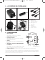
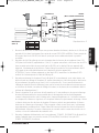
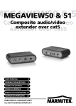
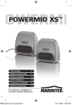
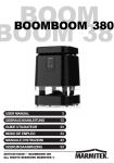
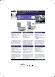
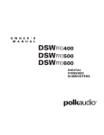
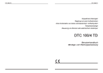
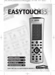
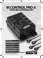
20177_20080901_UG_IR_CONTROL_PRO8_def
18-09-2008
10:55
Pagina 1
ONTROL P
IR CONTROL PRO 8
™
INFRARED EXTENDER SET
USER MANUAL
3
GEBRAUCHSANLEITUNG
9
GUIDE UTILISATEUR
15
MODO DE EMPLEO
21
MANUALE D’ISTRUZIONE
27
GEBRUIKSAANWIJZING
33
20177 / 20080901 • IR CONTROL PRO 8TM
© ALL RIGHTS RESERVED MARMITEK®2007
20177_20080901_UG_IR_CONTROL_PRO8_def
2
18-09-2008
10:55
Pagina 2
© MARMITEK
20177_20080901_UG_IR_CONTROL_PRO8_def
18-09-2008
10:55
Pagina 3
•
•
•
•
•
•
To prevent short circuits, this product should only be used inside and only in dry spaces.
Do not expose the components to rain or moisture. Do not use the product close to a
bath, swimming pool etc.
Do not expose the components of your systems to extremely high temperatures or bright
light sources.
In case of improper usage or if you have altered and repaired the product yourself, all guarantees
expire. Marmitek does not accept responsibility in the case of improper usage of the product or
when the product is used for purposes other than specified. Marmitek does not accept
responsibility for additional damage other than covered by the legal product responsibility.
Do not open the product: the device may contain live parts. The product should only be
repaired or serviced by a qualified repairman.
Only connect the adapter to the mains after checking whether the mains voltage is the
same as the values on the identification tags. Never connect an adapter when it is
damaged. In that case, contact your supplier.
This product is not a toy. Keep out of reach of children.
TABLE OF CONTENTS
INTRODUCTION
1. OPERATION
2. CONTENTS OF THE PACKAGE
3. INSTALLATION
4. FREQUENTLY ASKED QUESTIONS
5. TECHNICAL DATA
6. OPTIONAL ACCESSORIES
3
3
4
4
6
7
8
INTRODUCTION
Congratulated on buying the Marmitek Ir Control Pro 8. With it you can extend the IR (infrared) signals of
remote controls. The IR Control Pro 8 makes it possible to control up to 8 A/V devices while these are in a
closed cupboard or when your A/V equipment is out of sight. The IR Control Pro 8 is a universal IR
extender set and is exchangeable with several other IR products of Marmitek and many other makes.
1. OPERATION
The IR receiver of the IR Control Pro 8 receives the signal of your remote control and converts it into an
electric signal which is relayed to the IR module. Up to 8 IR LEDs can be connected to this module. These
IR LEDs make an IR signal of the electrical signal which is received by the IR sensor of your a/V apparatus.
All signals of your remote control are relayed one to one to all connected IR LEDs. If the IR receiver
receives a signal of your remote control it will light up so that you can check the system if it works
properly.
IR CONTROL PRO 8TM
3
ENGLISH
SAFETY WARNINGS
20177_20080901_UG_IR_CONTROL_PRO8_def
18-09-2008
10:55
Pagina 4
2. CONTENTS OF THE PACKAGE
A
B
D
E
C
A. 1 x IR Module
B. 1 x IR Receiver
(with connector)
C. 2 x IR Extension cable
with 2 IR LEDs
D. 1 x Power adaptor
E. 1 x Manual
3. INSTALLATION
1
1
2
2
4
3
V+
G
ST
IR
3
4
5
1.
2.
3.
4.
STATUS
POWER
(INPUT)
(EMITTERS 1 till 4)
5. Fastening holes
4
Picture 1
Connection for a STATUS power adapter (not supplied)
Connection for the POWER power adapter (supplied)
Connection for max. 3 IR receiver(s) (1 x supplied)
Connection for max. 4 IR Extension cables with each 2 IR LEDs.
(2 x supplied)
for stable assembling of the IR Module on a smooth underground.
© MARMITEK
18-09-2008
10:55
Pagina 5
IR LEDs
(Max. 4 IR extender cables)
IR Module
1
2
V+
G
ST
IR
IR Receiver
(Max. 3)
09734
Black
G
Black
ST -
-
IR
White
White
4
09733
V+ Black
Black
3
Picture 2
To check the proper working of the system it is advisable first to test the formation as
planned. For this reason connect everything as described as follows but don’t fix or screw the
components yet.
1. Install the IR Module at a place within reach behind or next to your A/V equipment and
near a 230V plug (230Volt/50Hz). Take into account the length of the cable of the IR
LEDs and make sure that the connections are kept accessible if possible.
2. Plug the required IR Extension cables (with the 2 IR LEDs) into the IR Module (Picture 1 nr. 4).
A self-adhesive foil is supplied with the IR LEDs. With that you can fasten the IR LEDs to
the IR window of your A/V equipment. Note: it’s tricky work. First test the position and
working of the IR LEDs before fixing them permanently to the IR window of your A/V
equipment. Note: If you use only one of the 2 LEDs, then leave the second IR LED
unused. Never remove it from the IR extension cable!
3. Now connect the IR Receiver to the IR Module, for your convenience the connection clip
has been connected to the wiring of the IR Receiver, take care when plugging in of the
correct position (nuts up) and colours of the wiring. When you have to disconnect the
wiring for instance because a connecting clip won’t go through a hole in the furniture,
connect afterwards the wiring to the clip according to the connection scheme in Picture 2.
4. Place the supplied IR receiver in such a way that it is visible for your infrared remote
control and if possible not in the vicinity of potential sources of disturbance like direct sun
light, TL lighting, energy saving lamps etc. The infrared LED indicator on the IR receiver
lights up or flashes when it receives an infrared signal. Use the LED indicator to place the
IR receiver in the place with the least interference (LED indicator is not activated or only
faintly lights up). Because of the supplied self-adhesive strip installation is possible almost
everywhere. Experiment for the correct place before you fix the IR receiver definitively.
Note: The adhesive strip can cause discoloration on certain surfaces or leave glue
remnants by removal.
5. Connect the power adapter to the ‘POWER’ connection of the IR module and plug the
adapter to a wall plug. (230V/50Hz). Check if the ‘POWER’ LED is on.
IR CONTROL PRO 8TM
5
ENGLISH
20177_20080901_UG_IR_CONTROL_PRO8_def
20177_20080901_UG_IR_CONTROL_PRO8_def
18-09-2008
10:55
Pagina 6
TIP:
• With the help of the supplied IR Extension cables 4 A/V devices can be controlled with
the IR Module, which is simply to be extended to maximal 8 A/V devices with the help of
one ore two optional obtainable IR LEDs. (Art. Nr. 09843).
• With the help of an extra IR Receiver you can also control your A/V equipment from
another place (if desired you can extend the connection cable of the IR receiver.)
- built-in IR receiver Art. nr. 09733
- built-on IR receiver Art. nr. 09734
STATUS CONNECTION (Power adapter not supplied)
Power adapter 12V/200mA (optional)
1
Circuit power on back
of A/V equipment
230V/50Hz
2
V+
G
ST
IR
3
4
Picture 3
You can send a Power Status signal to the IR module by connecting a Power adapter to this
connection (not supplied; 12VDC/200mA), which is switched by the device to be controlled.
When the A/V device or contact is switched in a LED will light up in the IR Module so that
you can see that the A/V device is switched in. (see picture 3).
4. FREQUENTLY ASKED QUESTIONS
The IR Receiver does not respond to signals of my remote control.
Observe the following directions:
• Check the connections, is the power adapter connected to the correct connection? This
must be connected to the ‘POWER’ connection, the green lamp will burn when the
power adapter is plugged in the plug.
• Both the built-in and the built-on IR Receiver has a reception sensibility of about 10
metres at an opening Angle of 90 degrees. Range is also dependent on the remote
control used. The IR reception indication LED in the IR Receiver will light up at reception
of an IR signal.
6
© MARMITEK
20177_20080901_UG_IR_CONTROL_PRO8_def
•
10:55
Pagina 7
The IR Receiver does not work together with some A/V apparatus and models which use
a higher IR frequency like for instance Bang&Olufsen (B&O) .
Sometimes it may be that the IR Receiver is troubled by so-called interference (direct
sunlight, TL lighting, energy saving lamps etc). In that case you ought to re-direct the IR
Receiver a bit for a better result.
ENGLISH
•
18-09-2008
Can I use the IR Receiver near a flat screen TV ?
Yes, sometimes it may happen that the IR receiver suffers some disturbance from the TV
screen. Then move the IR receiver in such a way that it is not in the direct radiation of the TV.
It is easy to test. The infrared LED indicator on the IR receiver lights up or flashes when it
receives an infrared signal. Use the LED indicator to place the IR receiver in the place with the
least interference (LED indicator is not activated or only faintly lights up).
Do you have questions that were not answered in the above mentioned ?
Then look at www.marmitek.com.
5. TECHNICAL DATA
IR Module
Feed POWER:
Feed STATUS:
IR LEDs connections:
IR Receiver connection:
Dimensions:
230VAC/50Hz, 12VC 500mA (supplied).
12VDC 200mA. Plug, - 5.5 mm outside / + 2.1 mm
inside (not supplied).
4 x 3.5 mm jack plug (mono).
1 Connector for maximal 3 parallel connected receivers.
85x49x24xmm (fastening points inclusive).
IR receiver built-on
Frequency range:
IR reception range:
Length of cable:
IR receiver:
IR reception angle:
Dimensions receiver bloc:
30-100 KHz.
V+: Black
IR: White
± 10 metres.
2 metres, extendable to max 300 metres (UTP or equivalent).
Reception indication LED.
90° (+45°/-45° from centre).
51x10x8mm.
G: Black
IR receiver built-in (optional)
G: Black
V+: Black
Frequency range:
30-100 KHz.
IR: White
IR reception range:
± 10 metres
Length of cable:
2 metres, extendable to max 300 metres (UTP or equivalent).
IR receiver:
Reception indication LED.
IR reception angle:
90°(+45°/-45° from centre)
Dimensions receiver:
Diameter 11.7 mm - Drilling size 12 mm - Length 50 mm
Built-in depth 55 mm - Maximal thickness of material 40 mm.
IR CONTROL PRO 8TM
7
20177_20080901_UG_IR_CONTROL_PRO8_def
IR Extension cable
Connection:
IR LEDs:
Length of cable:
18-09-2008
10:55
Pagina 8
3.5mm jack plug
2x IR LED
3 metres (from plug to division 2m, from division to LED 1m).
6. OPTIONAL ACCESSORIES
Extra IR receiver
Built-on Art.nr. : 09734
Panel Mount Art.nr.: 09733
With the help of an extra IR Receiver you can also
operate your A/V from another room. See for
more information www.marmitek.com.
09733
09734
Extra IR Extension cable Art.nr.: 09843
With the help of an extra IR extension cable you can operate 2 extra A/V
devices. (Extendable to maximal 8 A/V apparatus). See for more information
www.marmitek.com.
Marmitek EasyControl8™ Art.nr.: 09662
Marmitek EasyTouch35™ Art.nr.: 09664
With both universal remote controls you can control 8 A/V devices:
TV, video, DVD, cable, satellite, audio, Marmitek X10 and digital
satellite. Through pre-programmed codes and learner function they
work always. The EasyTouch35™ is provided with a convenient
Touchscreen with pale blue screen lighting. See for more information
www.marmitek.com.
09843
09662
09664
Environmental Information for Customers in the European Union
European Directive 2002/96/EC requires that the equipment bearing this symbol on the product and/or its packaging
must not be disposed of with unsorted municipal waste. The symbol indicates that this product should be disposed
of separately from regular household waste streams. It is your responsibility to dispose of this and other electric and
electronic equipment via designated collection facilities appointed by the government or local authorities. Correct
disposal and recycling will help prevent potential negative consequences to the environment and human health. For more
detailed information about the disposal of your old equipment, please contact your local authorities, waste disposal service, or
the shop where you purchased the product.
8
© MARMITEK
20177_20080901_UG_IR_CONTROL_PRO8_def
18-09-2008
10:55
Pagina 9
•
•
•
•
•
•
Um Kurzschluss vorzubeugen, dieses Produkt bitte ausschließlich innerhalb des Hauses und nur in
trockenen Räumen nutzen. Setzen Sie die Komponenten nicht Regen oder Feuchtigkeit aus. Nicht
neben oder nahe eines Bades, Schwimmbades usw. verwenden.
Setzen Sie die Komponente Ihres Systems nicht extrem hohen Temperaturen oder starken
Lichtquellen aus.
Bei einer zweckwidrigen Verwendung, selbst angebrachten Veränderungen oder selbst
ausgeführten Reparaturen verfallen alle Garantiebestimmungen. Marmitek übernimmt bei einer
falschen Verwendung des Produkts oder bei einer anderen Verwendung des Produktes als für den
vorgesehenen Zweck keinerlei Produkthaftung. Marmitek übernimmt für Folgeschäden keine
andere Haftung als die gesetzliche Produkthaftung.
Dieses Produkt ist kein Spielzeug. Außer Reichweite von Kindern halten.
Das Produkt niemals öffnen (ausgen.des Batteriefachs): Das Gerät kann Teile enthalten, worauf
lebensgefährliche Stromspannung steht. Überlassen Sie Reparaturen oder Wartung nur Fachleuten.
Schließen Sie den Netzadapter erst dann an das Stromnetz an, nachdem Sie überprüft haben, ob
die Netzspannung mit dem auf dem Typenschild angegeben Wert übereinstimmt. Schließen Sie
niemals einen Netzadapter an, wenn diese beschädigt sind. In diesem Fall nehmen Sie Kontakt mit
Ihrem Lieferanten auf.
INHALTSANGABE
EINFÜHRUNG
1. BETRIEB
2. VERPACKUNGSINHALT
3. INSTALLATION
4. HÄUFIG GESTELLTE FRAGEN
5. TECHNISCHE DATEN
6. OPTIONAL ERHÄLTLICH
9
9
10
10
12
13
14
EINFÜHRUNG
Herzlichen Glückwunsch zum Erwerb des Marmitek IR Control Pro 8™. Mit diesem Set können
Sie IR (Infrarot-) Signale von Fernbedienungen verlängern. Das IR Control Pro 8™ Set ermöglicht
es, bis zu 8 A/V Geräte zu bedienen, während diese sich in einem geschlossenen Schrank oder
außer Sichtweite befinden. Das IR Control Pro 8™ ist ein universelles IR Verlängerungsset und mit
verschiedenen anderen Marmitek® IR Produkten und vielen anderen Marken austauschbar.
1. BETRIEB
Der IR Empfänger des IR Control Pro 8™ Sets empfängt das Signal Ihrer Fernbedienung und setzt
dieses in ein elektrisches Signal um, das an das IR Modul weitergegeben wird. An dieses Modul
können bis zu 8 IR LED angeschlossen werden. Diese IR LED wandeln das elektrische Signal wieder in
ein IR Signal um, was von dem IR Sensor Ihres A/V Geräts empfangen wird. Alle Signale Ihrer
IR CONTROL PRO 8TM
9
DEUTSCH
SICHERHEITSHINWEISE
20177_20080901_UG_IR_CONTROL_PRO8_def
18-09-2008
10:55
Pagina 10
Fernbedienung werden eins zu eins an alle angeschlossenen IR LED weitergegeben. Wenn der IR
Empfänger ein IR Signal Ihrer Fernbedienung empfängt, so wird diese aufleuchten sodass Sie das
System auf korrekten Betrieb kontrollieren können.
2. VERPACKUNGSINHALT
A
B
D
E
C
A 1x IR Modul
B 1x IR Empfänger
(mit Connector)
C 2x IR Verlängerungskabel
mit 2 IR LED
D 1x Speisungsadapter
E 1x Gebrauchsanleitung
3. INSTALLATION
1.
2.
3.
4.
5.
10
STATUS
Anschluss für einen STATUS Speisungsadapter
(nicht mitgeliefert).
POWER
Anschluss für den POWER Speisungsadapter
(mitgeliefert).
(INPUT)
Anschluss für max. 3 IR Empfänger (1x
mitgeliefert).
(EMITTERS 1 t/m 4)
Anschluss für max. 4 IR Verlängerungskabel mit
je 2 IR LED, (2x mit enthalten).
Befestigungslöcher für eine stabile Montage
des IR Moduls auf einem flachen Untergrund.
IR Modul
1
1
2
2
4
3
V+
G
ST
IR
3
4
5
Abbildung 1
© MARMITEK
20177_20080901_UG_IR_CONTROL_PRO8_def
18-09-2008
10:55
Pagina 11
IR LED
(Max. 4 IR-Verlängerungskabels)
IR Modul
1
2
09734
IR Empfänger
(Max. 3)
Schwarz
G
Schwarz
ST -
-
IR
Weiß
Weiß
4
09733
V+ Schwarz
Schwarz
3
DEUTSCH
DEUTSCH
V+
G
ST
IR
Abbildung 2
Zur Kontrolle des korrekten Systembetriebs empfehlen wir, die von Ihnen geplante Aufstellung
zunächst zu testen. Schließen Sie dazu alles an, wie im Nachfolgenden umschrieben, kleben oder
schrauben Sie die Komponenten jedoch noch nicht fest.
1. Montieren Sie das IR Modul an einen erreichbaren Ort hinter oder neben Ihren A/V Geräten und
nahe einer 230V Steckdose (230Volt/50Hz). Berücksichtigen Sie die Kabellänger der IR LED und
achten Sie darauf, dass die Anschlüsse möglichst erreichbar bleiben.
2. Stecken Sie die benötigten IR Verlängerungskabel (mit den 2 IR LED) in das IR Modul (Abbildung
1 Nr. 4). Zu den IR LED ist eine selbstklebende Folie mitgeliefert. Hiermit können Sie die IR LED an
das IR Fenster Ihres A/V Geräts befestigen. Achtung: dies erfordert große Genauigkeit. Testen Sie
zunächst die Position und den Betrieb der IR LED, bevor Sie diese definitiv an das IR Fenster Ihres
A/V Geräts festkleben.
ACHTUNG: Wenn Sie Sie nur einen der 2 LED verwenden, lassen Sie dann den zweiten IR LED
ungebraucht. Entfernen Sie diesen niemals vom IR Verlängerungskabel!
3. Schließen Sie nun den IR Empfänger an das IR Modul an. Die Anschlussklemme ist, um Ihnen die
Arbeit zu erleichtern, bereits an die Drähte des IR Empfängers befestigt. Achten Sie beim Einstecken
auf die richtige Position (Schrauben oben) und auf die Farben der Drähte. Wenn Sie die Drähte lösen
müssen, weil z.B. die Anschlussklemme nicht durch die Öffnung des Möbelstücks passt, schließen
Sie dann die Drähte wieder gemäß dem Anschlussschema in Abbildung 2 an die Klemme an.
4. Bringen Sie den mitgelieferten IR Empfänger so an, dass dieser in Sichtkontakt zu Ihrer InfrarotFernbedienung steht und sich möglichst weit entfernt von eventuellen Störquellen wie direkt
einfallendes Sonnenlicht, TL Beleuchtung, Sparlampen, usw. befindet. Die Infrarot LED Anzeige
am IR Empfänger leuchtet auf oder blinkt, wenn diese Infrarotstrahlung empfängt. Verwenden Sie
diese LED Anzeige, um den IR Empfänger an einer störungsfreien Stelle anzubringen (LED wird
nicht oder kaum ansprechen). Durch den mitgelieferten, selbstklebenden Klebestreifen ist
Anbringung nahezu überall möglich. Experimentieren Sie zur Feststellung des richtigen Platzes,
bevor Sie den IR-Empfänger definitiv festkleben. Achtung! Der Klebestreifen kann auf bestimmten
Oberflächen zu Verfärbungen führen oder bei Entfernung Leimreste hinterlassen.
5. Schließen Sie den Speisungsadapter an den “POWER” Anschluss Ihres IR Moduls an und stecken Sie
den Adapter in eine Steckdose (230V/50Hz). Überprüfen Sie, ob die “POWER” LED eingeschaltet ist.
IR CONTROL PRO 8TM
11
20177_20080901_UG_IR_CONTROL_PRO8_def
18-09-2008
10:55
Pagina 12
TIPP:
• Mit dem IR Modul können mithilfe des mitgelieferten IR Verlängerungskabels 4 A/V
Geräte bedient werden. Diese können mit 1 oder 2 optional erhältlichem IR LEDs
kinderlicht auf bis zu max. 8 A/V Geräte erweitert werden, (Art.-Nr. 09843).
• Mithilfe eines zusätzlichen IR Empfängers können Sie Ihre A/V Geräte auch von einem
anderen Ort aus bedienen (Sie können dazu den Anschlussdraht des IR Empfängers nach
Wunsch verlängern).
- Einbau IR Empfänger Art.-Nr. 09733
- Aufbau IR Empfänger Art.-Nr. 09734
STATUS ANSCHLUSS (Speisungsadapter nicht im Lieferumfang enthalten)
Speisungsadapter 12V 200mA (optional)
1
Geschaltete Speisung auf
Rückseite des A/V Geräts
230V/50Hz
2
V+
G
ST
IR
3
4
Abbildung 3
Sie können ein Power Status Signal zum IR Modul senden, indem Sie an diesen Anschluss
einen Speisungsadapter anschließen (nicht mitgeliefert; 12VDC/200mA), der vom zu
bedienenden Gerät geschaltet wird. Wenn das A/V Gerät oder der Kontakt eingeschaltet ist,
wird ein LED am IR Modul aufleuchten, sodass Sie sehen können, dass das A/V Gerät
eingeschaltet ist (siehe Abbildung 3).
4. HÄUFIG GESTELLTE FRAGEN
Der IR Empfänger reagiert nicht auf Signale meiner Fernbedienung.
Beachten Sie nachfolgende Hinweise:
• Überprüfen Sie die Anschlüsse. Ist der Speisungsadapter an den richtigen Eingang
angeschlossen? Dieser muss an den “POWER” Anschluss angeschlossen werden. Das
grüne Lämpchen wird aufleuchten, wenn der Speisungsadapter an die Steckdose
angeschlossen ist.
• Sowohl der Einbau- wie auch der Aufbau- IR Empfänger besitzt eine
Empfangsempfindlichkeit von ca. 10 Metern, bei einem Öffnungswinkel von 90 Grad.
12
© MARMITEK
20177_20080901_UG_IR_CONTROL_PRO8_def
•
10:55
Pagina 13
Die Reichweite hängt auch von der verwendeten Fernbedienung ab. Die IR
Empfangsanzeige LED im IR Empfänger wird bei Empfang eines IR Signals aufleuchten.
Der IR Empfänger kann mit einigen A/V Geräten und Modellen, die eine höhere IR
Frequenz verwenden wie z.B. Bang&Olufsen (B&O) nicht betrieben werden.
In Einzelfällen kann es vorkommen, dass der IR Empfänger durch so genannte Interferenz
gestört wird (direkt einfallendes Sonnenlicht, Neonlampen, Sparlampen usw..). Um solche
Störungen zu beseitigen müssen Sie den IR Empfänger ein wenig verschieben.
Kann ich den IR Empfänger nahe einem Flachbildschirm verwenden?
Ja, in Einzelfällen kann es jedoch passieren, dass der Empfänger durch den Fernsehschirm ein wenig
gestört wird. Verstellen Sie den IR Empfänger so, dass dieser nicht in der direkten Strahlung des
Fernsehers steht. Sie können dies einfach testen. Die Infrarot LED Anzeige am IR Empfänger leuchtet
auf oder blinkt, wenn diese Infrarotstrahlung empfängt. Verwenden Sie diese LED Anzeige, um den
IR Empfänger an einer störungsfreien Stelle anzubringen (LED wird nicht oder kaum ansprechen).
Sie haben Fragen, die hier nicht beantwortet wurden? Klicken Sie dann auf
www.marmitek.com.
5. TECHNISCHE DATEN
IR Modul
Speisung POWER:
Speisung STATUS:
IR LED Anschlüsse:
IR Empfänger Anschluss:
Abmessungen:
230VAC/50Hz, 12VC 500mA (mit enthalten).
12VDC 200mA. Stecker, - 5.5mm außen / + 2.1mm innen
(nicht mit enthalten).
4x 3,5mm Mini-Jack (Mono).
1 Connector für max. 3 parallel angeschlossene Empfänger.
85x49x24mm (einschließlich Befestigungspunkte).
IR Empfänger Aufbau
Frequenzbereich:
IR Empfangsbereich:
Kabellänge:
IR Empfänger:
IR Empfangswinkel:
Abmessung Empfangsblock:
30-100 KHz.
V+: Schwarz
IR: Weiß
± 10 Meter.
2 Meter, zu verlängern bis auf max. 300 Meter (UTP oder Äquivalent).
Empfangsanzeige LED.
90º (+45º/-45º ab Center).
51x10x8mm.
G: Schwarz
IR Empfänger Einbau (optional)
G: Schwarz
V+: Schwarz
Frequenzbereich:
30-100 KHz.
IR: Weiß
IR Empfangsbereich:
± 10 Meter.
Kabellänge:
2 Meter, zu verlängern bis auf max. 300 Meter (UTP oder Äquivalent).
IR Empfänger
Empfangsanzeige LED.
IR Empfangswinkel:
90º (+45º/-45º ab Center).
Abmessung Empfänger:
Diameter 11.7mm - Bohrmaß 12mm - Länge 50mm
Einbautiefe 55mm - Maximale Materialstärke 40mm.
IR CONTROL PRO 8TM
13
DEUTSCH
DEUTSCH
•
18-09-2008
20177_20080901_UG_IR_CONTROL_PRO8_def
18-09-2008
10:55
Pagina 14
IR Verlängerungskabel
Anschluss:
3,5mm Mini-Jack.
IR LED
2x IR LED
Kabellänge:
3 Meter (von Stecker bis Teilung 2m, von Teilung bis LED 1m).
6. OPTIONAL ERHÄLTLICH
Extra IR Empfänger Aufbau Art.-Nr.: 09734
Einbau Art.-Nr.: 09733
Mithilfe eines zusätzlichen IR Empfängers können Sie
Ihre A/V Geräte auch von anderen Räumen aus
bedienen. Weitere Informationen zu diesem Thema
finden Sie unter www.marmitek.com.
09734
09733
Extra IR Verlängerungskabel Art.-Nr.: 09843
Mithilfe eines zusätzlichen IR Verlängerungskabels können Sie 2 zusätzliche A/V
Geräte bedienen (zu erweitern mit bis zu max. 8 A/V Geräte). Weitere
Informationen zu diesem Thema finden Sie unterwww.marmitek.com.
09843
Marmitek EasyControl8™ Art.-Nr.: 09662
Marmitek EasyTouch35™ Art.-Nr.: 09664
Mit beiden Universal-Fernbedienungen können Sie 8 AV Geräte
bedienen: TV, Video, DVD, Kabel, Satellit, Audio, Marmitek X 10 und
Digital-Satellit. Aufgrund der vorprogrammierten Code und
Lernfunktionen funktionieren diese immer. Die EasyTouch35™ ist mit
einem praktischen Touchscreen mit hellblauer Schirmbeleuchtung
ausgestattet. Weitere Informationen zu diesem Thema finden Sie
unter www.marmitek.com.
09662
09664
Umweltinformation für Kunden innerhalb der Europäischen Union
Die Europäische Richtlinie 2002/96/EC verlangt, dass technische Ausrüstung, die direkt am Gerät und/oder an der
Verpackung mit diesem Symbol versehen ist nicht zusammen mit unsortiertem Gemeindeabfall entsorgt werden darf.
Das Symbol weist darauf hin, dass das Produkt von regulärem Haushaltmüll getrennt entsorgt werden sollte. Es liegt
in Ihrer Verantwortung, dieses Gerät und andere elektrische und elektronische Geräte über die dafür zuständigen und
von der Regierung oder örtlichen Behörden dazu bestimmten Sammelstellen zu entsorgen. Ordnungsgemäßes Entsorgen und
Recyceln trägt dazu bei, potentielle negative Folgen für Umwelt und die menschliche Gesundheit zu vermeiden. Wenn Sie
weitere Informationen zur Entsorgung Ihrer Altgeräte benötigen, wenden Sie sich bitte an die örtlichen Behörden oder
städtischen Entsorgungsdienste oder an den Händler, bei dem Sie das Produkt erworben haben.
14
© MARMITEK
20177_20080901_UG_IR_CONTROL_PRO8_def
18-09-2008
10:55
Pagina 15
•
•
•
•
•
•
Afin d’éviter un court-circuit, ce produit ne doit être utilisé qu’à l’intérieur, et uniquement dans des
endroits secs. Ne pas exposer les composants à la pluie ou à l’humidité. Ne pas utiliser à côté de ou
près d’une baignoire, une piscine, etc.
Ne pas exposer les composants de votre système à des températures extrêmement élevées ou à des
sources de lumières trop fortes.
Toute utilisation impropre, toute modification ou réparation effectuée vous-même annule la garantie.
Marmitek n’accepte aucune responsabilité dans le cas d’une utilisation impropre du produit ou
d’une utilisation autre que celle pour laquelle le produit est destiné. Marmitek n’accepte aucune
responsabilité pour dommage conséquent, autre que la responsabilité civile du fait des produits.
Ce produit n’est pas un jouet et doit être rangé hors de la portée des enfants.
Ne jamais ouvrir le produit (excepté le compartiment des piles) : Les appareils peuvent comprendre
des composants dont la tension est mortelles. Les réparations ou l’entretien ne doivent être effectués
que par des personnes compétentes.
Brancher l’adaptateur secteur sur le réseau électrique seulement après avoir vérifié que la tension
d’alimentation correspond à la valeur indiquée sur les plaques d’identification. Ne jamais brancher un
adaptateur secteur lorsque celui-ci est endommagé. Dans ce cas, veuillez contacter votre fournisseur.
TABLE DES MATIÈRES
INTRODUCTION
1. LE FONCTIONNEMENT
2. LE CONTENU DE L’EMBALLAGE
3. L’INSTALLATION
4. FOIRE AUX QUESTIONS
5. CARACTÉRISTIQUES TECHNIQUES
6. DISPONIBLE EN OPTION
15
15
16
16
18
19
20
INTRODUCTION
Nos félicitations avec l’achat de l’appareil Marmitek IR Control Pro 8™. Avec cela vous pouvez
prolonger les signaux IR (infrarouge) des télécommandes. Le IR Control Pro 8™ rends possible de
servir jusqu’à 8 A/V appareils tandis qu’ils sont dans une armoire fermée ou lorsque vos appareils
A/V sont invisible. Le IR Control Pro 8™ est un set prolonconnectionur universel IR et est compatible
avec divers d’autres produits IR de Marmitek® et également beaucoup d’autres marques.
1. LE FONCTIONNEMENT
Le récepteur IR du IR Control Pro 8™ reçoit le signal de votre télécommande, ce signal est
transformé en signal électrique et est transmis au Module IR. Il est possible de raccorder sur ce
module jusqu’à 8 IR LED’s. Ces IR LED’s transformes à nouveau le signal électrique en un signal
IR qui sera reçu par le capteur IR de votre appareil A/V. Tous les signaux de votre télécommande
seront transmis un sur un à tous les IR LED’s raccordés. Si le récepteur IR reçoit un signal IR de
votre télécommande celui-ci va s’illuminer de cette manière vous pouvez contrôler le bon
fonctionnement du système.
IR CONTROL PRO 8TM
15
FRANÇAIS
AVERTISSEMENTS DE SECURITE
20177_20080901_UG_IR_CONTROL_PRO8_def
18-09-2008
10:55
Pagina 16
2. LE CONTENU DE L’EMBALLAGE
A
B
D
E
3. L’INSTALLATION
C
A 1x Module IR
B 1x Récepteur IR
(avec connection)
C 2x Rallonge IR avec
2 IR LED’s
D 1x Adapteur
d’alimentation
E 1x Mode d’emploi
le Module IR
1. STATUT/STATUS
Raccordement statut pour un adapteur
1
1
d’alimentation (non fournie).
2
2. PUISSANCE/POWER
2
Raccordement pour la puissance de l’adapteur
4
d’alimentation (fournie).
3
V+
3. (INPUT)
G
3
Raccordement pour max. 3 récepteur(s) IR (1x
ST
4
IR
fournie).
4. (EMITTERS 1 JUSQU’À 4) TRANSMETTEURS
5
1 JUSQU’À 4
Raccordement pour max. 4 câbles IR de rallonge
Représentation 1
avec sur chaque câble 2 IR LED’s, (2x fournie)
5. Points de fixation du Module IR pour un montage stable sur une surface plate
Pour contrôler le bon fonctionnement du système il est recommandable d’abord de tester la disposition
comme vous l’avez projeté. Pour cela raccorder tous les composants comme cela est indiqué ci-dessous,
mais ne collez ou ne fixez pas encore les composants.
16
© MARMITEK
20177_20080901_UG_IR_CONTROL_PRO8_def
18-09-2008
10:55
Pagina 17
IR LEDs
(Max. 4 Câbles extension IR)
le Module IR
1
2
IR Récepteur
(Max. 3)
1.
2.
3.
4.
5.
09734
09733
V+ Noir
Noir
G
Noir
Noir
ST -
-
IR
Blanc
Blanc
3
4
Représentation 2
Montez le Module IR à un endroit que vous pouvez atteindre facilement, derrière ou à côté de vos
appareils A/V, et dans le voisinage d’une prise de courant 230V (230 volt/50Hz). Tenez compte de
la longueur des fils de l’IR LED’s et faites en sorte que les raccordements restent si possible
accessible.
Raccorder les fils IR de rallonge qui sont nécessaire dans les bornes de raccordement (avec 2 IR
LED’s) dans le Module IR (représentation 1 No 4). Un papier autocollant a été fourni avec les LED’s.
Avec ce papier autocollant vous pouvez fixer les IR LED’s sur le display IR de vos appareils A/V.
Attention, cela demande de la précision. Testez d’abord la position et le fonctionnement des IR
LED’s avant de les collés définitivement sur le display IR de votre appareil A/V.
ATTENTION: Si vous n´utilisez seulement un des deux LED´s, laissez donc le deuxième IR LED
inutilisé. Ne l´enlevez jamais du câble de Rallonge IR.
Raccordez maintenant le récepteur IR sur le Module IR, le raccordement, pour votre aisance, est
déjà confirmé aux câblage du récepteur IR, veuillez faire attention à la bonne position des bornes
de raccordement (les petites vis en haut), et à la couleur des fils. Si vous avez du démonter le
câblage par exemple de votre téléviseur parce que les bornes de raccordement ne passes pas par
un trou dans le meuble, raccordez le câblage à nouveau sur les bornes de raccordement selon le
schéma de la Représentation 2.
Placez le récepteur IR qui est fourni de telle manière qu’ il reste visible pour les rayons infrarouge
de votre télécommande et le moins possible dans le voisinage des sources de dérangement
comme la lumière direct du soleil, éclairage néon, lampes énergétiques, etc. Le témoin lumineux
du récepteur IR s’allume ou clignote si ce le récepteur détecte un rayonnement infrarouge. Utiliser
ce témoin lumineux afin de placer le récepteur IR dans un endroit sans perturbation (le témoin
lumineux ne s’allume pas ou presque). Grâce au papier collant qui est fourni avec, le placement
est pratiquement possible partout. Testez d´abord la bonne place avant de coller le récepteur IR
définitivement. Attention! La partie collante peut sur certaine surface causer des réactions sur la
couleur, ou lors de l’enlèvement des restes de colle.
Raccorder l’adapteur d’alimentation sur la raccordement ‘’POWER’’ (PUISSANCE) du Module IR et
mettez l’adapteur dans une prise de courant (230 volt/50Hz).Contrôlez si le voyant LED ‘’
POWER’’ (PUISSANCE) fonctionne.
IR CONTROL PRO 8TM
17
FRANÇAIS
FRANÇAIS
V+
G
ST
IR
20177_20080901_UG_IR_CONTROL_PRO8_def
18-09-2008
10:55
Pagina 18
Conseil :
• Avec le Module IR vous pouvez, grâce aux rallonges IR qui sont fournies, servir 4 appareils
A/V simultanément, vous pouvez également avec l’aide d’un ou deux LEDs IR,
optionnellement disponible, agrandir simplement jusqu’au maximum de 8 appareils A/V.
(Art no 09843)
• Avec l’aide d’un IR récepteur extra vous pouvez également servir vos appareils A/V à
partir d’un autre endroit (vous pouvez prolonger, si vous le désirez, les fils de
raccordement du IR récepteur).
- Récepteur IR incorporé Art nr. 09733
- Récepteur IR non incorporé Art. 09734
STATUT RACCORDEMENT (adapteur d’alimentation non fournie)
L’adapteur d’alimentation 12 V 200ma
(optionnellement)
1
Connections
d’alimentation à l’arrière
de l’appareil A/V
(230 volt/50Hz)
2
V+
G
ST
IR
3
4
Représentation 3
Vous pouvez envoyer un signal ‘’Power Status’’ (statut puissance) vers le Module IR, en
raccordant sur cette borne un adapteur d’alimentation (12 VDC/200mA non fournie), qui
d’après l’appareil à servir sera mis en fonction. Si l’appareil A/V ou le contact est en fonction,
une LED va s’illuminée sur le Module IR pour que vous pouvez voir que l’appareil A/V est en
fonction (Voir la représentation 3).
4. FOIRE AUX QUESTIONS
Le récepteur IR ne réagit pas aux signaux de mes télécommandes.
Observer les indications suivantes.
• Contrôlez les raccordements, l’adapteur d’alimentation est’ il raccorder sur la bonne
raccordement? Celui-ci doit être raccordé sur la raccordement ‘’POWER’’ (PUISSANCE), la petite
lampe verte doit brûlée si l’adapteur d’alimentation est branché sur la prise de courant.
• Aussi bien que le Récepteur IR à encastrer que pas à encastrer ont une sensibilité de
réception d’environ 10 mètres avec un angle d’ouverture de 90 degrés. La portée des
signaux dépends également de la télécommande utilisée. L’indication de réception IR LED
18
© MARMITEK
20177_20080901_UG_IR_CONTROL_PRO8_def
•
•
18-09-2008
10:55
Pagina 19
dans le récepteur IR va s’illuminer à la réception d’un signal IR.
Le Récepteur IR n´est pas compatible avec certain appareils A/V et modèles qui font usage
d’une fréquence IR plus haute comme par exemple Bang&Olufsen (B&O)
Il est possible dans un seul cas que le Récepteur IR à des problèmes de soit disant
interférence (lumière solaire direct, éclairage néon, lampes énergétiques, etc.). Dans ce
cas vous devez légèrement déplacer le IR récepteur pour un meilleur résultat.
FRANÇAIS
FRANÇAIS
Est ce que je peux utiliser le récepteur IR dans le voisinage d’un écran plat ?
Oui, mais il est possible dans certain cas que le Récepteur IR à des problèmes du au voisinage de
l’écran de téléviseur. Déplacer légèrement le Récepteur IR de telle manière qu’il ne se trouve pas
dans le rayonnement direct du téléviseur. Cela est facilement testable. Le témoin lumineux du
récepteur IR s’allume ou clignote si ce le récepteur détecte un rayonnement infrarouge. Utiliser
ce témoin lumineux afin de placer le récepteur IR dans un endroit sans perturbation (le témoin
lumineux ne s’allume pas ou presque).
Avez-vous des questions sans réponses? Veuillez vous référer sur le site
www.marmitek.com.
5. CARACTÉRISTIQUES TECHNIQUES
Module IR
Alimentation ‘’POWER’’ (PUISSANCE): 230VAC/50Hz, 12VC 500mA (fournie)
Alimentation STATUT:
12VDC 200mA. borne de raccordement,
- 5.5mm extérieur/ +2.1mm intérieur (non fournie).
Raccordement IR LED’s:
4x3.5mm fiche jack (mono).
Raccordement Récepteur IR:
1 Connecteur pour maximum 3 récepteur
en raccordement parallèle.
Dimensions:
85x49x24mm (inclusif les points de fixation)
Récepteur IR encastrer
Fréquence:
Portée IR:
Longueur de câbles:
Récepteur IR:
Angle de réception IR:
Dimensions block récepteur:
G: Noir
V+: Noir
30-100 KHz.
IR: Blanc
± 10 mètres.
2 mètres, possibilité de rallonger jusqu’à
max. 300 mètres (UTP ou équivalent).
Indication réception LED
(blinking LED).
90º (+45º/-45º depuis le centre).
51x10x8mm.
G: Noir
Récepteur IR encastrer (optionnellement)
V+: Noir
Fréquence:
30-100 KHz
IR: Blanc
Portée IR:
± 10 mètres
Longueur de câbles:
2 mètres, possibilité de rallonger jusqu’à
max. 300 mètres (UTP ou équivalent).
IR CONTROL PRO 8TM
19
20177_20080901_UG_IR_CONTROL_PRO8_def
Récepteur IR:
Angle de réception IR:
Dimensions récepteur:
Câble de rallonge IR
Raccordement:
IR LED’s:
Longueur de câbles:
18-09-2008
10:56
Pagina 20
Indication réceptionLED.
90º (+45º/-45º depuis le centre).
diamètre 11.7mm, mesure de perçage 12mm
Longueur 50mm profondeur d’encastrement 55mm
Épaisseur maximale des matériaux 40mm
3.5mm fiche jack
2x LED IR
3 mètres (depuis les bornes de raccordement jusqu’à la scission
2 mètres, et à partir de la scission jusqu’aux LED’s 1 mètre).
6. DISPONIBLE EN OPTION
Récepteur IR supplémentaire
Non encastrer Art no : 09734
Encastrer Art no : 09733
Avec l’aide d’un récepteur IR supplémentaire vous
pouvez servir vos appareils A/V à partir d’un autre
endroit. Voir pour plus d’information www.marmitek.com.
09734
09733
Câble de rallonge IR supplémentaire Art no : 09843
Avec l’aide d’une rallonge IR supplémentaire vous pouvez servir 2 appareils
A/V supplémentaire (agrandissement jusqu’à maximum 8 A/V appareils).
Voir pour plus d’information www.marmitek.com
09843
Marmitek EasyControl8™ Art no.: 09662
Marmitek EasyTouch35™ Art no.: 09664
Avec toutes les deux commandes à distance universelles vous pouvez
servir 8 appareils A/V Téléviseur, Magnétoscope, DVD, câble, satellite,
audio, Marmitek x10 et satellite digital. Grace aux codes et fonction
système qui sont programmés à l’avance ils fonctionnes toujours.
EasyTouch35™ est pourvu d’un éclairage bleu clair de l’écran très
habile. Voir pour plus d’information www.marmitek.com.
09662
09664
Informations environnementales pour les clients de l’Union européenne
La directive européenne 2002/96/CE exige que l’équipement sur lequel est apposé ce symbole sur le produit et/ou son
emballage ne soit pas jeté avec les autres ordures ménagères. Ce symbole indique que le produit doit être éliminé dans
un circuit distinct de celui pour les déchets des ménages. Il est de votre responsabilité de jeter ce matériel ainsi que tout
autre matériel électrique ou électronique par les moyens de collecte indiqués par le gouvernement et les pouvoirs
publics des collectivités territoriales. L’élimination et le recyclage en bonne et due forme ont pour but de lutter contre l’impact
néfaste potentiel de ce type de produits sur l’environnement et la santé publique. Pour plus d’informations sur le mode
d’élimination de votre ancien équipement, veuillez prendre contact avec les pouvoirs publics locaux, le service de traitement des
déchets, ou l’endroit où vous avez acheté le produit.
20
© MARMITEK
20177_20080901_UG_IR_CONTROL_PRO8_def
18-09-2008
10:56
Pagina 21
AVISOS DE SEGURIDAD
•
•
•
•
•
•
Para evitar un cortocircuito, este producto solamente se usa en casa y en habitaciones secas. No
exponga los componentes del sistema a la lluvia o a la humedad. No se use cerca de una
bañera, una piscina, etc.
No exponga los componentes del sistema a temperaturas extremamente altas o a focos de luz
fuertes.
En caso de uso indebido o modificaciones y reparaciones montados por su mismo, la garantía
se caducará. En caso de uso indebido o impropio, Marmitek no asume ninguna responsabilidad
para el producto. Marmitek no asume ninguna responsabilidad para daños que resultan del uso
impropio, excepto según la responsabilidad para el producto que es determinada por la ley.
Este producto no es un juguete. Asegúrese de que está fuera del alcance de los niños.
Nunca abra el producto (a excepción de compartimiento de pilas): Puede contener piezas que
se encuentren bajo una tensión mortal. Deja las reparaciones o servicios a personal experto.
Adaptador de red: No conecte el adaptador de red a la red de alumbrado antes de que haya
controlado si la tensión de red corresponde con el valor indicado en la estampa de tipo. Nunca
conecte un adaptador de si ése está dañado. En este caso, por favor entre en contacto con su
proveedor.
INTRODUCCION
1. FUNCIONAMIENTO
2. CONTENIDO DEL EMBALAJE
3. INSTALACION
4. PREGUNTAS FRECUENTES
5. DATOS TECNICOS
6. TAMBIÉN A LA VENTA
21
21
22
22
24
25
26
INTRODUCCION
Felicidades por la compra del Marmitek IR Control Pro 8™. Con este podrá prolongar las
señales IR (infrarrojas) de su mando a distancia. Con el IR Control Pro 8™ se pueden controlar
hasta 8 aparatos A/V, aunque se encuentren dentro de un armario cerrado o fuera del alcance
de la vista. El IR Control Pro 8™ consiste en un set de un cable de extensión infrarrojo
universal que es posible intercambiar con otros productos IR de Marmitek® y otras marcas.
1. FUNCIONAMIENTO
El receptor IR del IR Control Pro 8™ recibe la señal del mando a distancia y la convierte en una señal
eléctrica, que se transfiere al módulo IR. Con este módulo pueden conectarse hasta 8 LEDs IR. Los
LEDs IR convierten la señal eléctrica de nuevo en una señal infrarroja, que es recibida por el sensor IR
de su aparato A/V. Todas las señales del mando a distancia se transmiten uno por uno a todos los LEDs
IR conectados. El receptor IR resplandece cuando recibe una señal IR del mando a distancia así podrá
controlar el funcionamiento del sistema.
IR CONTROL PRO 8TM
21
ESPAÑOL
INDICE
20177_20080901_UG_IR_CONTROL_PRO8_def
18-09-2008
10:56
Pagina 22
2. CONTENIDO DEL EMBALAJE
A
B
D
E
C
A 1x Módulo IR
B 1x Receptor IR
(con conector)
C 2x Cable de extensión
IR con 2 LEDs IR
D 1x Adaptador de
alimentación
E 1x Modo de empleo
3. INSTALACION
Módulo IR
1
1
2
2
4
3
V+
G
ST
IR
3
4
5
1.
2.
3.
4.
Ilustración 1
Conexión para un adaptador de alimentación STATUS (no incluido).
Conexión para un adaptador de alimentación POWER (incluido).
Conexión para 3 receptores IR (como máximo) (1x incluido).
Conexión para 4 cables de extensión IR (como máximo) cada
uno con 2 LEDs IR (2x incluidos).
5. Agujeros de sujeción para el montaje estable del módulo IR en un fondo plano.
22
STATUS
POWER
(INPUT)
(EMITTERS 1 a 4)
© MARMITEK
20177_20080901_UG_IR_CONTROL_PRO8_def
18-09-2008
10:56
Pagina 23
LEDs IR
(Max. 4 Cables de
extensión infrarrojo)
Módulo IR
1
2
Receptor IR
(3 máximo)
09734
09733
V+ Negro
Negro
G
Negro
Negro
ST -
-
IR
Blanco
Blanco
3
4
Ilustración 2
Le aconsejamos que pruebe la mejor posición para controlar el funcionamiento del sistema.
Conecte todos los elementos como queda descrito abajo, pero no pegue o atornille los
componentes aún.
1. Coloque el módulo IR en un sitio accesible detrás o al lado de los aparatos A/V y cerca de
un enchufe de 230V (230Volt/50Hz). Fíjese en la longitud de los cables de los LEDs IR y
tenga cuidado de que las conexiones queden accesibles.
2. Enchufe los cables de extensión IR (con dos LEDs IR) en el módulo IR (ilustración 1 no. 4).
Los LEDs IR tienen una lámina autoadhesiva para pegarlos en la ventanilla IR del aparato
A/V. Atención: compruebe el funcionamiento de los LEDs IR antes de pegarlos
definitivamente en la ventanilla IR del aparato A/V en cuestión.
CUIDADO: Si sólo utiliza uno de los dos LEDs, deje el segundo LED IR sin usar. ¡Nunca lo
quite del prolongador IR!
3. Conecte ahora el receptor IR con el módulo IR. La abrazadera de conexión está fijada en
los cables del receptor IR. Al conectar el receptor, fíjese en la posición justa (tornillos
arriba) y los colores de los cables. Si ha de soltar los cables porque p.e. la abrazadera de
conexión es demasiado grande para un agujero en el mueble, siempre tiene que conectar
los cables con la abrazadera según el esquema de conexión en ilustración 2.
4. Coloque el receptor IR incluido de tal manera que esté a la vista del mando a distancia
infrarrojo y fuera del alcance de posibles fuentes de interferencias, como p.e. luz solar
directa, iluminación fluorescente, bombillas de bajo consumo etc. El LED de indicación
infrarrojo en el receptor IR se enciende o parpadea si recibe la emisión de infrarrojos. Utilice
este LED de indicación para colocar el receptor IR en el lugar con menos interferencias (el
LED de indicación no se enciende, o apenas lo hace). Con la lámina autoadhesiva puede
colocarse en casi todos los sitios. Antes de pegar el receptor IR definitivamente, ha de
buscar el lugar apropiado. ¡Atención! La lámina autoadhesiva puede causar decoloraciones
en ciertas superficies o dejar restos de pegamento cuando la quite.
5. Conecte el adaptador de alimentación con la Conexión “POWER” del módulo IR y enchufe
el adaptador (enchufe de 230V/50Hz). Compruebe si el LED “POWER” está encendido.
IR CONTROL PRO 8TM
23
ESPAÑOL
ESPAÑOL
V+
G
ST
IR
20177_20080901_UG_IR_CONTROL_PRO8_def
18-09-2008
10:56
Pagina 24
AVISO:
• Con el módulo IR pueden manejarse hasta 4 aparatos por medio de los cables de
extensión IR. Si utiliza un IR LEDs (opcionalmente adquirible), puede aumentar el número
de aparatos A/V a manejar a 8 como máximo (no. de art. 09843).
• Si emplea un receptor IR adicional, podrá manejar también los aparatos A/V desde otro
lugar (el cable de conexión del receptor IR puede prolongarse).
- Receptor IR montaje empotrado no. de art. 09733
- Receptor IR montaje no empotrado no. de art. 09734
CONEXION STATUS (adaptador de alimentación no incluido)
Adaptador de alimentación 12V 200mA (opcional)
1
Alimentación conectada
en la parte trasera del
aparato A/V 230V/50Hz
2
V+
G
ST
IR
3
4
Ilustración 3
Se puede enviar una señal de Power Status al módulo IR, conectando un adaptador de
alimentación (no incluido; 12VDC/200mA). El adaptador se conmuta por el aparato a
manejar. Cuando el aparato A/V está encendido, resplandecerá un LED tanto en el módulo IR
(vea ilustración 3).
4. PREGUNTAS FRECUENTES
El receptor IR no reacciona a las señales de los mandos a distancia
Siga las siguientes instrucciones:
• Compruebe las conexiones, ¿está el adaptador de alimentación conectado en la conexión
correcta? Ha de estar conectado con la conexión “POWER”. La lámpara verde se
enciende si el adaptador está enchufado.
• Tanto el receptor IR montaje empotrado, como el receptor IR montaje no empotrado
tienen una sensibilidad de recepción de más o menos 10 metros en un ángulo de 90
grados. El alcance depende también del mando a distancia que utilice. El LED que indica
la recepción en el receptor IR se encenderá cuando reciba una señal IR.
• El receptor IR no funciona con ciertos aparatos A/V y ciertos modelos que emplean una
frecuencia IR más alta como p.e. Bang&Olufsen (B&O).
24
© MARMITEK
20177_20080901_UG_IR_CONTROL_PRO8_def
•
18-09-2008
10:56
Pagina 25
En casos individuales pueden darse interferencias (luz solar directa, iluminación
fluorescente, bombillas de bajo consumo etc.). En este caso ha de desplazar el receptor IR
para mejorar el resultado.
¿Se puede usar el receptor IR cerca de una TV de pantalla plana?
Si, pero en algunos casos pueden haber interferencias con la pantalla del televisor. Desplace el
receptor IR de tal manera que esté fuera de la radiación del TV. El LED de indicación infrarrojo
en el receptor IR se enciende o parpadea si recibe la emisión de infrarrojos. Utilice este LED de
indicación para colocar el receptor IR en el lugar con menos interferencias (el LED de
indicación no se enciende, o apenas lo hace).
Si tiene otras preguntas, visite también www.marmitek.com.
5. DATOS TECNICOS
Conexiones LEDs IR:
Conexión receptor IR:
Dimensiones:
230VAC/50Hz, 12VC 500mA (incluido)
12VDC 200mA clavija, - 5.5mm fuera / + 2.1mm
dentro de la casa (no incluido)
4x 3,5mm jack plug (mono)
1 Conector para máx. 3 receptores, conectados
paralelamente
85x49x24mm (incluidos los puntos de sujeción)
ESPAÑOL
ESPAÑOL
Módulo IR
Alimentación POWER:
Alimentación STATUS:
Receptor IR montaje no empotrado
G: Negro
Frecuencia alcance:
30-100 KHz
V+: Negro
IR: Blanco
Recepción IR alcance:
± 10 metros
Longitud de cables:
2 metros, pueden prolongarse hasta 300 metros
(UTP o equivalente) como máximo
Receptor IR:
Indicación de recepción LED
Ángulo de recepción IR:
90º (+45º/-45º desde el centro)
Dimensiones del bloque receptor: 51x10x8mm
Receptor IR montaje empotrado (opcional)
G: Negro
Frecuencia alcance:
30-100 KHz
V+: Negro
IR: Blanco
Recepción IR alcance:
± 10 metros
Longitud de cables:
2 metros, pueden prolongarse hasta 300 metros
(UTP o equivalente) como máximo
Receptor IR:
Indicación de recepción LED
Ángulo de recepción IR:
90º (+45º/-45º desde el centro)
Dimensiones del receptor:
Diámetro 11.7mm - tamaño del taladro 12mm
Longitud 50mm - profundidad de empotrado 55mm
Grosor máximo del material 40mm
IR CONTROL PRO 8TM
25
20177_20080901_UG_IR_CONTROL_PRO8_def
Cable de extensión IR
Conexión:
LEDs IR:
Longitud de cables:
18-09-2008
10:56
Pagina 26
3,5mm jack plug
2x LED IR
3 metros (de clavija a división 2m, de división a LED 1m)
6. TAMBIÉN A LA VENTA
Receptor IR adicional.
Montaje no empotrado No. de art.: 09734
Montaje empotrado No. de art.: 09733
Con un receptor IR adicional, los aparatos A/V
también pueden manejarse desde otra habitación.
Para más información vea también www.marmitek.com.
09734
09733
Cable de extensión IR adicional No. de art.: 09843
Con un cable de extensión IR adicional pueden manejarse dos aparatos A/V
adicionales (puede ampliarse hasta 8 aparatos A/V como máximo). Para más
información vea también www.marmitek.com.
09843
Marmitek EasyControl8™ No. de art.: 09662
Marmitek EasyTouch35™ No. de art.: 09664
Con los dos mandos a distancia universales se pueden manejar hasta
8 aparatos A/V: TV, video, DVD, cable, satélite, audio, Marmitek X-10
y satélite digital. Gracias a los códigos programados y la función de
memoria, siempre funcionan. El EasyTouch35™ dispone de una
pantalla táctil con luz crepuscular azul.
Para más información vea también www.marmitek.com.
09662
09664
Información medioambiental para clientes de la Unión Europea
La Directiva 2002/96/CE de la UE exige que los equipos que lleven este símbolo en el propio aparato y/o en su
embalaje no deben eliminarse junto con otros residuos urbanos no seleccionados. El símbolo indica que el producto
en cuestión debe separarse de los residuos domésticos convencionales con vistas a su eliminación. Es responsabilidad
suya desechar este y cualesquiera otros aparatos eléctricos y electrónicos a través de los puntos de recogida que
ponen a su disposición el gobierno y las autoridades locales. Al desechar y reciclar correctamente estos aparatos estará
contribuyendo a evitar posibles consecuencias negativas para el medio ambiente y la salud de las personas. Si desea obtener
información más detallada sobre la eliminación segura de su aparato usado, consulte a las autoridades locales, al servicio de
recogida y eliminación de residuos de su zona o pregunte en la tienda donde adquirió el producto.
26
© MARMITEK
20177_20080901_UG_IR_CONTROL_PRO8_def
18-09-2008
10:56
Pagina 27
PRECAUZIONI DI SICUREZZA
•
•
•
•
•
•
Per evitare il pericolo di cortocircuito utilizzare questo prodotto esclusivamente al coperto
e in luoghi asciutti. Non esporre i componenti di questo prodotto a pioggia o umidità.
Non utilizzare vicino alla vasca da bagno, piscina, ecc.
Non esporre i componenti del sistema a temperature eccessivamente alte o a fonti
intense di luce.
In caso di utilizzo scorretto, di riparazioni o modifiche apportate personalmente decade
qualsiasi garanzia. Marmitek declina ogni responsabilità per i danni derivanti da un
utilizzo non appropriato del prodotto o da utilizzo diverso da quello per cui il prodotto è
stato creato. Marmitek declina ogni responsabilità per danni consequenziali ad eccezione
della responsabilità civile sui prodotti.
Questo prodotto non è un giocattolo: tenerlo lontano dalla portata dei bambini.
Non aprire mai il prodotto (vano batteria escluso): L’apparecchio può contenere
componenti la cui tensione è estremamente pericolosa. Lasciare fare riparazioni o
modifiche esclusivamente a personale esperto.
Alimentatore: Collegare l’alimentatore alla presa di corrente solamente dopo avere
controllato che la tensione della rete elettrica corrisponda alle indicazioni riportate sulla
targhetta. Non utilizzare mai un alimentatore danneggiato. In tal caso rivolgersi al proprio
rivenditore.
INTRODUZIONE
1. FUNZIONAMENTO
2. IL KIT COMPRENDRE
3. INSTALLAZIONE
4. DOMANDE FREQUENTI
5. CARATTERISTICHE TECNICHE
6. ACCESSORI
27
27
28
28
30
31
32
INTRODUZIONE
Congratulazioni per l’acquisto di Marmitek IR Control Pro 8™. Con Marmitek IR Control Pro 8™
potete ampliare i segnali infrarossi (IR) dei vostri telecomandi e controllare sino a 8 apparecchi
audio/video anche se collocati in un mobile chiuso o fuori vista. IR Control Pro 8™ è un set
universale estensore a IR compatibile con diversi altri prodotti a IR di Marmitek® o di molte
altre marche.
1. FUNZIONAMENTO
Il ricevitore a infrarossi di IR Control Pro 8™ riceve il segnale del telecomando e lo trasforma in un
segnale elettrico. Questo viene trasmesso al Modulo a IR, al quale si possono collegare fino a 8
IR CONTROL PRO 8TM
27
ITALIANO
INDICE DEL CONTENUTO
20177_20080901_UG_IR_CONTROL_PRO8_def
18-09-2008
10:56
Pagina 28
LED a IR. Questi ultimi riconvertono il segnale elettrico in un segnale a IR che viene ricevuto dal
sensore IR dell’apparecchio audio/video. Tutti i segnali del telecomando vengono trasmessi, uno
per uno, a tutti i LED a IR collegati. Se il Ricevitore a IR riceve un segnale dal telecomando, si
illumina in tal modo si può controllare il corretto funzionamento del sistema.
2. IL KIT COMPRENDRE
A
B
D
E
C
A. 1 x Modulo a IR
B. 1 x Ricevitore a IR
(con connettore)
C. 2 x cavo di prolunga a
IR con 2 LED a IR
D. 1 x Adattatore di
alimentazione
E. 1 x Manuale d’istruzioni
3. INSTALLAZIONE
1. STATUS Collegamento per adattatore di
alimentazione STATUS (non incluso).
2. POWER Collegamento per adattatore di
alimentazione POWER (incluso).
3. (INPUT) Collegamento per max. 3 Ricevitori a IR
(1x incluso).
4. (EMITTENTI 1 till 4) Collegamento per max. 4
cavi di prolunga a IR ciascuno con 2 LED a IR,
(2x incluso).
5. Fori di fissaggio per un montaggio stabile del
Modulo a IR su una superficie piana.
28
1
1
2
2
4
3
V+
G
ST
IR
3
4
5
Figura 1
© MARMITEK
20177_20080901_UG_IR_CONTROL_PRO8_def
18-09-2008
10:56
Pagina 29
LED a IR
(Max. 4 Cavi di prolunga
ad infrarossi)
IR Modulo a IR
1
2
Ricevitore a IR
(Max. 3)
09734
09733
V+ Nero
Nero
G
Nero
Nero
ST -
-
IR
Bianco
Bianco
3
4
Figura 2
Per controllare il corretto funzionamento del sistema si consiglia di testare dapprima la disposizione
pianificata. A tal fine, collegare tutti i componenti come descritto di seguito, senza tuttavia applicarli
o avvitarli fermamente.
1. Montare il Modulo a IR in un luogo accessibile, dietro o accanto agli apparecchi audio-video ed
in prossimità di una presa da 230V (230Volt/50Hz), tenendo conto della lunghezza del cavo dei
LED a IR e prestando attenzione che i collegamenti rimangano quanto più possibile accessibili.
2. Inserire i cavi di prolunga a IR necessari (con i 2 LED a IR) nel Modulo a IR (figura 1, 4). I LED a
IR sono dotati di una pellicola autoadesiva con cui si possono fissare alla finestra a IR
dell’apparecchio audio/video. Attenzione: questa operazione richiede precisione. Testare la
posizione ed il funzionamento dei LED prima di applicarli definitivamente sulla finestra a IR
dell’apparecchio audio/video.
Attenzione: utilizzare soltanto uno dei 2 LED, non utilizzare il secondo LED a IR. Non toglierlo
mai dal cavo di prolunga a IR.
3. Collegare ora il Ricevitore al Modulo a IR. Per comodità, il morsetto è già fissato al cablaggio del
Ricevitore a IR. Durante l’inserimento prestare attenzione che la posizione (viti sopra) ed i colori
del cablaggio siano corretti. Se si devono scollegare i cavi, ad esempio se il morsetto non è in
corrispondenza di un foro nel mobile, ricollegare i cavi al morsetto secondo lo schema delle
connessioni riportato in Figura 2.
4. Posizionare il Ricevitore a IR in dotazione in modo che sia visibile per il telecomando a infrarossi ed il
meno possibile in prossimità di eventuali fonti di interferenza, quali la luce diretta del sole, luci
fluorescenti, lampade a risparmio energetico, ecc. Il LED indicatore IR sul ricevitore IR si accenderà o
lampeggerà quando riceve l’irradiazione IR. Usare questo LED indicatore per sistemare il ricevitore IR nel
luogo meno disturbato (LED indicatore non si accende o si accende appena). La striscia autoadesiva in
dotazione ne consente il posizionamento pressoché dovunque. Fare delle prove per individuare il punto
corretto prima di applicare definitivamente il Ricevitore a IR. Attenzione: su determinate superfici la
striscia autoadesiva può determinare scolorimenti o, una volta tolta, lasciare tracce di colla.
5. Collegare l’adattatore di alimentazione all’Collegamento "POWER" del Modulo a IR ed inserirlo
in una presa (230V/50Hz). Controllare che il LED "POWER" sia acceso.
IR CONTROL PRO 8TM
29
ITALIANO
ITALIANO
V+
G
ST
IR
20177_20080901_UG_IR_CONTROL_PRO8_def
18-09-2008
10:56
Pagina 30
CONSIGLIO:
• Grazie ai cavi di prolunga a IR in dotazione con il Modulo a IR si possono comandare 4
apparecchi audio/video, facilmente estendibili ad un massimo di 8 con l’ausilio del LED a
IR disponibile come optional (Art nr. 09843).
• Con un ulteriore Ricevitore a IR gli apparecchi audio/video si possono comandare anche da
un altro luogo (è possibile allungare a piacere il cavo di connessione del Ricevitore a IR).
- Ricevitore a IR da incasso Art n°. 09733
- Ricevitore a IR da appoggio Art n°. 09734
COLLEGAMENTO STATUS (Adattatore di alimentazione non incluso)
Adattatore di alimentazione 12V 200mA (opzionale)
1
Alimentazione
commutata sul retro
dell’apparecchio
audio/video 230V/50Hz
2
V+
G
ST
IR
3
4
Figura 3
È possibile inviare un segnale Power Status al Modulo a IR collegando a questa connessione
un adattatore di alimentazione (non incluso; 12VDC/200mA), che viene attivato
dall’apparecchio da comandare. Se l’apparecchio audio/video o il contatto è in funzione, si
accende un LED e nel Modulo a IR. Si può vedere in tal modo se l'apparecchio audio/video è
acceso (vedere Figura 3).
4. DOMANDE FREQUENTI
Il Ricevitore a IR non riceve i segnali del telecomando.
Attenersi alle seguenti istruzioni:
• Controllare le connessioni, l’adattatore di alimentazione è collegato all collegamento
corretto? Deve essere collegato all collegamento "POWER". Se l’adattatore di
alimentazione è inserito nella presa si accende la luce verde.
• Sia il Ricevitore a IR da incasso che quello da appoggio hanno una sensibilità di ricezione
di circa 10 metri, con un angolo di apertura di 90 gradi. Inoltre, la ricezione dipende dal
telecomando utilizzato. Il LED che indica la ricezione nel Ricevitore a IR si accende alla
ricezione di un segnale a IR.
• Il Ricevitore a IR non funziona in combinazione di apparecchi audio/video e modelli che
impiegano un frequenza IR superiore, ad esempio Bang&Olufsen (B&O).
30
© MARMITEK
20177_20080901_UG_IR_CONTROL_PRO8_def
•
18-09-2008
10:56
Pagina 31
In alcuni casi, il Ricevitore a IR può essere disturbato dalle cosiddette interferenze (la luce
diretta del sole, luci fluorescenti, lampade a risparmio energetico, ecc.). In tal caso il
Ricevitore deve essere spostato per ottenere un risultato migliore.
Posso utilizzare il Ricevitore a IR in prossimità di un televisore a schermo piatto?
Si, sebbene in taluni casi il Ricevitore possa essere disturbato dallo schermo della TV. In tal caso
spostare il Ricevitore in modo tale da toglierlo dall’irradiazione diretta del televisore. Si può effettuare
una semplice prova. Il LED indicatore IR sul ricevitore IR si accenderà o lampeggerà quando riceve
l’irradiazione IR. Usare questo LED indicatore per sistemare il ricevitore IR nel luogo meno disturbato
(LED indicatore non si accende o si accende appena).
Per quesiti a cui non trovate risposta qui sopra, vi invitiamo a visitare
www.marmitek.com.
5. CARATTERISTICHE TECNICHE
Modulo a IR
Alimentazione POWER:
Alimentazione STATUS:
IRicevitore a IR da appoggio
G: Nero
V+: Nero
Range di frequenza:
30-100 KHz.
IR: Bianco
Range di ricezione IR:
± 10 metri.
Lunghezza del cavo:
2 metri, allungabile sino a max 300 metri (UTP o equivalente).
Ricevitore a IR:
LED indicazione ricezion
(LED lampeggiante).
Angolo di ricezione IR:
90º (+45º/-45º dal centro).
Dimensioni del blocco ricevitore: 51x10x8mm.
Ricevitore IR da incasso (opzionale)
G: Nero
V+: Nero
Range di frequenza:
30-100 KHz.
IR: Bianco
Range di ricezione IR:
± 10 metri.
Lunghezza del cavo:
2 metri, allungabile sino a max 300 metri
(UTP o equivalente).
Ricevitore a IR:
LED indicazione ricezion
Angolo di ricezione IR:
90º (+45º/-45º dal centro).
Dimensioni del Ricevitore:
Diametro 11.7 mm - misure di perforazione 12 mm
Lunghezza 50 mm - profondità incasso 55 mm
Spessore massimo del materiale 40mm.
IR CONTROL PRO 8TM
31
ITALIANO
ITALIANO
230VAC/50Hz, 12VC 500 mA (in dotazione).
12VDC 200 mA. spina, - 5.5 mm esterno / + 2.1 mm
interno (non inclusa).
Connessinoni ai LED a IR:
4x 3,5 mm spina jack (mono).
Connessione al Ricevitore a IR: 1 Connettore per max. 3 ricevitori collegati in parallelo.
Dimensioni:
85x49x24 mm (compresi i punti di fissaggio).
20177_20080901_UG_IR_CONTROL_PRO8_def
Cavo di prolunga a IR
Connessione:
LED a IR
Lunghezza del cavo:
18-09-2008
10:56
Pagina 32
3,5 mm spina jack.
2x LED IR
3 metri (dalla spina sino alla biforcazione 2m,
dalla biforcazione al LED 1m).
6. ACCESSORI
Ricervitore a IR extra
Da appoggio Art. n°: 09734
Da incasso Art. n°: 09733
Con l’ausilio di un ulteriore Ricevitore a IR è
possibile comandare gli apparecchi audio/video
anche da un’altro luogo.
Per ulteriori informazioni consultare www.marmitek.com.
09734
09733
Cavo di prolunga a IR extra Art. n°: 09843
Grazie ad un ulteriore cavo di prolunga a IR si possono comandare 2 apparecchi
audio/video in più (sino ad un massimo di 8 apparecchi audio/video). Per
ulteriori informazioni consultare www.marmitek.com.
Marmitek EasyControl8™ Art. n°: 09662
Marmitek EasyTouch35™ Art. n°: 09664
Con entrambi questi telecomandi universali si possono controllare 8
apparecchi audio/video: TV, video, DVD, ricezioni via cavo, satellite,
audio, Marmitek X10 e satellite digitale. Funzionano sempre con i
codici programmati e con la funzione di apprendimento.
EasyTouch35™ è dotato di un comodo schermo tattile "touch
screen" a illuminazione azzurra.
Per ulteriori informazioni consultare www.marmitek.com.
09662
09843
09664
Informazioni relative all’ambiente per i clienti residenti nell’Unione Europea
La direttiva europea 2002/96/EC richiede che le apparecchiature contrassegnate con questo simbolo sul prodotto e/o
sull’imballaggio non siano smaltite insieme ai rifi uti urbani non differenziati. Il simbolo indica che questo prodotto
non deve essere smaltito insieme ai normali rifi uti domestici. È responsabilità del proprietario smaltire sia questi
prodotti sia le altre apparecchiature elettriche ed elettroniche mediante le specifi che strutture di raccolta indicate dal
governo o dagli enti pubblici locali. Il corretto smaltimento ed il riciclaggio aiuteranno a prevenire conseguenze potenzialmente
negative per l’ambiente e per la salute dell’essere umano. Per ricevere informazioni più dettagliate circa lo smaltimento delle
vecchie apparecchiature in Vostro possesso, Vi invitiamo a contattare gli enti pubblici di competenza, il servizio di smaltimento
rifi uti o il negozio nel quale avete acquistato il prodotto.
32
© MARMITEK
20177_20080901_UG_IR_CONTROL_PRO8_def
18-09-2008
10:56
Pagina 33
VEILIGHEIDSWAARSCHUWINGEN
•
•
•
•
•
•
Om kortsluiting te voorkomen, dient dit product uitsluitend binnenshuis gebruikt te
worden, en alleen in droge ruimten. Stel de componenten niet bloot aan regen of vocht.
Niet naast of vlakbij een bad, zwembad, etc. gebruiken.
Stel de componenten van uw systeem niet bloot aan extreem hoge temperaturen of
sterke lichtbronnen.
Bij oneigenlijk gebruik, zelf aangebrachte veranderingen of reparaties, komen alle
garantiebepalingen te vervallen. Marmitek aanvaardt geen productaansprakelijkheid bij
onjuist gebruik van het product of door gebruik anders dan waarvoor het product is
bestemd. Marmitek aanvaardt geen aansprakelijkheid voor volgschade anders dan de
wettelijke productaansprakelijkheid.
Dit product is geen speelgoed. Buiten bereik van kinderen houden.
Het product nooit openmaken: de apparatuur kan onderdelen bevatten waarop
levensgevaarlijke spanning staat. Laat reparatie of service alleen over aan deskundig
personeel.
Sluit de voedingsadapter pas op het lichtnet aan nadat u hebt gecontroleerd of de
netspanning overeenkomt met de waarde die op de typeplaatjes is aangegeven. Sluit een
voedingsadapter nooit aan wanneer deze beschadigd is. Neem in dat geval contact op
met uw leverancier.
INHOUDSOPGAVE
INTRODUCTIE
1. WERKING
2. INHOUD VAN DE VERPAKKING
3. INSTALLATIE
4. VEEL GESTELDE VRAGEN
5. TECHNISCHE GEGEVENS
6. OPTIONEEL VERKRIJGBAAR
33
33
34
34
36
37
38
INTRODUCTIE
NEDERLANDS
Gefeliciteerd met uw aankoop van de Marmitek IR Control Pro 8™. Hiermee kunt u de IR
(infrarood) signalen van afstandsbedieningen verlengen. De IR Control Pro 8™ maakt het
mogelijk om tot 8 A/V apparaten te bedienen terwijl deze in een gesloten kast staan of
wanneer uw A/V apparaten uit het zicht staan. De IR Control Pro 8™ is een universele IR
verlenger set en is uitwisselbaar met diverse andere IR producten van Marmitek® en vele
andere merken.
1. WERKING
De IR ontvanger van de IR Control Pro 8™ ontvangt het signaal van uw afstandsbediening en zet
IR CONTROL PRO 8TM
33
20177_20080901_UG_IR_CONTROL_PRO8_def
18-09-2008
10:56
Pagina 34
het om in een elektrisch signaal dat wordt doorgegeven aan de IR Module. Op deze module
kunnen tot 8 IR LED’s worden aangesloten. Deze IR LED’s maken van het elektrisch signaal weer
een IR signaal wat door de IR sensor van uw A/V apparaat wordt ontvangen. Alle signalen van uw
afstandsbediening worden één op één aan alle aangesloten IR LED’s doorgegeven. Indien de IR
ontvanger een IR signaal van uw afstandsbediening ontvangt zal deze oplichten zodat u het
systeem kunt controleren op juiste werking.
2. INHOUD VAN DE VERPAKKING
A
B
D
E
C
A. 1 x IR Module
B. 1 x IR Ontvanger
(met connector)
C. 2 x IR Verlengkabel
met 2 IR LED’s
D. 1 x Voedingsadapter
E. 1 x Gebruiksaanwijzing
3. INSTALLATIE
1. STATUS Aansluiting voor een STATUS
voedingsadapter (niet bijgeleverd).
2. POWER Aansluiting voor de POWER
voedingsadapter (bijgeleverd).
3. (INPUT) Aansluiting voor max. 3 IR ontvanger(s)
(1x bijgeleverd).
4. (EMITTERS 1 tot 4) Aansluiting voor max. 4 IR
Verlengkabels met elk 2 IR LED’s, (2x bijgeleverd)
5. Bevestigingsgaten voor het stabiel monteren
van de IR Module op een vlakke ondergrond.
34
1
1
2
2
4
3
V+
G
ST
IR
3
4
5
Afbeelding 1
© MARMITEK
20177_20080901_UG_IR_CONTROL_PRO8_def
18-09-2008
10:56
Pagina 35
IR LEDs
(Max. 4 IR verlengkabels)
IR Module
1
2
IR Ontvanger
(Max. 3)
09734
09733
V+ Zwart
Zwart
G
Zwart
Zwart
ST -
-
IR
Wit
Wit
3
4
Afbeelding 2
Ter controle van de goede werking van het systeem is het raadzaam om de opstelling zoals u die
hebt gepland eerst te testen. Sluit hiervoor alles aan zoals hieronder omschreven maar plak of
schroef de componenten nog niet vast.
1. Monteer de IR Module op een bereikbare plaats achter of naast uw A/V apparaten, en in de
buurt van een 230V stopcontact (230Volt/50Hz). Houd rekening met de draadlengte van de IR
LED’s en let er op dat de aansluitingen zo mogelijk toegankelijk blijven.
2. Plug de benodigde IR Verlengkabels (met de 2 IR LED’s) in de IR Module (Afbeelding 1, 4). Bij de
IR LED’s is een zelfklevende folie geleverd. Hiermee kunt u de IR LED’s op het IR venster van uw
A/V apparaat bevestigen. Let op; dit luistert nauwkeurig. Test eerst de positie en de werking
van de IR LED’s voordat u ze definitief vastplakt op het IR venster van uw A/V apparaat.
Let op; Gebruikt u maar één van de 2 LED’s, laat dan de tweede IR LED ongebruikt. Verwijder
deze nooit van de Verlengkabel!
3. Sluit nu de IR Ontvanger aan op de IR Module, de aansluitklem is voor uw gemak reeds
bevestigd aan de bedrading van de IR Ontvanger, let bij het inpluggen op de juiste positie
(schroefjes boven) en kleuren van de bedrading. Indien u de bedrading moet losmaken omdat
bv. de aansluitklem niet door een gat in het meubel past, sluit dan de bedrading weer aan op
de klem volgens het aansluitschema in Afbeelding 2.
4. Plaats de bijgeleverde IR ontvanger zodanig dat deze zichtbaar is voor uw infrarood
afstandsbediening en zo min mogelijk in de omgeving van eventuele storingsbronnen zoals
direct invallend zonlicht, TL verlichting, spaarlampen, enz. De infrarood indicatie LED op de IR
ontvanger gaat branden of knipperen indien deze infraroodstraling ontvangt. Gebruik deze
indicatie LED om de IR ontvanger te plaatsen op de meest storingsvrije plaats (indicatie LED
gaat niet of nauwelijks branden). Door de bijgeleverde zelfklevende strip is plaatsing vrijwel
overal mogelijk. Experimenteer voor de juiste plaats voordat u de IR ontvanger definitief
vastplakt. Let op! De plakstrip kan op bepaalde oppervlakken verkleuring veroorzaken of bij
verwijdering lijmresten achterlaten.
5. Sluit de voedingsadapter aan op de "POWER" aansluiting van de IR Module en plug de
adapter in een stopcontact (230V/50Hz). Controleer of de "POWER" LED aan is.
IR CONTROL PRO 8TM
35
NEDERLANDS
NEDERLANDS
V+
G
ST
IR
20177_20080901_UG_IR_CONTROL_PRO8_def
18-09-2008
10:56
Pagina 36
TIP:
• Met de IR Module kunnen door middel van de bijgeleverde IR Verlengkabeltjes 4 A/V
apparaten worden bediend, dit is met behulp van één of twee optioneel verkrijgbare IR
LEDs eenvoudig uit te breiden naar maximaal 8 A/V apparaten, (Art nr. 09843).
• Met behulp van een extra IR Ontvanger kunt u uw A/V apparaten ook bedienen vanaf
een andere plek (u kunt de aansluitdraad van de ontvanger desgewenst verlengen).
- Inbouw IR ontvanger Art nr. 09733
- Opbouw IR ontvanger Art nr. 09734
STATUS AANSLUITING (Voedingsadapter niet meegeleverd)
Voedingsadapter 12V 200mA (optioneel)
1
Geschakelde voeding op
achterzijde van A/V
apparaat 230V/50Hz
2
V+
G
ST
IR
3
4
Afbeelding 3
U kunt een Power Status signaal naar de IR Module sturen, door op deze aansluiting een
voedingsadapter aan te sluiten (niet meegeleverd; 12VDC/200mA), welke door het te
bedienen apparaat wordt geschakeld. Indien het A/V toestel of contact is ingeschakeld zal er
een LED aan gaan op de IR Module, zodat u kunt zien dat het A/V apparaat is ingeschakeld
(zie Afbeelding 3).
4. VEEL GESTELDE VRAGEN
De IR Ontvanger reageert niet op signalen van mijn afstandsbedieningen.
Neem de volgende aanwijzingen in acht:
• Controleer de aansluitingen, is de voedingsadapter op de juiste aansluiting aangesloten?
Deze moet op de "POWER" aansluiting worden aangesloten, het groene lampje zal
branden als de adapter is ingeplugd in het stopcontact.
• Zowel de inbouw als de opbouw IR Ontvanger heeft een ontvangstgevoeligheid van
ongeveer 10 meter bij een openingshoek van 90 graden. Bereik is ook afhankelijk van de
gebruikte afstandsbediening. De IR ontvangst indicatie LED in de ontvanger zal oplichten
bij ontvangst van een IR signaal.
• De IR Ontvanger werkt niet samen met sommige A/V apparaten en modellen die gebruik
maken van een hogere IR frequentie zoals bv. Bang&Olufsen (B&O)
36
© MARMITEK
20177_20080901_UG_IR_CONTROL_PRO8_def
•
18-09-2008
10:56
Pagina 37
In een enkel geval kan het zijn dat de ontvanger last heeft van zgn. interferentie (direct
invallend zonlicht, TL verlichting, spaarlampen, enz.). In dat geval dient u de ontvanger
enigszins te verplaatsen voor een beter resultaat.
Kan ik de IR Ontvanger in de buurt van een flat screen TV gebruiken?
Ja, in een enkel geval kan het echter voorkomen dat de IR ontvanger enige storing ondervindt
van het TV scherm. Verplaats dan de IR ontvanger zodanig dat deze niet in de directe straling
van de TV staat. De infrarood indicatie LED op de IR ontvanger gaat branden of knipperen
indien deze infraroodstraling ontvangt. Gebruik deze indicatie LED om de IR ontvanger te
plaatsen op de meest storingsvrije plaats (indicatie LED gaat niet of nauwelijks branden).
Heeft u vragen die hierboven niet beantwoord worden? Kijk dan op
www.marmitek.com.
5. TECHNISCHE GEGEVENS
IR Module
Voeding POWER:
Voeding STATUS:
IR LED’s aansluitingen:
IR Ontvanger aansluiting:
Afmetingen:
230VAC/50Hz, 12VC 500mA (bijgeleverd)
12VDC 200mA. plug, - 5.5mm buiten / + 2.1mm binnen
(niet bijgeleverd)
4x 3,5mm jack plug (mono)
1 Connector voor maximaal 3 parallel aangesloten ontvangers.
85x49x24mm (inclusief bevestiging punten)
IR ontvanger opbouw
Frequentie bereik:
IR ontvangst bereik:
Kabellengte:
IR ontvanger
IR ontvangst hoek:
Afmeting ontvanger blokje:
V+: Zwart
30-100 KHz
IR: Wit
± 10 Meter
2 meter, te verlengen tot max 300 meter (UTP of equivalent)
Ontvangst indicatie LED
90º (+45º/-45º vanaf center)
51x10x8mm
G: Zwart
IR CONTROL PRO 8TM
NEDERLANDS
NEDERLANDS
IR ontvanger inbouw (optioneel)
G: Zwart
V+: Zwart
Frequentie bereik:
30-100 KHz
IR: Wit
IR ontvangst bereik:
± 10 Meter
Kabellengte:
2 meter, te verlengen tot Max 300 meter (UTP of equivalent)
IR ontvanger
Ontvangst indicatie LED
IR ontvangst hoek:
90º (+45º/-45º vanaf center)
Afmeting ontvanger:
Diameter 11.7mm - boormaat 12mm
Lengte 50mm - inbouwdiepte 55mm
Maximale materiaal dikte 40mm
37
20177_20080901_UG_IR_CONTROL_PRO8_def
IR Verlengkabel
Aansluiting:
IR LED’s
Kabel lengte:
18-09-2008
10:56
Pagina 38
3,5mm jack plug
2x IR LED
3 Meter (van plug naar splitsing 2m, van splitsing naar LED 1m)
6. OPTIONEEL VERKRIJGBAAR
Extra IR ontvanger
Opbouw Artnr.: 09734
Inbouw Artnr.: 09733
Met behulp van een extra IR Ontvanger kunt u
uw A/V apparaten ook bedienen vanaf een
andere ruimte.
Zie voor meer informatie www.marmitek.com.
09734
09733
Extra IR Verlengkabel Artnr.: 09843
Met behulp van een extra IR verlengkabel kunt u 2 extra A/V apparaten
bedienen (Uit te breiden tot maximaal 8 A/V apparaten). Zie voor meer
informatie www.marmitek.com.
09843
Marmitek EasyControl8™ Artnr.: 09662
Marmitek EasyTouch35™ Artnr.: 09664
Met beide universele afstandsbedieningen kunt u 8 A/V apparaten
bedienen: TV, video, DVD, kabel, satelliet, audio, Marmitek X10 en
digitale satelliet. Door de voorgeprogrammeerde codes en leerfunctie
werken ze altijd. De EasyTouch35™ is voorzien van een handige
Touchscreen met lichtblauwe schermverlichting.
Zie voor meer informatie www.marmitek.com.
09662
09664
Milieu-informatie voor klanten in de Europese Unie
De Europese Richtlijn 2002/96/EC schrijft voor dat apparatuur die is voorzien van dit symbool op het product of de
verpakking, niet mag worden ingezameld met niet-gescheiden huishoudelijk afval. Dit symbool geeft aan dat het
product apart moet worden ingezameld. U bent zelf verantwoordelijk voor de vernietiging van deze en andere
elektrische en elektronische apparatuur via de daarvoor door de landelijke of plaatselijke overheid aangewezen
inzamelingskanalen. De juiste vernietiging en recycling van deze apparatuur voorkomt mogelijke negatieve gevolgen voor het
milieu en de gezondheid. Voor meer informatie over het vernietigen van uw oude apparatuur neemt u contact op met de
plaatselijke autoriteiten of afvalverwerkingdienst, of met de winkel waar u het product hebt aangeschaft.
38
© MARMITEK
20177_20080901_UG_IR_CONTROL_PRO8_def
18-09-2008
10:56
Pagina 39
DECLARATION OF CONFORMITY
Hereby, Marmitek BV, declares that this IR Control Pro8 is in compliance with the essential requirements and other relevant provisions of the
following Directives:
DIRECTIVE 2004/108/EC OF THE EUROPEAN PARLIAMENT AND OF THE COUNCIL of 15 December 2004 on the approximation of the laws of the Member
States relating to electromagnetic compatibility
Directive 2006/95/EC of the European Parliament and of the Council of 12 December 2006 on the harmonisation of the laws of Member States relating to
electrical equipment designed for use within certain voltage limits
Directive 2002/95/EC of the European Parliament and of the Council of 27 January 2003 on the restriction of the use of certain hazardous substances in
electrical and electronic equipment
Hiermit erklärt Marmitek BV die Übereinstimmung des Gerätes IR Control Pro8 den grundlegenden Anforderungen und den anderen relevanten
Festlegungen der Richtliniën:
RICHTLINIE 2004/108/EG DES EUROPÄISCHEN PARLAMENTS UND DES RATES vom 15. Dezember 2004 zur Angleichung der Rechtsvorschriften der
Mitgliedstaaten über die elektromagnetische Verträglichkeit
Richtlinie 2006/95/EG des Europäischen Parlaments und des Rates vom 12. Dezember 2006 zur Angleichung der Rechtsvorschriften der Mitgliedstaaten
betreffend elektrische Betriebsmittel zur Verwendung innerhalb bestimmter Spannungsgrenzen
Richtlinie 2002/95/EG des Europäischen Parlaments und des Rates vom 27. Januar 2003 zur Beschränkung der Verwendung bestimmter gefährlicher Stoffe in
Elektro- und Elektronikgeräten
Par la présente Marmitek BV déclare que l'appareil IR Control Pro8 est conforme aux exigences essentielles et aux autres dispositions pertinentes
de la directives:
DIRECTIVE 2004/108/CE DU PARLEMENT EUROPÉEN ET DU CONSEIL du 15 décembre 2004 relative au rapprochement des législations des États membres
concernant la compatibilité électromagnétique
Directive 2006/95/CE du Parlement européen et du Conseil du 12 décembre 2006 concernant le rapprochement des législations des États membres relatives au
matériel électrique destiné à être employé dans certaines limites de tension
Directive 2002/95/CE du Parlement européen et du Conseil du 27 janvier 2003 relative à la limitation de l'utilisation de certaines substances dangereuses dans
les équipements électriques et électroniques
Marmitek BV declara que este IR Control Pro8 cumple con las exigencias esenciales y con las demás reglas relevantes de la directriz:
DIRECTIVA 2004/108/CE DEL PARLAMENTO EUROPEO Y DEL CONSEJO de 15 de diciembre de 2004 relativa a la aproximación de las legislaciones de los Estados
miembros en materia de compatibilidad electromagnética
Directiva 2006/95/CE del Parlamento Europeo y del Consejo de 12 de diciembre de 2006 relativa a la aproximación de las legislaciones de los Estados miembros
sobre el material eléctrico destinado a utilizarse con determinados límites de tensión
Directiva 2002/95/CE del Parlamento Europeo y del Consejo de 27 de enero de 2003 sobre restricciones a la utilización de determinadas sustancias peligrosas en
aparatos eléctricos y electrónicos
Con ciò, Marmitek BV, dichiara che il IR Control Pro8 è conforme ai requisiti essenziali ed alter disposizioni relative alla Direttiva:
DIRETTIVA 2004/108/CE DEL PARLAMENTO EUROPEO E DEL CONSIGLIO del 15 dicembre 2004 concernente il ravvicinamento delle legislazioni degli Stati
membri relative alla compatibilità elettromagnetica
Direttiva 2006/95/CE del Parlamento europeo e del Consiglio del 12 dicembre 2006 concernente il ravvicinamento delle legislazioni degli Stati membri relative al
materiale elettrico destinato ad essere adoperato entro taluni limiti di tensione
Direttiva 2002/95/CE del Parlamento europeo e del Consiglio del 27 gennaio 2003 sulla restrizione dell'uso di determinate sostanze pericolose nelle
apparecchiature elettriche ed elettroniche
Bij deze verklaart Marmitek BV, dat deze IR Control Pro8 voldoet aan de essentiële eisen en aan de overige relevante bepalingen van Richtlijnen:
RICHTLIJN 2004/108/EG VAN HET EUROPEES PARLEMENT EN DE RAAD van 15 december 2004 betreffende de onderlinge aanpassing van de wetgevingen van
de lidstaten inzake elektromagnetische compatibiliteit
Richtlijn 2006/95/EG van het Europees Parlement en de Raad van 12 december 2006 betreffende de onderlinge aanpassing van de wettelijke voorschriften der
lidstaten inzake elektrisch materiaal bestemd voor gebruik binnen bepaalde spanningsgrenzen
Richtlijn 2002/95/EG van het Europees Parlement en de Raad van 27 januari 2003 betreffende beperking van het gebruik van bepaalde gevaarlijke stoffen in
elektrische en elektronische apparatuur
MARMITEK BV - P.O. BOX 4257 - 5604 EG EINDHOVEN – NETHERLANDS
Copyrights
Marmitek is a trademark of Marmidenko B.V. IR Control Pro 8™ is a trademark of Marmitek B.V. All rights reserved.
Copyright and all other proprietary rights in the content (including but not limited to model numbers, software, audio, video, text and photographs)
rests with Marmitek B.V. Any use of the Content, but without limitation, distribution, reproduction, modification, display or transmission without the
prior written consent of Marmitek is strictly prohibited. All copyright and other proprietary notices shall be retained on all reproductions.
IR CONTROL PRO 8TM
39
20177_20080901_UG_IR_CONTROL_PRO8_def
18-09-2008
10:56
Pagina 40