1
Intel® Xeon® Processor E78800/4800/2800 Product Families
Datasheet Volume 2 of 2
April 2011
Document Number: 325120-001
INFORMATION IN THIS DOCUMENT IS PROVIDED IN CONNECTION WITH INTEL® PRODUCTS. NO LICENSE, EXPRESS OR IMPLIED,
BY ESTOPPEL OR OTHERWISE, TO ANY INTELLECTUAL PROPERTY RIGHTS IS GRANTED BY THIS DOCUMENT. EXCEPT AS
PROVIDED IN INTEL'S TERMS AND CONDITIONS OF SALE FOR SUCH PRODUCTS, INTEL ASSUMES NO LIABILITY WHATSOEVER,
AND INTEL DISCLAIMS ANY EXPRESS OR IMPLIED WARRANTY, RELATING TO SALE AND/OR USE OF INTEL PRODUCTS INCLUDING
LIABILITY OR WARRANTIES RELATING TO FITNESS FOR A PARTICULAR PURPOSE, MERCHANTABILITY, OR INFRINGEMENT OF ANY
PATENT, COPYRIGHT OR OTHER INTELLECTUAL PROPERTY RIGHT. Intel products are not intended for use in medical, life saving,
life sustaining, critical control or safety systems, or in nuclear facility applications.
Legal Lines and Disclaimers
Intel may make changes to specifications and product descriptions at any time, without notice.
Designers must not rely on the absence or characteristics of any features or instructions marked “reserved” or “undefined.” Intel
reserves these for future definition and shall have no responsibility whatsoever for conflicts or incompatibilities arising from future
changes to them.
The Intel® Xeon® Processor E7-8800/4800/2800 Product Families may contain design defects or errors known as errata, which
may cause the product to deviate from published specifications. Current characterized errata are available upon request.
Intel® AES-NI requires a computer system with an AES-NI enabled processor, as well as non-Intel software to execute the
instructions in the correct sequence. AES-NI is available on select Intel® processors. For availability, consult your reseller or
system manufacturer. For more information, see http://software.intel.com/en-us/articles/intel-advanced-encryption-standardinstructions-aes-ni/
Enhanced Intel SpeedStep Technology: See the Processor Spec Finder at http://ark.intel.com or contact your Intel representative
for more information.
Intel® 64 architecture 64-bit computing on Intel architecture requires a computer system with a processor, chipset, BIOS,
operating system, device drivers and applications enabled for Intel® 64 architecture. Performance will vary depending on your
hardware and software configurations. Consult with your system vendor for more information.
Intel® Virtualization Technology requires a computer system with an enabled Intel® processor, BIOS, virtual machine monitor
(VMM) and, for some uses, certain computer system software enabled for it. Functionality, performance or other benefits will vary
depending on hardware and software configurations and may require a BIOS update. Software applications may not be compatible
with all operating systems. Please check with your application vendor.
No computer system can provide absolute security under all conditions. Intel® Trusted Execution Technology (Intel® TXT)
requires a computer system with Intel® Virtualization Technology, an Intel TXT-enabled processor, chipset, BIOS, Authenticated
Code Modules and an Intel TXT-compatible measured launched environment (MLE). Intel TXT also requires the system to contain
a TPM v1.s. For more information, visit http://www.intel.com/technology/security
Contact your local Intel sales office or your distributor to obtain the latest specifications and before placing your product order.
Copies of documents which have an order number and are referenced in this document, or other Intel literature may be obtained
by calling 1-800-548-4725 or by visiting Intel's website at http://www.intel.com.
Intel, the Intel logo, Xeon, and Enhanced Intel SpeedStep Technology are trademarks or registered trademarks of Intel Corporation
or its subsidiaries in the United States and other countries.
*Other names and brands may be claimed as the property of others.
Copyright ©2011, Intel Corporation. All Rights Reserved.
2
Datasheet Volume 2 of 2
Contents
1
Introduction .............................................................................................................. 7
1.1
Intel® Xeon® Processor E7-8800/4800/2800 Product Families Features...................... 7
1.2
Terminology and Conventions ............................................................................... 9
1.2.1 Abbreviations .......................................................................................... 9
1.3
Notational Conventions ...................................................................................... 11
1.3.1 Hexadecimal and Binary Numbers ............................................................ 11
2
Intel Xeon Processor E7-8800/4800/2800 Product Families Architecture ............... 13
2.1
Introduction ..................................................................................................... 13
2.1.1 Intel® Xeon® Processor 7500 Series-Based Platform Overview ..................... 14
2.2
Intel Xeon Processor E7-8800/4800/2800 Product Families Components (Boxes) ....... 15
3
Address Map ............................................................................................................ 17
3.1
NodeID Generation ............................................................................................ 17
3.1.1 DRAM Decoder....................................................................................... 17
3.1.2 I/O Decoder Map.................................................................................... 18
3.2
Intel® Trusted Execution Technology (Intel® TXT) ................................................. 19
3.2.1 Key Concepts......................................................................................... 19
4
LLC Coherence Engine (Cbox) and Caching Agent (Sbox)......................................... 21
4.1
Last Level Cache ............................................................................................... 21
4.1.1 LLC Major Features................................................................................. 22
4.2
RTID Generation ............................................................................................... 22
5
Home Agent and Global Coherence Engine (Bbox) ................................................... 25
5.1
Tracker Allocation Modes .................................................................................... 25
5.1.1 The Tracker Modes ................................................................................. 26
5.2
Directory Assisted Snoopy (DAS)......................................................................... 27
5.3
IO Directory Cache (IODC) ................................................................................. 27
6
System Configuration Controller (Ubox) .................................................................. 29
6.1
Introduction ..................................................................................................... 29
7
Memory Controller (Mbox)....................................................................................... 31
7.1
New Features on Intel Xeon Processor E7-8800/4800/2800 Product Families ............. 31
7.2
Memory Controller (Mbox) Support ...................................................................... 31
7.3
Double Device Data Correction (DDDC) ................................................................ 32
7.3.1 DDDC flow overview ............................................................................... 32
7.3.2 DDDC Constraints .................................................................................. 32
7.4
Leaky Bucket Error Counters............................................................................... 32
7.4.1 Per Rank Memory Error Counter ............................................................... 32
7.4.2 Error Flow Counters ................................................................................ 32
7.5
Partial Memory Mirroring .................................................................................... 33
7.5.1 Usage Model .......................................................................................... 33
7.5.2 Overview .............................................................................................. 33
7.6
Mirroring Mode Restrictions................................................................................. 35
7.7
Intel® Dynamic Power Technology (Intel® DPT) .................................................... 35
7.7.1 Memory Power States ............................................................................. 36
8
Physical Layer (Pbox).............................................................................................. 37
8.1
Intel Xeon Processor E7-8800/4800/2800 Product Families Pbox Functional Overview 37
8.2
Intel® SMI Port specific deltas............................................................................. 37
8.3
Intel® QPI Port specific deltas ............................................................................. 37
9
Power Management Architecture (Wbox) ................................................................ 39
9.1
Thermal Management ........................................................................................ 39
Datasheet Volume 2 of 2
3
9.2
9.3
9.4
9.5
9.6
9.7
9.8
9.1.1 Thermal Monitoring - 2 (TM2)...................................................................39
9.1.2 Thermal Monitoring - 1 (TM1) and T-state ..................................................39
9.1.3 THERMTRIP# .........................................................................................40
9.1.4 PROCHOT# ............................................................................................40
9.1.5 FORCEPR#.............................................................................................40
9.1.6 PECI .....................................................................................................40
Idle State Power Management .............................................................................40
9.2.1 Overview ...............................................................................................40
9.2.2 C-State Support .....................................................................................41
Core C6 Support ................................................................................................45
9.3.1 Core C6.................................................................................................45
9.3.2 Core C6 Entry/Exit Flow...........................................................................45
Package C6 Support ...........................................................................................45
9.4.1 Introduction ...........................................................................................46
Package C3/Package C6 with Memory Self Refresh .................................................46
9.5.1 Package C3/C6 Memory Self-Refresh Limitations.........................................46
9.5.2 PMReq Retry/CmpD Response Behavior .....................................................47
S-State Support ................................................................................................48
9.6.1 Overview ...............................................................................................48
APIC Timer .......................................................................................................48
PECI Sideband P-state Control .............................................................................48
9.8.1 Overview ...............................................................................................48
9.8.2 MAILBOX_WRITE_P_STATE_LIMIT (request type = 0x23) ............................48
9.8.3 MAILBOX_READ_P_STATE_LIMIT (request type = 0x24) ..............................49
Figures
2-1
2-2
4-1
5-1
6-1
7-1
7-2
8-1
9-1
Intel® Xeon® Processor 7500 Series-Based Platform Block Diagram,
Four-socket Two-IOH Configuration......................................................................14
Intel® Xeon® Processor E7-8800/4800/2800 Product Families Block Diagram ...........16
Intel Xeon Processor E7-8800/4800/2800 Product Families Block Diagram ................21
Intel Xeon Processor E7-8800/4800/2800 Product Families Block Diagram ................25
Intel Xeon Processor E7-8800/4800/2800 Product Families Block Diagram ................29
Partial Memory Mirroring (Within a Socket) ...........................................................34
Partial Memory Mirroring (Between Connected Sockets) ..........................................34
Intel Xeon Processor E7-8800/4800/2800 Product Families System Interface.............38
Valid Thread/Core Architectural C-State Transitions................................................42
Tables
1-1
2-1
2-2
3-1
3-2
3-3
4-1
4-2
4-3
5-1
5-2
9-1
9-2
4
Abbreviation Summary ........................................................................................ 9
Intel® Xeon® Processor E7-8800/4800/2800 Product Families and
Intel® Xeon® Processor 7500 Series Key Features .................................................13
System Interface Functional Blocks ......................................................................16
Target List Index ...............................................................................................17
NodeID Formation .............................................................................................17
I/O Decoder Entries ...........................................................................................18
RTID Generation 10 LLC (Last Level Cache) Slices ..................................................22
RTID Generation 8 LLC (Last Level Cache) Slices....................................................22
RTID Generation 6 LLC (Last Level Cache) Slices....................................................23
Tracker Allocation Modes ....................................................................................26
TID Assignment Restrictions................................................................................26
Core C-State Resolution......................................................................................42
Package C-State Resolution.................................................................................43
Datasheet Volume 2 of 2
Revision History
Document
Number
Revision
Number
325120
001
Description
•
Initial release of the document.
Date
April 2011
§
Datasheet Volume 2 of 2
5
6
Datasheet Volume 2 of 2
Introduction
1
Introduction
The Intel® Xeon® Processor E7-8800/4800/2800 Product Families is the secondgeneration chip multiprocessor (CMP) offering Intel® QuickPath Interconnect (Intel®
QPI) technology in the Intel® Xeon® MP processor family of processors. The Intel Xeon
Processor E7-8800/4800/2800 Product Families implement up to ten multi-threaded
(two thread) cores based upon the Intel Xeon Processor E7-8800/4800/2800 Product
Families core design. A large, up to 30 MB, last-level cache (level 3), has been
implemented to be shared across all active cores. The Intel Xeon Processor E7-8800/
4800/2800 Product Families implement Intel QuickPath Interconnect technology to
replace the traditionally-implemented front-side bus. The Intel Xeon Processor E78800/4800/2800 Product Families provides four full width Intel QuickPath Interconnect
links, sufficient to implement a glue-less (direct connect) four-processor socket and
two IOH solutions, as well as scalable solutions based on OEM-developed external node
controllers (referred to as XNC). The Intel Xeon Processor E7-8800/4800/2800 Product
Families also integrate two memory controllers supporting DDR3 memory technology to
further enhance memory latency at higher memory capacity. The Intel Xeon Processor
E7-8800/4800/2800 Product Families will be implemented on Intel 32-nm process
technology and will be binary-compatible with applications running on previous
members of Intel's IA-32/IA-64 microprocessors.
1.1
Intel® Xeon® Processor E7-8800/4800/2800
Product Families Features
New features of the Intel Xeon Processor E7-8800/4800/2800 Product Families include:
• Chip multiprocessor architecture with up to ten cores per socket
• Hyper-threaded cores, two threads
• Low-power, high-performance Intel Xeon Processor E7-8800/4800/2800 Product
Families Core architecture
• Supports 48-bit virtual addressing and 44-bit physical addressing
• 32 KB Level 1 instruction cache with single bit error correction, and L1 Data cache:
32-KB Level 1 data cache with parity protection, or 16 KB Level 1 with ECC error
correction and detection on data and on TAG
• 256 kB L2 instruction/data cache, ECC protected (SECDED)
• 30-MB LLC, instruction/data cache, ECC protected (Double Bit Error Correction,
Triple bit Error Detection(DECTED), and SECDEC on TAG)
• High-bandwidth point-to-point Intel QuickPath Interconnect link interface enabling
glueless 4-socket MP platforms:
— Four full width Intel QuickPath Interconnect links targeted at 4.8–6.4 GT/s
— Aggregate bandwidth of 25.6 GB/s per Intel QuickPath Interconnect link
(at 6.4 GT/s)
• Two on-chip memory controllers provide ample memory bandwidth and memory
capacity for demanding enterprise applications:
— Each memory controller manages two Intel® Scalable Memory Interconnect
(Intel® SMI) channels, operated in lockstep, and a Intel® 7500 Scalable
Memory Buffer, an Intel SMI-DDR3 bridge, on each Intel SMI channel.
— Total of four Intel SMI channels
Datasheet Volume 2 of 2
7
Introduction
— Support for up to 16 DDR3 DIMMs per socket. Four DIMMs per Intel 7500
Scalable Memory Buffer
— Support for DDR III 800, 978, 1067 MHz memory speeds
— Support for 1, 2 and 4 Gigabit DRAM technology
— Support for up to 32 GB Quad Rank DIMM
— Support low voltage LV-RDIMMs (also called DDR3L)
— Support for 1.5 V/1.35 V High Density Reduced Load RDIMMs (also called
LRDIMM, which is Load Reduced DIMM)
• Memory RAS features including:
— Support for X4 Double chip fail
— Memory ECC support including correction of x4 and x8 chip-fail
— Failover mode to operate with a single lane failure per channel per direction
— Support for memory mirroring and resilvering, Demand and Patrol Scrubbing
— Support for memory migration
• Intel QuickPath Interconnect RAS features including:
— Self-healing via link width reduction
— Link-level retry mechanism provides hardware retry on link transmission errors
— 8-bit CRC or 16-bit rolling CRC
— Error reporting mechanisms including Data Poisoning indication and Viral bit
— Support for lane reversal as well as polarity reversal at the Intel QuickPath
Interconnect links
— Support for Platform-level RAS features: Hot Add/Remove, dynamic
reconfiguration
— High-bandwidth ECC protected Crossbar Router with route-through capability
• Platform security capabilities using Intel® Trusted Execution Technology
(Intel® TXT)
• Intel® AES New Instructions (Intel® AES-NI)
• Power management technology to best manage power across ten cores, including
support for Enhanced Intel SpeedStep® Technology, Intel® Thermal Monitor, and
Intel Thermal Monitor 2
— Dynamic monitoring of die temperature via digital thermal sensors
• Sideband read/write access to un-core logic via PECI and JTAG
• Support for sideband read access through PECI to core error log MSRs
• System management mode (SMM)
• Supports an SMBus Specification, Revision 2.0 slave interface for server
management components, that is, PIROM
• Manageability Components including an EEPROM/Processor Information ROM
accessed through SMBus interface
• Machine Check Architecture
• Support for Intel® Virtualization Technology (Intel® VT) for IA-32 Intel®
Architecture 2 (Intel® VT-x 2)
— Allows a platform to run multiple Operating systems and applications in
independent partitions or “containers”. One physical compute system can
function as multiple “virtual” systems.
8
Datasheet Volume 2 of 2
Introduction
• Execute Disable Bit capability
• Direct-attach firmware to processor socket via serial flash interface
— Supports commodity 1-, 4-, 8-MB SPI Flash ROM devices
1.2
Terminology and Conventions
This section defines the abbreviations, terminology, and other conventions used
throughout this document.
1.2.1
Abbreviations
Table 1-1.
Abbreviation Summary (Sheet 1 of 3)
Term
Description
<sz>
Region Size in System Address Map
RMW
Read Modify Write
SIPI
Start IPI
IPI
Interprocessor Interrupt
Intel 7500 Scalable
Memory Buffer
Advanced Memory Buffer
APIC
Advanced Programmable Interrupt Controller
BBox
Home Agent or Global Coherence Engine
Intel® IBIST
Intel® Interconnect Built-In Self Test
BMC
Baseboard Management Controller
BSP/SBSP
(System) Boot Strap Processor: A processor responsible for system initialization.
Clump
A collection of processors
CMP
Chip Multi-Processing
COH
Coherent
Core(s)
A Processing Unit
Core/System Interface/
SPIS
Interface Logic block present in processor, for interfacing the processor core
clusters with Uncore block.
CRC
Cyclic Redundancy Code
DC-SFROM
Direct Connect Serial Flash ROM
DDR
Double Data Rate
DIMM
Dual In Line Memory Module. A packaging arrangement of memory devices on a
socketable substrate.
ECC
Error Correction Code
EOI
End of Interrupt
FBD
Fully Buffered DIMM
FLIT
Smallest unit of flow control for the Link layer.
FW
Firmware
HAR
Hot Add/Remove
IMC
Intel
Integrated Memory Controller
®
QPI
Intel® SMI
Datasheet Volume 2 of 2
Intel® QuickPath Interconnect. A Cache Coherent, Link-based interconnect
specification for Intel processor, chipset, and IO bridge components.
Intel® Scalable Memory Interconnect (formerly “FBD2” or “Fully Buffered DIMM
2 interface”)
9
Introduction
Table 1-1.
Abbreviation Summary (Sheet 2 of 3)
Term
10
Description
Intel®
QuickPath Interconnect agent that handles IO
IOH
Input/Output Hub. An
requests for processors.
IPI
Inter-processor interrupt
L1 Cache
First-level cache
L2 Cache
Second-level cache
LLC
Last Level Cache
LVT
Local Vector Table
Mapper
Address mapper in memory controller is a combinational function which
translates the coherency controller address (Local address) into DIMM specific
row, column, bank addresses.
MC
Machine Check
MCA
Machine Check Architecture
NB
North Bound
NBSP
Node Boot Strap Processor (Core). A core within a CPU that is responsible to
execute code to initialize the CPU.
Node Controller
Chipset component that enables hierarchical scaling of computing segments by
abstracting them and acting as proxy to those computing segments to build
scalable multi-processor systems.
NodeID
5-bit address field located with in an Intel QuickPath Interconnect packet. Intel
QuickPath Interconnect agents can be uniquely identified through NodeIDs.
NUMA
Non Uniform Memory Access
Parity
Even parity (even number of ones in data).
PBox
Port Physical Interface
PIC
Programmable Interrupt Controller
PLL
Phase Locked Loop
RAS
Row Address Select / Reliability Accessibility Serviceability
RBox
Crossbar Router
RTA
Router Table Array
SB
Southbound
SBox
Caching Agent or System Interface Controller
SCMD
Sub command
SECDED
Single Error Correction Double Error Detection
SMBus
System Management Bus. Mastered by a system management controller to read
and write configuration registers. Limited to 100 KHz.
SMM
System Management Mode
Socket
Processor, CPU (cores + uncore)
SPCL
Special
SPI
Serial Peripheral Interface
SSP
System Service Processor
TLB
Translational Lookaside Buffer, present in each core, handles linear to physical
address mapping.
TOCM
Top of Intel QuickPath Interconnect Physical Memory
UBox
Configuration Agent or System utilities/management controller.
UI
Unit Interval, Average time interval between voltage transition of the signals.
Uncore
System interface logic
VLW
Virtual Legacy Wire
Datasheet Volume 2 of 2
Introduction
Table 1-1.
Abbreviation Summary (Sheet 3 of 3)
Term
Description
WFS
Wait for Startup Inter-Processor Interrupt (SIPI)
XTPR
External Task Priority
MBox
Integrated Memory Controller
1.3
Notational Conventions
1.3.1
Hexadecimal and Binary Numbers
Base 16 numbers are represented by a string of hexadecimal digits followed by the
character H (for example, F82EH). A hexadecimal digit is a character from the following
set: 0, 1, 2, 3, 4, 5, 6, 7, 8, 9, A, B, C, D, E, and F.
Base 2 (binary) numbers are represented by a string of 1s and 0s, sometimes followed
by the character B (for example, 101B). The “B” designation is only used in situations
where confusion as to the type of the number might arise.
Base 10 numbers are represented by a store of decimal digits followed by the character
D (for example, 23D). The “D” designation is only used in situations where confusion as
to the type of the number might arise.
§
Datasheet Volume 2 of 2
11
Introduction
12
Datasheet Volume 2 of 2
Intel Xeon Processor E7-8800/4800/2800 Product Families Architecture
2
Intel Xeon Processor E7-8800/
4800/2800 Product Families
Architecture
2.1
Introduction
The Intel Xeon Processor E7-8800/4800/2800 Product Families support up to ten-cores
with up to 30-MB shared last-level cache (LLC) and two on-chip memory controllers. It
is designed primarily for glueless four- or eight-socket multiprocessor systems, and
features four Intel QuickPath Interconnects and four Intel SMI channels.
The Intel® Xeon® processor 7500 series-based platform supports four fully-connected
Intel Xeon Processor E7-8800/4800/2800 Product Families sockets, where each Intel
Xeon Processor E7-8800/4800/2800 Product Families use three Intel QuickPath
Interconnects to connect to the other sockets and a fourth Intel QuickPath Interconnect
can be connected to an IO Hub (IOH) or an eXternal Node Controller (XNC) to expand
beyond a four-socket configuration. The Intel Xeon Processor E7-8800/4800/2800
Product Families maintain cache coherence at the platform level by supporting the Intel
QuickPath Interconnect source broadcast snoopy protocol.
The Intel Xeon Processor E7-8800/4800/2800 Product Families are designed to support
Intel QuickPath Interconnects at speeds of 4.8, 5.86 and 6.4 GT/s and DDR3-800, 978
and 1067 MHz memory speeds. It uses a power-through-the-pins power delivery
system and LS socket.
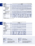
Comparison of some key features of the Intel Xeon Processor E7-8800/4800/2800
Product Families, and Intel® Xeon® Processor 7500 series are listed in Table 2-1.
Table 2-1.
Intel® Xeon® Processor E7-8800/4800/2800 Product Families and Intel®
Xeon® Processor 7500 Series Key Features (Sheet 1 of 2)
Intel® Xeon®
Processor 7500
Series
Features
Intel® Xeon®
Processor E78800/4800/2800
Product Families
Comments
Number of cores/threads per core
8/2
10/2
Total of 20 threads
Lowest-Level Cache (LLC)
24 MB
30 MB
Inclusive shared cache
Physical Address
44 bits
Intel QuickPath Interconnect
speeds
4.8/5.86/6.4 GT/s
4.8/5.86/6.4 GT/s
Two high-performance
connectors, plus maximum
of 17" FR4 trace length
Memory Speed
DDR3-800, DDR3978, DDR31067 MHz
DDR3-800, DDR3978, DDR31067 MHz
Power Delivery
PTP
PTP
Power-Through-the-Pins
Power TDP
130W, 105W, 95W
130 W, 105W, 95W
ACPI states
C0, C1, C1e, C3,
P-State
S0/S4
C0, C1, C1E, C3, C6
P-State S0/S4
C1: halt, All cores halted;
V/f scale to min. voltage,
C3, C6
Caching agents per socket
2
2
Each caching agent handles
1/2 of the address space
Datasheet Volume 2 of 2
13
Intel Xeon Processor E7-8800/4800/2800 Product Families Architecture
Table 2-1.
Intel® Xeon® Processor E7-8800/4800/2800 Product Families and Intel®
Xeon® Processor 7500 Series Key Features (Sheet 2 of 2)
Intel® Xeon®
Processor 7500
Series
Features
2.1.1
Intel® Xeon®
Processor E78800/4800/2800
Product Families
Comments
LLC error protection
DECTED on Data
DECTED on Data
Node ID bits supported
5
5
SECDED on Tags
Node IDs used per socket
3
3
Home/Caching agent 01,
11, and Ubox 10
Bbox tracker entries
256
256
Maximum HA tracker
entries
DCA
yes
yes
Direct cache access via
PrefetchHint
SCA
yes
yes
Standard Configuration
Architecture
OOB interface
PECI
PECI
Out-of-Band Interface
Intel® Xeon® Processor 7500 Series-Based Platform
Overview
Figure 2-1 provides a Intel® Xeon® Processor 7500 Series-Based platform overview of
a fully connected four-socket, two-IOH configuration. Each Intel Xeon Processor E78800/4800/2800 Product Families are connected to every other Intel Xeon Processor
E7-8800/4800/2800 Product Families socket using three of the Intel QuickPath
Interconnects. This enables each Intel Xeon Processor E7-8800/4800/2800 Product
Families to be one link hop from each other and enables the support of a two-hop
snoop protocol. The fourth Intel QuickPath Interconnect is used to connect to an IO
Hub (IOH).
Figure 2-1.
Intel® Xeon® Processor 7500 Series-Based Platform Block Diagram, Foursocket Two-IOH Configuration
Intel® Xeon®
Processor E78800/4800/2800
Product Families
Intel® Xeon®
Processor E78800/4800/2800
Product Families
IOH
14
Intel® Xeon®
Processor E78800/4800/2800
Product Families
Intel® Xeon®
Processor E78800/4800/2800
Product Families
IOH
Datasheet Volume 2 of 2
Intel Xeon Processor E7-8800/4800/2800 Product Families Architecture
2.2
Intel Xeon Processor E7-8800/4800/2800
Product Families Components (Boxes)
The Intel Xeon Processor E7-8800/4800/2800 Product Families consist of ten Intel Xeon
Processor E7-8800/4800/2800 Product Families cores connected to a shared, 30-MB
inclusive, 30-way set-associative Last-Level Cache (LLC) by a high-bandwidth
interconnect. The cores and shared LLC are connected via caching agents (Cbox) and
system interface (Sbox) to the Intel QuickPath Interconnect router (Rbox), the on-chip
Intel QuickPath Interconnect home agents and memory controllers (Bboxes + Mboxes),
and the system configuration agent (Ubox). The Rbox is a general-purpose Intel
QuickPath Interconnect router that connects cores to the Bboxes, the four external
Intel QuickPath Interconnects (through the pad controllers, or Pboxes), and the system
configuration agent (Ubox), through the Sboxes. The Ubox shares an Rbox port with
one of the Bboxes.
With respect to the Intel QuickPath Interconnect specification, Sboxes and Bboxes
collectively implement the Intel QuickPath Interconnect Protocol layer (caching agent
and home agent sides, respectively). The Rbox functions as both an Intel QuickPath
Interconnect Layer agent and an Intel QuickPath Interconnect Routing agent. The Ubox
is used as the Intel Xeon Processor E7-8800/4800/2800 Product Families Intel
QuickPath Interconnect Configuration Agent and participates in many of the noncoherent Intel QuickPath Interconnect Protocol flows. The Intel QuickPath Interconnect
Physical layer is implemented by the Pbox.
Each core is connected to the un-core interconnect through a corresponding Caching
agent. The Cbox is both the interface to the core interconnect and a last-level cache
bank. The Cboxes can operate in parallel, processing core requests (reads, writes,
writebacks) and external snoops, and returning cached data and responses to the cores
and Intel QuickPath Interconnect system agents. The Intel Xeon Processor E7-8800/
4800/2800 Product Families implement a bypass path from the Sbox to the
corresponding Bbox to reduce the memory latency for requests targeting memory
addresses mapped by that Bbox. When configured in “hemisphere” mode, the Bbox will
only map addresses corresponding to the corresponding Sbox in this and other sockets.
If the system or applications are NUMA (non-uniform memory access) optimized, the
cores on this socket will mostly access the memory on this socket. Combining NUMA
optimizations and hemisphering results in most memory requests accessing the Bbox
that is directly connected to the requesting Sbox, minimizing memory latency.
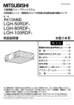
Figure 2-2 provides a Intel Xeon Processor E7-8800/4800/2800 Product Families block
diagram.
Datasheet Volume 2 of 2
15
Intel Xeon Processor E7-8800/4800/2800 Product Families Architecture
Figure 2-2.
Intel® Xeon® Processor E7-8800/4800/2800 Product Families Block Diagram
Core
1
Core
2
Core
3
Core
4
Core
5
Cbox
Core
6
Core
7
Core
8
Core
9
Core
10
(LLC Coherence Engine)
30M Last Level Cache (L3 Cache)
Dual Intel ® SMI
Channels
Pbox
(Physical
Layer)
Sbox
Sbox
(Caching Agent 1)
(Caching Agent 2)
Mbox
Bbox
(Memory
Controller)
(Home
Agent 1)
Wbox
(Power Controller)
Rbox
(Router)
Dual Intel ® SMI
Channels
Bbox
Mbox
(Home
Agent 2)
(Memory
Controller)
Pbox
Pbox
Pbox
Pbox
Ubox
(Physical
Layer)
(Physical
Layer)
(Physical
Layer)
(Physical
Layer)
(System Config
Controller)
Pbox
(Physical
Layer)
4 Intel® QPI links
Table 2-2.
System Interface Functional Blocks
Name
Function
Core
Intel Xeon Processor E7-8800/4800/2800 Product Families core
architecture processing unit
Bbox
Home Agent
Cbox
Last Level Cache Coherency Engine
Mbox
Integrated Memory Controller
Pbox
Physical Layer (PHY) for the Intel® QPI Interconnect and Intel® SMI
Interconnect memory controller
Rbox
Crossbar Router
Sbox
Caching Agent
Ubox
System Configuration Agent
Wbox
Power Controller
Intel® SMI
Intel® Scalable Memory Interconnect (formerly “FBD2” or “Fully
Buffered DIMM 2 interface”)
Intel® QPI
Intel® QuickPath Interconnect
LLC
Last Level Cache (Level 3)
§
16
Datasheet Volume 2 of 2
Address Map
3
Address Map
3.1
NodeID Generation
Intel Xeon processor 7500 series system addresses are made up of a socket and a
device within the socket. With a 5-bit NodeID in the Intel QuickPath Interconnect SMP
profile, Intel Xeon processor 7500 series can support up to four sockets (chosen by
NID[3:2] when NID[4] is zero). Within each socket are four devices (NID[1:0]): IOH
(00), B0/S0 (01), Ubox (10), B1/S1 (11). The IOH is the chipset; B0/S0 and B1/S1 are
two sets of home agents (Bboxes) and caching agents (Sboxes); the Ubox is the
configuration agent.
3.1.1
DRAM Decoder
There are four node assignment methods implemented for the DRAM Decoder. In each
method, three target list index bits are used to look up NID bits [4:1] from an 8-entry
4-bit target list. Two modes use mixed address bits (when tgtsel is 0). Two modes use
low-order address bits (when tgtsel is 1). Table 3-1 shows which address bits are used
for the target list index, based on the value of tgtsel.
Table 3-1.
Target List Index
Mode
tgtsel
tgtidx[2]
tgtidx[1]
tgtidx[0]
Mixed
0
addr[8] ^ addr[18]
addr[7] ^ addr[17]
addr[6] ^ addr[16]
Low-order
1
addr[8]
addr[7]
addr[6]
Based on the value of tgtidx[2:0], a four bit value listnid[4:1] is selected from
tgtlist[31:0] as follows:
• listnid[4] = tgtlist[{tgtidx[2:0], 2b'11}]
• listnid[3] = tgtlist[{tgtidx[2:0], 2b'10}]
• listnid[2] = tgtlist[{tgtidx[2:0], 2b'01}]
• listnid[1] = tgtlist[{tgtidx[2:0], 2b'00}]
The value of listnid[4:1] is used in conjunction with the hemisphere bit (cboxid[2]), and
idbase (from the array payload) to form NID[4:0] according to Table 3-2. Note that
cboxid[2] is logically XOR'ed into this calculation in the implementation, so if listnid[1]
is not used in a particular mode, it should be set to zero in the payload.
Table 3-2.
NodeID Formation
Mode
hemi
NID[4]
NID[3]
NID[2]
NID[1]
NID[0]
Home
0
listnid[4]
listnid[3]
listnid[2]
listnid[1]
idbase
Socket
1
listnid[4]
listnid[3]
listnid[2]
listnid[1] ^cboxid[3]
idbase
Using socket-level interleaving is known as "hemisphere mode". This requires that
Bboxes on the same socket have identical memory configurations. In this model, the
number of CAs which talk to a particular Bbox is reduced from 32 (in a four-socket
system) to 16. This allows each CAs to use up 48 tracker entries in each Bbox. In order
to use this model, external agents (that is, IOHs and XNCs) must understand how the
interleaving between "even" and "odd" Bboxes is done, which is generated from the
address by the Intel Xeon processor 7500 series hash function.
Datasheet Volume 2 of 2
17
Address Map
3.1.2
I/O Decoder Map
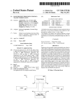
Table 3-3 shows the I/O decoder address map. Given for each region are the name, the
pattern for address bits [31:14], the size in bytes, the memory attribute, the number
of targets in the target list, the address bits used to index the target list (if any), which
CSR is used to enable the entry, and the location (decoder and entry number). For all
regions which specify an address pattern, address bits [43:32] must be zero to match,
except those marked with "*". Also, any address in the 4 GB – 64 MB...4 GB range will
be forced to mismatch any region, except for those fixed to that range. In other words,
any address in this range which would otherwise match the MMIOL1 entry or a DRAM
decoder entry is forced to mismatch. The CFG entries are not allowed to overlap the 4
GB – 64 MB...4 GB range.
Table 3-3.
I/O Decoder Entries (Sheet 1 of 2)
Name
CFG
Addr[31:14]
Size
Attr
Tgts
Index
Enable
Entry
aaaa_xxxx_xxxx_xxxx_xx
256 MB
CFG
8
[27:25]
IOMMEN
IOL0
CFG-SCA
aaaa_bbbb_bccc_xxxx_xx
8 MB
CFG
8
[22:20]
IOMMEN
IOS0
MMIOL0
dddd_xxxx_xxxx_xxxx_xx
2 GB
MMIO
8
[30:28]
IOMMEN
IOL1
MMIOL1
eeee_xxxx_xxxx_xxxx_xx
2 GB
MMIO
8
[30:28]
IOMMEN
IOL2
VGA
0000_0000_0000_101x_xx
128 KB
MMIO
1
N/A
CSEGEN
IOS1
BIOS
0000_0000_0000_11ff_ff
256 KB
MMIO
1
N/A
BIOSEN
IOS8
CPU Cfg
1111_1100_xxxx_xxxx_xx *
16 MB
MMIO
8
[23:21]
IOVLD
IOL3
Local clump
CPU Cfg
1111_1100_bccc_bbbb_xx *
512KB1
MMIO
8
[22:20]
IOMMEN
IOVLD
IOS9
IOH Cfg
1111_1101_xxxx_xxxx _xx *
16 MB
MMIO
8
[23:21]
IOVLD
IOL4
Local Config.
1111_1110_1011_xxxx_xx *
1 MB
MMIO
1
N/A
always
IOS3
IOAPIC
1111_1110_1100_xxxx_xx
1 MB
MMIO
8
[15:13]
IOVLD
IOL5
ICH
1111_1110_1101_xxxx_xx
1 MB
MMIO
1
N/A
IOVLD
IOS2
FWH
1111_1111_xxxx_xxxx_xx
16 MB
MMIO
8
[23:21]
IOVLD
IOL6
Legacy I/O
0000_0000_0000_0000_xx +
64 KB
IO
8
[15:13]
IOVLD
IOL7
CFG
1000_xxxx_xxxx_xxxx_xx +
256 MB
CFG
8
[27:25]
IOVLD
IOL0
CFG-SCA
1000_bbbb_bccc_xxxx_xx +
8 MB
CFG
8
[22:20]
IOMMEN
IOS0
Used for LT
match
1111_1110_1101_xxxx_xx +
1-4 Byte, 8
Byte (IO
access)
64 Byte (Mem
type access)
LT
Leg
IOH
N/A
always
IOS10
LT Doorbell
0xFED20EXX
1-4 Byte
8 Byte
LT
Leg
IOH
N/A
always
IOS11
IntA
N/A
N/A
N/A
1
N/A
always
IOS5
Lock
N/A
N/A
N/A
1
N/A
always
IOS6
SplitLock
N/A
N/A
N/A
1
N/A
always
IOS6
Unlock
N/A
N/A
N/A
1
N/A
always
IOS6
Shutdown
N/A
N/A
N/A
1
N/A
always
IOS5
Invd_Ack
N/A
N/A
N/A
1
N/A
always
IOS6
WbInvd_Ack
N/A
N/A
N/A
1
N/A
always
IOS6
RSVD_Debug
N/A
N/A
N/A
1
N/A
always
IOS7
DbgWr
N/A
N/A
N/A
1
N/A
always
IOS7
IntPriUp
N/A
N/A
N/A
1
N/A
always
IOS6
18
Datasheet Volume 2 of 2
Address Map
Table 3-3.
I/O Decoder Entries (Sheet 2 of 2)
Name
Addr[31:14]
Size
Attr
Tgts
Index
Enable
Entry
IntLog
N/A
N/A
N/A
1
N/A
always
IOS6
IntPhy
N/A
N/A
N/A
1
N/A
always
IOS6
EOI
N/A
N/A
N/A
1
N/A
always
IOS6
FERR
N/A
N/A
N/A
1
N/A
always
IOS5
Notes:
1.
Non-contiguous
In the Addr field, letters have the following meaning:
• "x...x": match any value
• "aaaa": match if equal to IOMMEN cfg_base field
• "bbbbb": match if equal to IOMMEN sca_clump field
• "ccc": match if corresponding IOMMEN sca_ena bit is set
• "dddd": match if greater than IOMMEN cfg_base and Addr[31] = 0
• "eeee": match if greater than IOMMEN cfg_base and Addr[31] = 1; prevent match
when Addr[31:26] = 111111
• "ffff": match if the BIOSEN r/w enable bit is set for the corresponding segment, for
reads and writes, respectively
• "*" means that Addr[43:32] = 0x000 always matches, and Addr[43:32] = 0xFF0
matches in SMM mode
• "+" means that the address is in the I/O address space, separate from the memory
address space
Target lists are needed for the CFG, MMIOL0/1, CPU/IOH Cfg, IOAPIC, FWH, and
Legacy I/O regions. These entries make up the I/O Large (IOL) Decoder. The reasons
for the existence of target lists for these regions are described in the following table.
3.2
Intel® Trusted Execution Technology (Intel® TXT)
Intel® Trusted Execution Technology (Intel® TXT) is a component of the Intel® Safer
Computing Initiative (Intel® SCI). Intel® TXT was first introduced in client platforms.
Intel TXT for Servers is an effort to extend Intel® TXT into server platforms. Intel® TXT
for Servers is a software binary compatible with Intel® TXT and uses a security model
that allows the RAS features to co-exist with security. To achieve this objective, some
of the system firmware is allowed to be within the trust boundary.
Intel® TXT provides an architected process to measure the BIOS and measured launch
environment (for example, VMM or OS) before launch.
3.2.1
Key Concepts
• Intel® TXT is a family of security capabilities now available on server platforms.
• Intel® TXT uses features in the processors, chipset, BIOS, and TPM to enable more
secure platforms.
• Intel® TXT works through measurement, dynamic launch mechanisms via special
instructions, memory locking and sealing secrets.
• Intel® TXT helps detect and/or prevent software attacks.
Datasheet Volume 2 of 2
19
Address Map
— Attempts to insert non-trusted VMM (rootkit hypervisor) Reset attacks designed
to compromise platform secrets in memory
— BIOS and firmware update attacks
§
20
Datasheet Volume 2 of 2
LLC Coherence Engine (Cbox) and Caching Agent (Sbox)
4
LLC Coherence Engine (Cbox)
and Caching Agent (Sbox)
The Intel Xeon Processor E7-8800/4800/2800 Product Families core to the last level
cache (LLC) interface is managed by the LLC coherence engine (Cbox). All Intel Xeon
Processor E7-8800/4800/2800 Product Families core to Intel QuickPath Interconnect
messages are handled through the Cbox and system interface logic. The Intel Xeon
Processor E7-8800/4800/2800 Product Families contain ten instances of the Cbox, each
managing 3 MB of the 30 MB LLC. Five instances of the Cbox, C0-C4, are associated
with the Sbox 0, and C5-C9 are associated with Sbox 1.
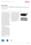
Figure 4-1 provides a Intel Xeon Processor E7-8800/4800/2800 Product Families block
diagram including Cbox and Sbox.
Figure 4-1.
Intel Xeon Processor E7-8800/4800/2800 Product Families Block Diagram
Core
1
Core
2
Core
3
Core
4
Core
5
Cbox
Core
6
Core
7
Core
8
Core
9
Core
10
(LLC Coherence Engine)
30M Last Level Cache (L3 Cache)
Dual Intel® SMI
Channels
Sbox
Sbox
(Caching Agent 1)
(Caching Agent 2)
Pbox
Mbox
Bbox
(Physical
Layer)
(Memory
Controller)
(Home
Agent 1)
Wbox
(Power Controller)
Rbox
(Router)
Dual Intel® SMI
Channels
Bbox
Mbox
Pbox
(Home
Agent 2)
(Memory
Controller)
(Physical
Layer)
Pbox
Pbox
Pbox
Pbox
Ubox
(Physical
Layer)
(Physical
Layer)
(Physical
Layer)
(Physical
Layer)
(System Config
Controller)
4 Intel® QPI links
4.1
Last Level Cache
The 30 MB Last Level Cache (LLC) consists of ten 3 MB slices and are addressed via an
address hash function. This function is designed to evenly distribute accesses among
the cache slices, even if the access pattern is a regular stride. It is also designed to
evenly distribute accesses among the sets (indexes) of each slice.
Datasheet Volume 2 of 2
21
LLC Coherence Engine (Cbox) and Caching Agent (Sbox)
4.1.1
LLC Major Features
• Cache size:
— 30 MB for ten Intel Xeon Processor E7-8800/4800/2800 Product Families
core topologies
• Organization:
— Associativity: 24 ways
— Line Size: 64 Bytes
• Protection:
— DECTED ECC for the data array
— SECDED ECC correct for the tag array
— SECDED ECC protection for the core valid array
— SECDED ECC protection for the LRU array
4.2
RTID Generation
The Cboxes associated with one Sbox have either 16, 24, 32, 48 or 64 RTIDs to divide
among themselves for HOM requests. In order to do this, each Cbox will have a
particular length for all freelists, and one base RTID to add to the priority-encoded
value from the selected freelist. Depending on the configuration (10 LLC, 8 LLC, 6 LLC,
or 4 LLC cache slices), Table 4-1, Table 4-2, and Table 4-3 specify how the freelist
lengths and base RTIDs are programmed for the 5, 4, 3, or 2 Cboxes associated with
each Sbox respectively.
Table 4-1.
RTID Generation 10 LLC (Last Level Cache) Slices
Sbox RTIDs
Table 4-2.
Freelist Lengths
16
4, 3, 3, 3, 3
0, 4, 7, 10, 13
24
6, 6, 4, 4, 4 or
5, 5, 5,5, 4
0, 6, 12, 16, 20
32
7, 7, 6, 6, 6,
0, 7, 14, 20, 26
48
10, 10, 10, 9, 9
0, 10, 20, 30, 39
64
12, 12, 12, 12, 12
0, 12, 24, 36, 48
RTID Generation 8 LLC (Last Level Cache) Slices
Sbox RTIDs
22
Base RTIDs
Freelist Lengths
Base RTIDs
16
4, 4, 4, 4
0, 4, 8, 12
24
6, 6, 6, 6
0, 6, 12, 18
32
8, 8, 8, 8
0, 8, 16, 24
48
12, 12, 12, 12
0, 12, 24, 36
64
12, 12, 12, 12
0, 12, 24, 36
Datasheet Volume 2 of 2
LLC Coherence Engine (Cbox) and Caching Agent (Sbox)
Table 4-3.
RTID Generation 6 LLC (Last Level Cache) Slices
Sbox RTIDs
Note:
Freelist Lengths
Base RTIDs
16
6, 5, 5
0, 6, 11
24
8, 8, 8
0, 8, 16
32
11, 11, 10
0, 11, 22
48
12, 12, 12
0, 12, 24
64
12, 12, 12
0, 12, 24
During power-on before Non-coherent (NC) freelist is available and programmed, only
one RTID is available and core is not expected to get into C6 unless freelist is
programmed.
NC RTID/freelist can be defeatured to minimum 3 in Intel Xeon Processor 7500 Series
(1st for NC victim, 2nd is required for making sure lock is sent out, 3rd one shared for
any other request), and minimum 4 in Intel Xeon Processor E7-8800/4800/2800
Product Families (4th one is required to make sure VN1 make progress).
MAF can be defeatured to minimum 5 in Intel Xeon Processor E7-8800/4800/2800
Product Families, SRT req table entry can be minimum 5 in maf_reserve defeature
mode.
§
Datasheet Volume 2 of 2
23
LLC Coherence Engine (Cbox) and Caching Agent (Sbox)
24
Datasheet Volume 2 of 2
Home Agent and Global Coherence Engine (Bbox)
5
Home Agent and Global
Coherence Engine (Bbox)
Each Intel Xeon Processor E7-8800/4800/2800 Product Families home agent integrates
a global coherence engine that is the center of the coherency activity for the cache
lines owned by that home agent. The Bboxes receive Home channel request and snoop
responses from caching agents, and provides data response and completion to the
system via Bbox to Router connection. Read and write commands to memory go out of
the Bbox to the Memory Controller (MBox).
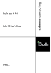
Figure 5-1 provides a Intel Xeon Processor E7-8800/4800/2800 Product Families block
diagram including the Bbox.
Figure 5-1.
Intel Xeon Processor E7-8800/4800/2800 Product Families Block Diagram
Core
1
Core
2
Core
3
Core
4
Cbox
Core
5
Core
6
Core
7
Core
8
Core
9
Core
10
(LLC Coherence Engine)
30M Last Level Cache (L3 Cache)
Dual Intel ® SMI
Channels
Pbox
(Physical
Layer)
Sbox
Sbox
(Caching Agent 1)
(Caching Agent 2)
Mbox
Bbox
(Memory
Controller)
(Home
Agent 1)
Wbox
(Power Controller)
Rbox
(Router)
Dual Intel ® SMI
Channels
Bbox
Mbox
(Home
Agent 2)
(Memory
Controller)
Pbox
Pbox
Pbox
Pbox
Ubox
(Physical
Layer)
(Physical
Layer)
(Physical
Layer)
(Physical
Layer)
(System Config
Controller)
Pbox
(Physical
Layer)
4 Intel® QPI links
5.1
Tracker Allocation Modes
The tracker table keeps track of coherency state at the home node for each transaction
in-flight in the system (that has touched the home node). For each transaction that a
caching agent injects into the system a tracker entry was statically preallocated at the
home. The tracker allocation mode determines the particular preallocation during
system initialization. The tracker allocation mode determines this statical partitioning of
the tracker entries across the caching agents (Sboxes, IOHs, XNCs). There is a one-toone correspondence between a Transaction ID (TID) originating from a particular
caching agent (Node ID=NID) and a tracker entry. In effect, each of the 256 tracker
entries is statically mapped to a Transaction ID (TID), Node ID (NID) couple and viceversa.
Datasheet Volume 2 of 2
25
Home Agent and Global Coherence Engine (Bbox)
5.1.1
The Tracker Modes
The tracker modes (0..3) are specifically chosen to support systems consisting of 4
gluelessly connected Intel Xeon Processor E7-8800/4800/2800 Product Families
sockets and 2, 4 IOH/XNC nodes (IOH = I/O Hub, XNC = eXternal Node Controller).
Minimal support is also provided for 8 IOH/XNCs. Mode 5 has been added to support
glueless 8 Intel Xeon Processor E7-8800/4800/2800 Product Families sockets and 4
IOH nodes. In general, 32 entries per IOH/XNC are supplied to mitigate bandwidth
restrictions for the long latency operations typically associated with these nodes
(except for the 8 IOH/XNCs configuration).
The supported tracker modes are listed in Table 5-1.
Table 5-1.
Tracker Allocation Modes
Mode
Note:
Sboxes x #Entries,
NID Assignment
Purpose
IOH/XNCs x #Entries, NID
Assignment
0
4S HemiSphere + 4 IOH/XNC
4 x 32, 0YZH1*
4 x 32, 0/1YZ00
1
4S HemiSphere + 2 IOH/XNC
4 x 48, 0YZH1
2 x 32, 0/10Z00
2
4S Non-HemiSphere + 2 IOH/XNC
8 x 24, 0YZH1
2 x 32, 00Z00
3
4S Non-HemiSphere + 4 IOH/XNC
8 x 16, 0YZH1
4 x 32, 0YZH1
4
8S HemiSphere + 4IOH/XNC
2X48+ 6X16,
XYZ01 -->Sbox0
XYZ11
4x16, 0XY00
5
8S HemiSphere + 4IOH/XNC
4x32+4x16, XYZH1
4x16, 0YZ00
6
4S Hemisphere + 2 IOH/XNC
1 X 64 + 3 X 32,
0XY01 -->Sbox0
0XY11 -->Sbox1
2 x 32,
0XY00 (XY cant be '11)
7
4S Non-Hemisphere + 2 IOH/XNC
2 X 32 + 6 X 16
0XY01 -->Sbox0
0XY11 -->Sbox1
2 x 32,
0XY00 (XY cant be '11)
Tracker Modes 6 and 7 are new, and Tracker Mode 4 has been updated for the Intel
Xeon Processor E7-8800/4800/2800 Product Families.
• Some NID bits have to be zero or one.
• XNC NID assignment follows IOH’s NID, with NID<4> set 1.
• * H corresponds to the co-located Sbox.
• In Hemisphere mode, nodeID<1> in the SAD target lists XORed with the
hemisphere number (0 or 1) and is normally zero.
• Changes to the tracker mode should only be made when the system is quiesced.
Table 5-2.
TID Assignment Restrictions (Sheet 1 of 2)
Mode
26
Configuration
Sboxes
IOH/XNCs
0
4S HemiSphere + 4 IOH/XNC
TID [0...31]
1
4S HemiSphere + 2 IOH/XNC
TID [0...47]
TID [0...31]
2
4S Non-HemiSphere + 2 IOH/XNC
TID [0...23]
TID [0...31]
3
4S Non-HemiSphere + 4 IOH/XNC
4
8S Hemisphere + 4 IOH/XNC
TID [0...15]
TID [0...31]
[0…47], [0…15]
TID [0...15]
Datasheet Volume 2 of 2
Home Agent and Global Coherence Engine (Bbox)
Table 5-2.
TID Assignment Restrictions (Sheet 2 of 2)
Mode
5
Configuration
8S HemiSphere + 4 IOH/XNC
Sboxes
IOH/XNCs
TID [0...31],TID[0..15]
TID [0...15]
6
4S Hemisphere + 2 IOH/XNC
TID [0…63], TID [0…31]
TID [0...31]
7
4S Non-Hemisphere + 2 IOH/XNC
TID [0…31], TID [0…15]
TID [0...31]
Note:
TID Assignment Restrictions have been updated for modes 4, 5, 6, and 7.
5.2
Directory Assisted Snoopy (DAS)
DAS stands for Directory Assisted Snoopy. It enables early data return from Home
(BBox) to Requestor (Caching agent), without waiting for peer snoop responses if
directory state for the requested line indicates that no peer socket has the line. DAS is
enabled only for local socket request. For enabling DAS (for local socket) we have
introduced a new directory state known as Remote State (or R state). Intel Xeon
processor 7500 series only had two directory states namely I state (Idle state) or E
state (owned by IOH). In Intel Xeon Processor E7-8800/4800/2800 Product Families, R
state is also introduced. These 3 state are defined in Intel Xeon Processor E7-8800/
4800/2800 Product Families as:
• I state: Line is either not present in any caching agent or is owned by local socket
caching agent, but definitely not present in any remote socket/IOH.
• R state: Line may be present in a remote socket.
• E (or D) state: Line is owned by IOH.
If DAS is enabled and local socket sends a read request (RdData/RdInvown), BBox
does a MemRead (basically a prefetch) and directory bits (received with prefetch ack
from Mbox) indicates I state, then data can be send to the requesting local socket even
before all the peer snoop responses have been received. DAS is a very significant
performance feature for 8 socket systems and NC based topologies which are limited
by snoop bandwidth (that is, where idle read latency is snoop limited and not Memory
latency limited).
DAS is only supported in hemisphere mode and not in non-hemisphere mode.
DAS is not supported with mirroring.
5.3
IO Directory Cache (IODC)
IO Directory Cache (IODC) is a new feature for Intel Xeon Processor E7-8800/4800/
2800 Product Families. The aim of this feature is to improve Streams throughput by
eliminating directory reads for InvItoE from snoopy caching agents.
We Implement a 64 entry directory cache to complement directory in memory.
This feature leverages 2 IOH properties:
• IOH can only get ownership of a line via InvItoE.
• IOH can only own as many lines as it has RTIDs.
IOH takes ownership of the line by issuing an InvItoE. This exclusive ownership phase
(started by IOH issuing an InvItoE and ends in BBox sending GntE_CMP) is almost
immediately followed by WriteBack Phase.
Datasheet Volume 2 of 2
27
Home Agent and Global Coherence Engine (Bbox)
IODC is supported only in 4 socket configurations with 2 IOH or less. It is also not
supported with 8 socket tracker modes 4 and 5.
IODC and DAS features are orthogonal. They can not be supported together.
DAS targets memory latency improvements for snoop bound topologies and IODC
targeting streams memory bandwidth improvement. 4/2 sockets topologies are not
expected to benefit from DAS since the latency is memory bound. Similarly streams
bandwidths for 8 socket topologies are limited by Intel QPI utilization and are unlikely
to improve with IODC.
Also DAS feature is beneficial for 8 socket topology where snoop latency is the
bottleneck and IODC feature is beneficial for 4 socket topologies where memory
bandwidth is a bigger concern.
All inter-socket mirroring configurations will need to disable IODC.
§
28
Datasheet Volume 2 of 2
System Configuration Controller (Ubox)
6
System Configuration
Controller (Ubox)
The Intel Xeon Processor E7-8800/4800/2800 Product Families contain a system
configuration controller (Ubox).
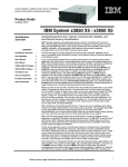
Figure 6-1 provides a Intel Xeon Processor E7-8800/4800/2800 Product Families block
diagram including the Ubox.
Figure 6-1.
Intel Xeon Processor E7-8800/4800/2800 Product Families Block Diagram
Core
1
Core
2
Core
3
Core
4
Cbox
Core
5
Core
6
Core
7
Core
8
Core
9
Core
10
(LLC Coherence Engine)
30M Last Level Cache (L3 Cache)
Dual Intel® SMI
Channels
Pbox
(Physical
Layer)
Sbox
Sbox
(Caching Agent 1)
(Caching Agent 2)
Mbox
Bbox
(Memory
Controller)
(Home
Agent 1)
Wbox
(Power Controller)
Rbox
(Router)
Dual Intel® SMI
Channels
Bbox
Mbox
(Home
Agent 2)
(Memory
Controller)
Pbox
Pbox
Pbox
Pbox
Ubox
(Physical
Layer)
(Physical
Layer)
(Physical
Layer)
(Physical
Layer)
(System Config
Controller)
Pbox
(Physical
Layer)
4 Intel® QPI links
6.1
Introduction
The Ubox is a system configuration agent organized as a number of modular utilities.
Some of the different utilities include Intel SMI, scratch registers, test and set
registers, Flash ROM interface, CSR bridge, interval timer, VLW, Lock, exception, and
interrupts. It receives and sends Intel QuickPath Interconnect transactions to the rest
of the local Intel Xeon Processor E7-8800/4800/2800 Product Families and through the
Rbox port shared with a Bbox.
§
Datasheet Volume 2 of 2
29
System Configuration Controller (Ubox)
30
Datasheet Volume 2 of 2
Memory Controller (Mbox)
7
Memory Controller (Mbox)
The Intel Xeon Processor E7-8800/4800/2800 Product Families consists of two
integrated memory controllers. The memory controller (Mbox) contains the interface
logic to Intel 7500 Scalable Memory Buffer via Intel SMI interface (formerly “Fully
Buffered DIMM 2 interface”). Mbox issues memory read and write commands per Intel
SMI protocol and schedules them with respect to DDR III timing. The other main
function of the memory controller (Mbox) is the generating and checking of advanced
ECC.
Each memory controller (Mbox) supports two Intel SMI channels, for a total of 4 Intel
SMI channels per socket. One Mbox supports a pair of channels operating in lock-step.
This minimizes latency and more importantly enables x8 DDDC. Minimum transfer
burst of four ticks in DDR3 support for burst length 4 mode (BL4).
7.1
New Features on Intel Xeon Processor E7-8800/
4800/2800 Product Families
• 32 GB DIMM support
• Intel®x4 Double Device Data Correction (DDDC)
7.2
Memory Controller (Mbox) Support
• DDR3 protocol, with operating DDR frequency of 800-1067
• 4 ticks burst mode (8 ticks burst mode not supported)
• 1 GB to 32 GB DIMM
• 1-Gb, 2-Gb, and 4 Gb (x4 and x8) devices
• Single, dual and Quad-rank DIMM support
• Minimum size of 2 GB per Mbox (2 channels, 1 DIMM per channel, 1 Gb x8 devices,
single rank DIMMs=1 GB DIMMs)
• Support for four and eight banks
• Supports two Intel SMI channel channels operating in lockstep. Each Intel SMI
channel is connected to a Intel 7500 Scalable Memory Buffer (Intel SMI-DDR3
bridge).
• A maximum of 32 ranks per locked-step pair of Intel SMI links. (16 ranks per Intel
SMI channel).
• Mixing of DIMM types is allowed (with a maximum of four types per channel) as
long as each of the two lock-stepped channels are populated identically.
— No variable latency access within an Intel SMI channel is supported. The
latency of all DIMMs is equalized to the latency of the last DIMM.
• Maximum eight DIMMs per memory controller. (Four DIMMS per Intel 7500
Scalable Memory Buffer.)
• Double Device Data Correction (DDDC) is only supported for DIMMs with X4
devices. Single Device Data Correction (SDDC) is supported for both X4 and X8
devices. Also, all ranks will need to default to SDDC if there is a mix of X4 and X8
DIMMs behind a memory controller
Datasheet Volume 2 of 2
31
Memory Controller (Mbox)
Note:
Memory Mirroring with tracker mode 6 is not supported.
Note:
RFR_FSM errors may be logged in the Mbox while in 2x refresh.
7.3
Double Device Data Correction (DDDC)
DDDC (Double Device Data Correction) is a feature which assures data availability after
hard failure of 2 x4 DRAM’s.
Supports x4 DDDC plus an additional single bit error correction.
7.3.1
DDDC flow overview
• One x4 DRAM device in each rank is reserved as spare device.
• ECC code has parity nibble instead of parity byte. This way DDDC ECC code has 16
bits of parity instead of 32 bits in regular ECC code.
• When first device failure is detected, content of failing/failed device gets read,
corrected, and then written back in spare device.
• When second device failure is detected, the failed device number is logged and
regular device recovery process is followed.
7.3.2
DDDC Constraints
• DDDC can be enabled by BIOS only and only if x4 DIMMs are populated behind the
memory controller. If x4 and x8 DIMMs are mixed together, DDDC should be
disabled.
• Double strike errors are not corrected when DDDC is enabled.
• DDDC should be disabled on memory controller that is a Mirror Master.
7.4
Leaky Bucket Error Counters
This feature is to make the error counters counting the more transient errors, to be
more accurate. The counters which are selected to be leaky bucket in nature are given
below with the reasoning.
7.4.1
Per Rank Memory Error Counter
This counter counts the DRAM errors per rank.There are possibilities for this counter to
count transient errors as memory errors. To make it accurate we can make them as
leaky bucket counters.
7.4.2
Error Flow Counters
• SB soft reset flow, SB Fast reset flow, NB Transient error, NB soft reset flow, NB
Fast reset flow counters.
• These counters count the number of time each flow is run and how consistent they
are. For example, NB soft reset flow is consistent it triggers NB fast reset flow. If
NB fast reset flow is consistent it declares lane dead.
• To make these consistency check very accurate, currently an nearly leaky bucket
kind of counter is implemented. That can be converted as regular leaky bucket
counters.
32
Datasheet Volume 2 of 2
Memory Controller (Mbox)
7.5
Partial Memory Mirroring
Partial memory mirroring is a mirror mode of operation with parts of system memory
operating with redundant memory at slave, leaving the rest of the system memory in
non-mirror mode. The granularity of the partial memory that gets to operate in mirror
mode is implementation dependent. On the Intel Xeon Processor E7-8800/4800/2800
Product Families, the granularity is defined to be at the Home Agent level, meaning
either all of the memory behind the Home Agent is mirrored or it is not.
Partial Memory Mirroring provides additional flexibility to the platform to optimize cost/
performance/RAS by providing higher degree of reliability to memory segment that is
deemed to be containing the most critical content, at lower cost than mirroring the
entire system memory.
7.5.1
Usage Model
Memory Mirroring is a RAS feature that enables duplicating memory content at a
remote DIMM in the partition. This capability enables high data availability from
memory subsystem, which due to its large cell array, is prone to various error types.
Partial Memory Mirroring enables you to select the segments of system memory that
will be containing the most critical code, that is, Kernel codes, to operate with higher
degree of reliability than the rest of the data. OEM will need to have control over the OS
to load the critical code/data into the mirrored memory region. This form of partial
mirror configuration is done statically at power up, with no dynamic readjustment to
the configuration. This usage model is enabled for the Intel Xeon processor 7500
series-based platform.
'Mirroring within a memory controller is not supported.
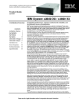
7.5.2
Overview
The Intel® Xeon® Processor 7500 Series-based platform enables memory mirroring
operation by making use of two directly connected socket's Home Agent/
memory_controller as the master mirror agent, and an identical Home Agent/
memory_controller as slave agent. In partial memory configuration, the platform BIOS/
BMC, will configure only one pair of Home Agents in mirror mode, leaving the rest of
Home Agents in non-mirror.
Datasheet Volume 2 of 2
33
Memory Controller (Mbox)
Figure 7-1.
Partial Memory Mirroring (Within a Socket)
Primary
Mirror
Non-Mirrored
Mirrored
MB
MB
MB
MB
MB
Socket A
Mem
Mem
Ctlr 1
Ctlr 2
Non-Mirrored
MB
MB
MB
MB
Mem
Mem
Mem
Mem
Ctlr 1
Ctlr 2
Ctlr 1
Ctlr 2
P rim ary
MB
MB
Socket D
Cores
N o n -M irro re d
N onM irro red
MB
MB
S o c k et A
MB
M em
M em
M em
C tlr 2
C tlr 1
M irro r
MB
MB
C tlr 1
MB
M em
C tlr 1
MB
M em
S o ck e t C
MB
MB
M em
Mem
C tlr 2
C tlr 1
C o re s
Socket B
C tlr 2
N on -M irro re d
N onM irro red
MB
MB
MB
Cores
C ores
34
Ctlr 2
Partial Memory Mirroring (Between Connected Sockets)
M irrored
Note:
Mem
MB
Socket C
Cores
Figure 7-2.
Mem
Ctlr 1
Socket B
Non-Mirrored
MB
MB
MB
MB
Cores
Cores
MB
MB
MB
MB
S o c k et D
M em
C tlr 2
C ores
The overall system configuration will resemble a full memory mirror configuration that
has gone through fail-over operation, where one or more Home Agent mirror pairs will
no longer be operating in mirror mode as the master agent(s) are mapped out/
decommissioned due to failures.
Datasheet Volume 2 of 2
Memory Controller (Mbox)
7.5.2.1
Pre-conditions
• Assumes Master/Slave with identical memory types, and density.
• Assumes existing configuration limitations applicable to full mirror mode of
operation.
7.5.2.2
Sample Scenario
• System manufacturer with tight control on OS kernel will configure the server
platform in partial memory mirroring mode.
• System configuration (SAD entries) is such that the software kernels will be loaded
in physical Home Agent/memory. That hardware is configured to operate in mirror
mode.
• System manufacturer may choose to give option to end user to have the system
configured in mirror mode, partial memory mode, or non-mirror mode.
7.5.2.3
Flow
At cold boot, along with other system initialization, the intended paired Home Agent
master/slave is configured in mirror mode, and mirroring is enabled for that pair.
• Only the Master Home Agent will automatically re-direct all transactions to Slave in
the event of uncorrected errors.
• Non master Home Agent that encounters Uncorrected error will follow non mirrored
flows.
7.6
Mirroring Mode Restrictions
The following mirroring restrictions apply with the listed Tracker Modes:
• Tracker Mode 7 : Only supports intra-socket mirroring
• Tracker Mode 6 : Does not support mirroring
• Tracker Mode 4 : Master and slave should have same rhnid[4:3]
• Tracker Mode 5 : Master and slave should have same rhnid[4]
For details on supported Tracker Modes please refer Table 5-1.
Note:
Tracker Mode 7 does not support Memory Migration.
7.7
Intel® Dynamic Power Technology (Intel® DPT)
The Intel® Dynamic Power Technology allows OS/VMMs to vacate a logical memory
power node and trigger power state transition for the same. Each of the contiguous
ranges of memory that can be power managed is specified as a memory power node in
the ACPI MPST table. A memory power node is a logical memory region describing a
collection of physical memory components (for example, Ranks, DIMMs, Channels) that
can be transitioned in and out of a memory power state at the same time. a memory
power node can also be a portion of a physical memory component. Example: each
rank in a QR DIMM can be individual memory power nodes. memory power nodes are
defined by the contiguous address ranges. Hence if there is are holes in the address
range produced by a physical memory component, multiple memory power nodes are
created. For the Intel Xeon processor 7500 series-based platform, the memory power
node is at a branch (controller, riser) level granularity. Power states supported by
memory components varies across platforms. Each power state can have unique
Datasheet Volume 2 of 2
35
Memory Controller (Mbox)
characteristics like power consumed/saved, entry latency, exit latency. Memory
contents may be retained or lost by a power state. A power state may be controlled by
hardware or software or hybrid. A memory power node can be placed at various power
states depending on the power savings versus latency trade off. the above power state
characteristics are vital for OS/VMM to make this trade off. These numbers are also
provided to OS by BIOS via the ACPI MPST Table.
7.7.1
Memory Power States
Several new memory power states have been added into the EX server segment:
–Dynamic CKE (hardware assisted)
–Memory Standby (software assisted)
–Memory Offline (software assisted)
7.7.1.1
Standby
All the south-bound and north-bound lanes on the Intel SMI are placed in Disable_A
state:
• The clocks driving the Intel 7500 Scalable Memory Buffer Interface are disabled.
• One processor socket memory controller will be in Standby and the other memory
controller will continue to be active. All the DRAM devices behind the Intel 7500
Scalable Memory Buffer are placed in self refresh.
• Intel 7500 Scalable Memory Buffer continues to be powered on and drives DRAM
interface signals to support DIMMs in Self refresh When resuming from Standby to
active state BIOS flow will be used to bring up the link.
• The same exit flow of self refresh will be used to bring DRAMs into active state.
7.7.1.2
Offline
The memory riser can be turned off (offline) and brought back on (online) via MPST
commands, as specified in the ACPI MPST specification.
§
36
Datasheet Volume 2 of 2
Physical Layer (Pbox)
8
Physical Layer (Pbox)
The Intel Xeon Processor E7-8800/4800/2800 Product Families have two fully buffered
DIMM (FBD) ports; each port is of two FBD channels connected to the Buffer-On-Board
(BoB), the Intel 7500 Scalable Memory Buffer. There are four full-width Intel QPI ports
for inter-processor communications. The Physical layer for these internal (FBD) and
external (Intel QPI) channels/links is implemented in Pbox. Pbox implements the digital
logic and analog front end for these interfaces.
8.1
Intel Xeon Processor E7-8800/4800/2800
Product Families Pbox Functional Overview
There are two logic flavors of Pbox, one is FBD-only and the other being Intel QPI-only,
implements the channel/link initialization state machines along with the analog front
end. There are other side band ports which are distributed in four miscellaneous ports
at the sides. Each FBD and Intel QPI port consists of an electrical-block and a digital
sub-block. The electrical sub-block (aka analog front end, AFE) provides the core
analog circuit to enable high-speed differential point-to-point link. The digital sub-block
provides control logic to support AFE.
8.2
Intel® SMI Port specific deltas
1. Transmitter SB Failover Muxing logic extended from 40-bits to 80-bits.
2. Receiver Datapath doubled from 52-bits to 104-bits.
3. Frame Boundary generation logic on Tx and Rx changes with Frame Boundary
counters width.
8.3
Intel® QPI Port specific deltas
Transmitter Nibble Muxing (for Link width modulations) extended from 40-bits to
80-bits.
Datasheet Volume 2 of 2
37
Physical Layer (Pbox)
Mbox
M0
Bbox
B0
Sbox
S0
Sbox
S1
Port-2
Port-6
Port-3
Pbox
PZ0
Intel Xeon Processor E7-8800/4800/2800 Product Families System Interface
Port-1
Pbox
PR0
Port-7
Figure 8-1.
RBox
Port-0
Port-4
Pbox
PR1
Pbox
PR2
Port-5
Bbox
B1
Mbox
M1
Pbox
PZ1
Ubox
UU
Pbox
PR3
Figure 8-1 shows the interface of each of Pbox instances with other uncore boxes. PZ0
and PZ1 are the Pbox-FBD port instances and PR0 to PR3 is the Pbox-Intel QPI port
instances. Not shown here is the PMISC (miscellaneous port) interfaces with uncore.
§
38
Datasheet Volume 2 of 2
Power Management Architecture (Wbox)
9
Power Management
Architecture (Wbox)
The power management control unit, (Wbox), controls power management
functionality based on the current behavior and desired operating point for each of the
cores. Each core provides information on the desired power state of that core, core
temperature information, voltage seen by the core and desired operating frequency to
the Wbox.
The Wbox is responsible for power management functions including:
1. Controlling the voltage regulator for the core voltage
2. Managing transitions between Power States and V/F operating points
3. Detection of and response to thermal events
The voltage supply for the cores is distinct from the voltage supply for the uncore.
There is one voltage regulator for all of the cores, but the voltage supply for each core
is isolated from the main core voltage supply to allow power control to individual cores.
The entire uncore (with the exception of the PLLs) runs at the same voltage, which is
held static, and does not change during operation. The voltage supply for the PLLs is
also static.
9.1
Thermal Management
9.1.1
Thermal Monitoring - 2 (TM2)
When any core's temperature exceeds TM2 threshold, it initiates package wide adaptive
voltage/frequency transition. If the socket remains hot at lowest support V/F (in
response to TM2), it initiates socket wide TM1 to modulate each core clocks to control
temperature. Intel Xeon Processor E7-8800/4800/2800 Product Families
implementation is similar as in Intel Xeon processor 7500 series. Currently, Intel Xeon
Processor E7-8800/4800/2800 Product Families does not include uncore thermal sensor
temp output for any thermal throttling management same as in Intel Xeon processor
7500 series with assumption that uncore will never be hotter then cores when any core
is active.
9.1.2
Thermal Monitoring - 1 (TM1) and T-state
TM1 or T-state is initiated in response to thermal events or OS request through MSR
write (or IO redirection in case of legacy ICH based throttling) resp. Both the events
results in per core clock modulation. Clock modulation duty cycle is fixed for TM1 at
37.5% but is programmable for T-state request at 12.5% granularity. Intel Xeon
Processor E7-8800/4800/2800 Product Families implementation is similar as in Intel
Xeon processor 7500 series.
Datasheet Volume 2 of 2
39
Power Management Architecture (Wbox)
9.1.3
THERMTRIP#
All thermal sensors, including the uncore thermal sensor, have a catastrophic trip
output which is asserted when sensor temperature exceeds its thermtrip threshold
temperature. These signals are all asynchronously or'd together onto the THERMTRIP#
pin. Assertion of any of the catastrophic trip signals causes disabling of all the PLLs
through internal powergood de-assertion for quick response. On recognition of
THERMTRIP#, system takes additional actions to prevent physical damage to various
components on the system including removing power support to the socket. Intel Xeon
Processor E7-8800/4800/2800 Product Families implementation is similar as in Intel
Xeon processor 7500 series.
9.1.4
PROCHOT#
PROCHOT# is asserted on the package when any core thermal sensor's digital value
matches the fused Thermal Monitor trip temperature, it also initiate TM2 transition
internally. Intel Xeon Processor E7-8800/4800/2800 Product Families implementation is
similar as in Intel Xeon processor 7500 series.
9.1.5
FORCEPR#
FORCEPR# is asserted by chipset in response to system hot condition detected in one
of the system component (VR and so forth), processor response to FORCEPR by doing
core V/F transition to lowest support ratio and initiating core clock modulation. Intel
Xeon Processor E7-8800/4800/2800 Product Families implementation is similar as in
Intel Xeon processor 7500 series.
9.1.6
PECI
Intel Xeon Processor E7-8800/4800/2800 Product Families support PECI interface for
platform environment control. PECI implementation is very similar as in Intel Xeon
Processor 7500 Series (with necessary 10 core extension) with support of one
additional feature (Side band P-state control) of limiting P-state through PECI mailbox
command.
9.2
Idle State Power Management
9.2.1
Overview
The power consumption of the processor is an important consideration in the design of
any modern platform. In addition to the power consumed when the processor is active,
there are constraints involving the power consumption when the processor is idle.
In order to minimize the idle power consumption of the processor, multiple low power
idle states are typically implemented. There tends to be an inverse relationship
between the time it takes to enter and exit one of these low power states and the
power consumption while in that state. Idle states with very low power consumption
tend to have longer entry and exit latencies than states with higher power
consumption. The specific low power state to be used is chosen dynamically by the
operating system, based on the usage characteristics of the processor over recent
history.
The interface describing the low power states provided on the processor and how they
are used by the operating system is described via the ACPI (Advanced Configuration
and Power Interface) specification. In ACPI terminology, processor execution states are
40
Datasheet Volume 2 of 2
Power Management Architecture (Wbox)
referred to as ''C'' states. C0 refers to the processor active state, and all other C-states
are idle states. Higher numbered C-states are lower power, but longer latency. C3 is
lower power than C1, and so on.
States C0, C1 require that processor caches maintain coherence – in other words, they
must ensure that any memory requests from other system agents receive the latest
copy of the data if it is stored in the processors cache. The ACPI spec states that cache
coherency in states C3 and lower is the responsibility of the OS to maintain. However,
the entry flow of the Intel Xeon Processor E7-8800/4800/2800 Product Families core
into C3 state includes flushing of the core’s first level and mid-level caches into the
large last level cache. The last level cache remains available, snoopable, and coherent
even if all cores enter C3 state.
ACPI also provides for power management of the system. ACPI S-states refer to the
execution state of the system. S0 is the system active state, and all other S-states are
system idle states. Within the S0 state, a given processor can be active (C0 state) or
idle (C1 or lower states). In all other S-states, the processor is inactive. Note that here
''inactive'' doesn't mean that the processor is any specific C-state – C-states are only
applicable while the system is in S0. As with processor C-states, the latency to enter
and exit an S-state and the power consumed in that state are inversely proportional.
9.2.2
C-State Support
The Intel Xeon processor E7-8800/4800/2800 Product Families will provide support for
C0, C1, C1E, C3, and C6. Note that the behavior in a particular C-state on Intel Xeon
Processor E7-8800/4800/2800 Product Families may be different than states referred
to with the same number on previous products. The platform change, including the
move to an Intel QuickPath Interconnect bus interface, results in the elimination of the
STPCLK#, SLP# signals, and as a result there is no need to support C2 type states on
the Intel Xeon Processor E7-8800/4800/2800 Product Families.
9.2.2.1
Valid C-State Transitions
At an architectural level, a logical processor can only make direct transitions to and
from the C0 state. It cannot transition directly between any other C-states. For
example, a logical processor cannot transition directly from C1 to C3; it must go
through C0.
Valid thread/core C-state transitions are shown in Figure 9-1. Note that the resolved
core C-state is the highest power (lowest numerical) C-state requested by any of the
threads present in that core.
Datasheet Volume 2 of 2
41
Power Management Architecture (Wbox)
Figure 9-1.
Valid Thread/Core Architectural C-State Transitions
C0
MWAIT C1,
HLT
MWAIT ,C6
I/O C6
2
2
2
HALT/
MWAIT
C1E
1
MWAIT C3,
I/O C3
C1E
C1
2
C3
C6
1. No transition to C 0 is needed to service a snoop when in C 1 or C1E.
.
2. Transitions back to C 0 occur on an interrupt or on access
to monitored address
9.2.2.1.1
(if state was entered via MWAIT ).
.
Thread C-States
Each thread in a core can request a transition to a C-state independent of the state of
the other threads in that core. The core will handle coordination of these thread specific
requests; there is no functional need for software to understand the dependencies
between the threads in a core, or the cores in a package, for any given C-state.
9.2.2.1.2
Core C-State Resolution
Any enabled thread in the core is capable of requesting a different C-state. The core
must resolve the C-state requests of each enabled thread, and convey the resolved
request to the Wbox in the uncore on entry to a core C-state. In order to resolve these
requests, the Intel Xeon Processor E7-8800/4800/2800 Product Families must have
access to the current C-state of all threads on the core.
The C-state request is resolved by the core to the lowest numbered C-state requested
by any of the enabled threads on that core. If either thread is in C0, the resolved
C-state is C0. If neither thread is in C0, and 1 thread is in C1, then C1 is the resolved
state, and so on.
Table 9-1.
Core C-State Resolution
If Either Thread Is In
C0
C0
C1, and no threads are in C0
C1
C1E, and no threads are in C0 or C1
42
Then Core Resolved C-State Is
C1E
C3, and no threads are in C0, C1, or C1E
C3
C6 and no threads are in C0, C1, C1E, or C3
C6
Datasheet Volume 2 of 2
Power Management Architecture (Wbox)
9.2.2.2
Package C-State Resolution
The package must resolve the C-state requests of each core in order to determine the
proper package C-state. The C-state request is resolved by the Wbox to the lowest
numbered C-state requested by any of the enabled cores. If any core is in C0, the
resolved package C-state is C0. If no cores are in C0, and at least one core is in C1,
then C1 is the resolved package C-state, and so on. See the following table.
Table 9-2.
Package C-State Resolution
If Any Core Is In
9.2.2.3
Then Package Resolved C-State Is
C0
C0
C1, and no cores are in C0
C1
C3, and no cores are in C0, C1, or C1E
C3
C6 and no threads are in C0, C1, C1E, or C3
C6
Thread/Core C1/C1E Entry
C1/C1E entry can occur on execution of a HLT instruction or execution of an MWAIT
instruction with a C1 (or C1E) argument.
9.2.2.3.1
Thread/Core C1/C1E Exit
A thread in the C1/C1E state will wake up when an interrupt directed to that core
arrives at the local APIC. The APIC will send the wakeup event to the thread if the
event is not masked in the APIC LVT or EFLAGS.IF. When the thread wakes up,
hardware will set the active bit for that core in the Wbox.
9.2.2.3.2
C1E Specific Details
A C1 request will be interpreted as a C1E request in two cases. First, the MWAIT
instruction can be invoked with an argument that specifically requests a C1E transition.
Additionally, IA32_MISC_ENABLES MSR, is used to indicate that all C1 transitions
should be converted to C1E requests.
9.2.2.3.3
Package C1/C1E
If all enabled cores in the package have requested a C1E transition, then the Wbox will
initiate a voltage and frequency change to the minimum operating V/f point. When any
thread exits C1E, the woken thread will begin execution at this minimum operating V/f
point as soon as the event reaches the core.
9.2.2.4
C3
9.2.2.4.1
Thread/Core C3 Entry
C3 entry can occur on execution of an MWAIT instruction with a C3 argument, or via an
I/O read to the P_LVL2 address. The request will result in the execution of a flow, which
will clean up the state of the machine, write the C-state target control register in the
uncore (Wbox) with the core specific request (if this is the last thread to run the C-state
flow), and then put the thread to sleep. If this is the first thread to leave C0 on an SMT
enabled part, the partitioned resources will be re-partitioned on C1/C1E entry. When all
enabled threads are sleeping, core hardware will clear the core active bit in the C-state
target control register in the Wbox.
Datasheet Volume 2 of 2
43
Power Management Architecture (Wbox)
If this is the last enabled thread to enter the C3 or lower state, the Intel Xeon Processor
E7-8800/4800/2800 Product Families flushes the I cache, D cache, and MLC before
putting the thread to sleep. Note that these flush operations are atomic – if a break
event to either thread occurs after the flush of a cache is begun, the flush will
complete.
9.2.2.4.2
Thread/Core C3 Exit
When the core wakes up, the core active bit in the Wbox is set by core hardware. The
core resumes operation at the latest P-state target.
9.2.2.5
Package C3
The package will attempt to enter the package C3 state when all cores have
transitioned to the C3 state or C6 states with at least one core in C3. Once all cores
have entered the C3 state, the Wbox will do system level PMReq negotiation to enter to
Package C3 state and take uncore power saving actions. It sends a PMReq(C3) request
to the platform. If this request is acknowledged with a CmpD(C3) or lower from all Intel
QPI links, the PCU will take further power reduction actions in the uncore. The core
voltage will be reduced to a minimum retention voltage designed to minimize leakage
power while retaining all state values. It will kill the Intel SMI link and do macro clock
gating in some of uncore boxes for power saving.
Once the package has entered the package C3 state, it will be woken when it receives a
core break event. Break events can be forwarded from the system across the Intel®
QuickPath Interconnect bus, or can be the result of internally generated events (probe
mode, thermal threshold interrupts, and so forth).
When a core break event is received, the Wbox will first raise the core voltage to the
minimum active Vcc, re-lock the core PLL(s) to the corresponding frequency and
forward the break event message. If the break event is not masked in the core, the
core will return to the C0 state. If the break event is masked in the core, the Wbox will
re-enter the package C3 state. Package can exit and re-enter sub-states Intel Memory
Self Refresh and macro clock gating for servicing memory access, snoop, and so forth,
while in package C3 state.
9.2.2.6
I/O Support for C-State Requests
Software may make C-state requests by using a legacy method involving I/O reads
from the ACPI-defined processor clock control registers, referred to as P_LVLx. This
feature is designed to provide legacy support for operating systems that initiate C-state
transitions via access to pre-defined ICH registers. On previous products, the base
P_LVLx register is P_LVL2, corresponding to a C2 request. P_LVL3 is C3 and so forth.
Because Intel Xeon Processor 7500 Series has compressed the C-state encoding space,
P_LVL2 corresponds to a C3 request.
Only 'IN' instructions to the supported P_LVLx addresses will trap and redirect to the
MWAIT C-state flow. ''REP INS'', for example, does not redirect. P_LVL2 is defined in
the PMG_IO_CAPTURE MSR. P_LVLx is limited to a subset of C-states. For example,
P_LVL8 is not supported and will not cause an I/O redirection to a C8 request. Instead,
it will fall through like a normal I/O instruction. The range of I/O addresses that may be
converted into C-state requests is also defined in the PMG_IO_CAPTURE MSR, in the 'Cstate Range' field. This field may be written by BIOS to restrict the range of I/O
addresses that are trapped and redirected to MWAIT instructions. Note that when I/O
instructions are used, no MWAIT substates can be defined, and therefore the request
44
Datasheet Volume 2 of 2
Power Management Architecture (Wbox)
defaults to having a sub-state of zero. However, I/O redirected MWAITs always
assumes the 'break on IF=0' control that can be selected using ECX=1 with an MWAIT
instruction.
9.2.2.7
Core C3 Auto Demote
The operating system requests entry to a specific C-state by supplying the appropriate
hint with the MWAIT instruction. If the hint supplied is not supported by the processor,
the thread will request a transition to the next higher power C-state that is supported
by the part. For example, if the OS executed MWAIT with a C9 hint on Intel Xeon
Processor 7500 Series, this would be translated to a C6 request on that specific thread.
Any sub-state requests that originally existed will be kept even if clipping takes effect.
9.3
Core C6 Support
Core C6 is a new power state for the Intel Xeon Processor E7-8800/4800/2800 Product
Families.
9.3.1
Core C6
9.3.1.1
Introduction
As deeper ACPI C-states are reached, leakage power becomes the only remaining
source of power in the processor cores. The ideal low power C-state drives the power of
the core to 0. The goal of the C6 state is to eliminate leakage power by completely
removing voltage from a core or cores.
Before voltage can be removed from a core in C6, it is required to save all processor
state relevant to the processor context in an area which can later be accessed to
restore state and resume operation. This requires a save area which will not be
powered down. On Intel Xeon Processor E7-8800/4800/2800 Product Families a
dedicated C6 SRAM is used to store core state on entry to C6.
9.3.1.2
Thread / Core C6 Entry / Exit
C6 entry can occur on execution of an MWAIT instruction with a C6 argument, or via an
I/O read from the P_LVL3 address.
9.3.2
Core C6 Entry/Exit Flow
A thread enters C6 via one of two mechanisms:
• "MWAIT(C6) • "I/O redirection - An I/O read to an address base and range specified in the
PMG_IO_CAPTURE MSR (0x0E4) is instead redirected to the MWAIT flow.
Core remains in the C6 until it receives break events (interrupts).
9.4
Package C6 Support
Package C6 is a new power state for the Intel Xeon Processor E7-8800/4800/2800
Product Families.
Datasheet Volume 2 of 2
45
Power Management Architecture (Wbox)
9.4.1
Introduction
The PMReq negotiation is done to enter package C6 state where uncore power
optimization actions are taken.The package will attempt to enter the C6 state when all
cores have transitioned to the C6. Once the package has entered the C6 state, it will
only be woken when it receives a break event, memory transaction or a snoop. It also
wake up from macro-clock gating for some of the PECI transactions which requires
uncore clocks. Break events can be forwarded from the system across the Intel QPI
bus, or can be the result of internally generated events. The processor can exit and reenter sub-states, Memory Self Refresh and macro clock gating for servicing memory
access, while in package C6 state.
9.5
Package C3/Package C6 with Memory Self
Refresh
Intel Xeon processor 7500 series-based platform supports the NUMA memory
architecture where access to local memory is much faster than other sockets memory.
The architecture ensures that each socket predominantly access its local memory than
other socket's memory to take benefit of lower access latency. It provides an
opportunity to put Intel SMI port in low power state during package C3 and Package C6
states where all cores in the socket are in deep sleep states leading to significantly low
memory access in these package states. Since local memory can still be accessible by
remove socket at any time (even though infrequently), the uncore needs to detect this
remote memory access and exit from this lower power state to complete transaction
with in acceptable latency. Package C3/C6 with Memory Self Refresh reduces power
across the socket, Intel® 7510/7512 Scalable Memory Buffer, and DIMMs resulting in
overall platform idle power reduction.
9.5.1
Package C3/C6 Memory Self-Refresh Limitations
9.5.1.1
Firmware Interval Timer
If package C3/C6 is enabled then Firmware interval timer counter will be frozen on
package state entry and unfrozen on exit. The duration of freeze tracks package state
residency and is hence traffic pattern dependent.
9.5.1.2
Error Handling
Packet based error signaling is not supported during package C3/C6 if memory self
refresh is enabled.
• Fatal errors: During package C3/C6 the majority of the processor uncore is
powered down therefore only a small subset of fatal errors are allowed.
Recommend relying on pin based signaling ERR#1.
• Recoverable errors: Error can be logged while in package C3/C6, but the
corresponding Intel SMI packet is generated on a wake-up event that brings the
package out of memory self refresh.
• Uncorrectable errors: None possible when processor is in C3/C6 idle power state.
46
Datasheet Volume 2 of 2
Power Management Architecture (Wbox)
9.5.2
PMReq Retry/CmpD Response Behavior
9.5.2.1
PMReq Retry Determination
Retries are the re-querying to other sockets to see if it this node can make transition to
its desired package C-state. Retries are done when it is found that system state is
changed which may cause previous responses from other sockets stale. The retry
request is made in following scenario
• When a node's (socket's) initial PMReq was not granted its desired package C-state
but a higher power C-state. In such case, socket's current package state is not
same as its desired package state. If this socket receives an initial PMRreq from
other nodes (initial request is an indication that some thing has change on system
which might have changed the allowable lowest package C state on the system), it
responds with its CmpD and send its PMReq retry for its own desired package
C-state.
• When a node receives an initial request from other nodes to a higher power C-state
then its own desired package C-state, it needs to retry PMReq for its desire package
C-state fresh co-ordination.
• When a node has sent its PMReq request (initial or retry) and it receives an Initial
PMReq from other node before it can get CmpD response for its request from all
other populated nodes. It indicates that some of the some of the CmpD responses
on the system can be stale. Once the node has received all the CmpD responses, it
has to discard this response due to conflict and retry it's PMReq for fresh coordination.
Even through Ubox implements PMReq conflicts detection in hardware and provides this
information to pcode but as per current implementation pcode ignores this information
and does firmware conflict detection for simplicity and patch ability reasons.
9.5.2.2
CmpD Response Determination
A receiving node has to respond to its inbound PMReq request by a CmpD response
with the data in the response indicating the state_type it is willing other node to hold
currently. In most case, through not all (for desired package C-state < C3 it responds
with C0), a node provides its CmpD response which is same as its current desired
package C-state.
9.5.2.3
PMReq Message Types
The Outgoing PMReqs messages and the Inbound CmpD messages are new features on
Intel Xeon Processor E7-8800/4800/2800 Product Families.
The PMReq interface handles four types of messages:
1. Outbound PMReq messages:
a.
Messages initiated by this node requesting permission from all other nodes for
this node to transition to a "deeper" P/C/S/T state (Intel Xeon Processor E78800/4800/2800 Product Families - will use only for C state), or
b.
Messages initiated by this node to all other nodes announcing a transition of the
node to a "shallower" P/C/S/T state (Intel Xeon Processor E7-8800/4800/2800
Product Families - will use only for C state), or
c.
"Retry" messages initiated by this node in response to a new (not retried) PMReq
message from another node when a previous request by this node was rejected.
2. Outbound CmpD messages:
Datasheet Volume 2 of 2
47
Power Management Architecture (Wbox)
a.
Messages initiated in response to a PMReq message from another node that
indicates the deepest state that this node will permit the originating node to
enter.
3. Inbound PMReq messages:
a.
Requests from other node(s) for permission to transition to a deeper state, or
b.
Announcements from other nodes that they have transitioned to a shallower
state.
4. Inbound CmpD messages:
a.
Responses from other node(s) to a PMReq message from this node.
9.6
S-State Support
9.6.1
Overview
In ACPI terminology, S-states refer to system sleeping states. The Intel Xeon Processor
E7-8800/4800/2800 Product Families support S0, S4 and S15.
Note:
The Intel Xeon Processor E7-8800/4800/2800 Product Families do not support S1
(standalone), S1 with self refresh, and S3 states.
9.7
APIC Timer
The Intel Xeon processor 7500 series when in sleep state C3 and lower, or undergoing
ratio transition, the APIC timer stops running.
For Intel Xeon Processor E7-8800/4800/2800 Product Families the APIC timer is always
running even during sleep state C3 and C6.
9.8
PECI Sideband P-state Control
9.8.1
Overview
Intel Xeon Processor E7-8800/4800/2800 Product Families have added support for
sideband P-state control (limit) through PECI mailbox. Intel Xeon Processor E7-8800/
4800/2800 Product Families have also added support for two new request types P-state
Write and P-State Read in mailbox. Behavior and implementation details for both these
request types are discussed below.
9.8.2
MAILBOX_WRITE_P_STATE_LIMIT (request type = 0x23)
This command (MbxSend with above request type) provides the sideband P-state limit
to the OS requested P-states. The ratio resolution for the OS P-state on package is
done as usual considering various factors voting right and so forth. The sideband Pstate limit is finally applied on top of OS requested resolved P-state (depending on the
package current operating state, it may or may not lead to P-state transition).
Intel Xeon Processor E7-8800/4800/2800 Product Families design supports all clock
ratios between MaxNonTurboRatio (P1) and MaxEfficiencyRatio(Pn) as allowable P-state
request but it may expose only selective clock ratios as valid P-state in ACPI table. Intel
Xeon Processor E7-8800/4800/2800 Product Families supports minimum three OS
requested P-states P0 (assuming turbo is enabled), P1 and Pn.
48
Datasheet Volume 2 of 2
Power Management Architecture (Wbox)
Intel Xeon Processor E7-8800/4800/2800 Product Families expects mailbox sideband
limit request as core clock multiplier ratio corresponding to a valid P-state defined in
ACPI table (ACPI table is visible to PECI Host Controller). The pcode support for
mailbox interface will be designed to accept all possible P-states (clock ratios) limit
requests, it will allow design flexibility to add any new p-state between P1 and Pn. it
expects from PECI host to request only valid P-state same as defined in ACPI table.
9.8.3
MAILBOX_READ_P_STATE_LIMIT (request type = 0x24)
This mailbox command is used by PECI host to readout socket's current sideband Pstate limit. The response data will reflect any clipping applied on this limit internally by
sockets.
§
Datasheet Volume 2 of 2
49
Power Management Architecture (Wbox)
50
Datasheet Volume 2 of 2