1
US007941575B2
(12) United States Patent
(10) Patent N0.:
(45) Date of Patent:
Roy et a1.
(54)
PAUSE REQUEST PROCESSING FOR DATA
TRAFFIC MODIFICATION
(56)
US 7,941,575 B2
May 10, 2011
References Cited
U.S. PATENT DOCUMENTS
(75) Inventors: Andrew Roy, Erie, CO (US); Amit
Bakshi, Sunnyvale, CA (US); Shlomi
7,523,235 B2*
2006/0267798 A1
Nemazie et al. .............. .. 710/74
41/931
710/62
Krepner, Sunnyvale, CA (US); Eugene
2007/0005838 A1*
1/2007 Chang et al.
Fouxman, Mountain View, CA (US);
Dmitry Karpov, San Jose, CA (US);
2007/0189176 A1*
2007/0220357 A1 *
8/2007
9/2007
Douglas Lee, Milpitas, CA (US)
Milne et al. .......... ..
370/241
Vedanabhatla et al. ....... .. 714/43
OTHER PUBLICATIONS
(73) Assignee: LeCroy Corporation, Chestnut Ridge,
NY (US)
Notice:
4/2009
11/2006 Jacobsen et a1.
Subject to any disclaimer, the term of this
patent is extended or adjusted under 35
U.S.C. 154(b) by 653 days.
“SAS Infusion Error Injection Platform for Serial Attached SCSI and
Serial ATA,” LeCroy Protocol Solutions Group, Believed to have
been publicly available as of Dec. 21, 2004, 2 pages.
“SAS Infusion User Manual, Error Injection Platform for Serial
Attached SCSI and Serial ATA,” User Manual Version 1.21 for Soft
ware Version 1.2, LeCroy Protocol Solutions Group, Feb. 2007, 113
pages.
(21) Appl. N0.: 11/681,537
(22)
Filed:
(Continued)
Mar. 2, 2007
(65)
Primary Examiner * Cheng-Yuan Tseng
(74) Attorney, Agent, or Firm * Gordon Kessler
Prior Publication Data
US 2007/0206496 A1
Sep. 6, 2007
(57)
Related US. Application Data
(60)
ABSTRACT
Apparatus and associated systems and methods may relate to
a data tra?ic modi?cation system that may include a process
Provisional application No. 60/779,180, ?led on Mar.
ing module to handle SATA-compliant data transfers in which
3, 2006, provisional application No. 60/779,039, ?led
on Mar. 3, 2006, provisional application No.
a source device or a target device issues requests to pause and
60/779,179, ?led on Mar. 3, 2006, provisional
application No. 60/778,834, ?led on Mar. 3, 2006,
provisional application No. 60/779,084, ?led on Mar.
3, 2006, provisional application No. 60/779,085, ?led
on Mar. 3, 2006, provisional application No.
60/779,264, ?led on Mar. 3, 2006, provisional
application No. 60/892,093, ?led on Feb. 28, 2007.
subsequently to resume the data transfer. In various imple
mentations, a data tra?ic modi?cation device may selectively
modify data tra?ic upon the occurrence of a predetermined
condition. In one illustrative example, if a target device for the
data transfer issues a pause request (e.g., to prevent a buffer
over?ow), the data tra?ic modi?cation device may generate a
pause acknowledge signal to the target device within a
response time speci?ed by the protocol. In another illustrative
example, if a source device for the data transfer issues a pause
(51)
Int. Cl.
(52)
(58)
US. Cl. ............... .. 710/29; 710/33; 710/54; 710/72
G06F 13/38
request, the data tra?ic modi?cation device may generate a
pause acknowledge signal to the source device within the
(2006.01)
response time speci?ed by the protocol.
Field of Classi?cation Search ...................... .. None
28 Claims, 10 Drawing Sheets
See application ?le for complete search history.
1002
Protocol Analyzer
135
{ml 1"}
140
Initiator
Ta at
125
130
Data Traffic
Modi?cation Device
US 7,941,575 B2
Page 2
OTHER PUBLICATIONS
“SAS Infusion, SATA Infusion, FAQ,” LeCroy Protocol Solutions
Group, 2006, 3 pages.
“Finisar Adds SAS and SATA Protocols to Its Industry-Leading
Xgig(R) Analyzer 3.0,” http://investor.?nisar.com/ReleaseDetail.
cfm?pf:yes&ReleaseID:l 86233, printed Feb. 7, 2007, Feb. I, 2006,
2 pages.
“SAS Infusion and SATA Infusion Error Injector and Traf?c Modi
“Finisar Announces Next Generation Analysis Solutions for Storage
?er,” LeCroy Protocol Solutions Group, Believed to have been pub
Area Networks (SANs),” http://investor.?nisar.com/ReleaseDetail.
cfm?pf:yes&ReleaseID:146677, printed Feb. 7, 2007, Oct. 27,
licly available as of Mar. 29, 2005, 6 pages.
“Infusion l.20iRelease Notes,” Updated Aug. 21, 2006, LeCroy
Protocol Solutions Group, Aug. 21, 2006, 5 pages.
“Product Bulletin (#IF-OOl) SAS/SATA Infusion Announcement,”
LeCroy Protocol Solutions Group, Feb. 28, 2005, 2 pages.
“LeCroy Introduces Error Injection System For Serial Attached SC SI
And Serial ATA,” LeCroy Press Release, Mar. 1, 2005, 2 pages.
2004, 2 pages.
“Finisar Announces First Protocol Analyzer for Consumer Electron
ics Storage Interface,” http://investor.?nisar.com/releasedetail.
cfm?ReleaseID:l84656, Jan. 18, 2006, 3 pages.
* cited by examiner
US. Patent
May 10, 2011
Sheet 1 0f 10
1002
US 7,941,575 B2
LL”
Protocol Analyzer
__T
__
J
135
Initiator
140
Target
l_0
125 1
130
Data Traf?c
Modi?cation Device
Iii
FIG. 1
L-5
US. Patent
May 10, 2011
Sheet 2 0f 10
US 7,941,575 B2
200 Z
lnitlatlzr Port
Target Port In
Q2
Q1
tr
Primitive
}
i
j
Input Process
In M Proc 5
p
es
Primitive
Detect
Detect
2
JR
V
m
1L
V
MUX
210
MUX
212
it
v
Event Detect
214
.
DWORD
Event Loggia
Bypass FIFO
FIFO
Sequencers
J
222
j
M
j
Substitute
224
CRC Generate
226
\— Scramble
J! V
V
MUX
21
MUX
2
r
r
tr
Hold Handler
gig
Initiator Port Out
v
Hold Handier
i
i
J!
M
I
3_32
Target Port out
FIG. 2
l
gig
US. Patent
May 10, 2011
Sheet 3 0f 10
US 7,941,575 B2
300 2
SAS Host
‘
*
Data traf?crpodl?catlon
devlce
M
_
:
SAS Device
L0!
15
FIG. 3a
3202
\
SAS Host
-<-—~
110
SAS
<—>
Expander
Datat‘af?c 'Tmdi?cam"
22.5
devlce
<
: SAS Device ‘
\
.125
312
FIG. 3b
330 Z
SAS Host
M
4
>
Data lraf?c ITIOdI?CHlIO?
device
i0!
FIG. 36
SAS
Expander
12;
I
SAS Device I
3L5 J
US. Patent
May 10, 2011
400 Z
Sheet 4 0f 10
US 7,941,575 B2
3. FIFO Under?ow
PR|M_UNDF
A12
1. Both HOLD, or
3. ELSE
2. Local HOLD
2. There was a
CONT in effect
2. No more HOLD. there
is no primitive condition
to re-establish
3. ELSE
PRIM_PR|M4
4
1. Local HOLD
1. Local
HOLD
1. No more HOLD,
must re-establish
1. Local HOLD
2. ELSE
primitive condition
2. There was a CONT
PRIM_SCND
128
in effect, must
re-establish it
FIG. 4
PRIM_CONT
110
US. Patent
May 10, 2011
Sheet 5 0f 10
US 7,941,575 B2
500K
5102
5201
Sent by
530K
5402
Sent by
i
Infusion
Infusion
Sent by
initiator
Target
Sent by
J
Initiator
Port
Port
Target
J
j
1
2
3
4
5
6
Data A
Data B
Data C
Data D
Data E
Data F
R_IP
Data B
CONT
X>0((R__|P)
Data C
Data D
R__|P
t
R__|P
CONT
XXX(R_|P)
)O<><(R_|P)
XXX(R_|P) J
7
a
9
10
Data G
Data H
Data 1
XXX(R_IP}
XXX(R_|P)
HOLD
HOLD
Data E
Data F
Data G
HOLD
HOLD
CONT
Data H
XXX(HOLD)
11 Data K
CONT
~ .~
12 Data L
13 HOLDA
xxxtHOLD)
XXX(HOLD)
14 HOLDA
15 CONT
><xx(HOLD)
XXX(HOLD)
]>o<x(HOLD)
XXX(HOLD)
16 ><>o<(HOLDA)
17 X>O<(HOLDA)
xxxtHoLD)
XXX(HOLD)
xxxtHoLD)
XXX(HOLD)
1s x>o<(HOLDA)
XXX(HOLD)
JXXX(HOLD)
19 XX><(HOLDA)
2o XXX(HOLDA)
21 x><x(HOLDA)
22 XXX(HOLDA)
XXX(HOLD)
X><X(HOLD)
R__|P
R_|P
R_IP
R_1P
CONT
XXX(R_|P)
23 XXX(HOLDA)
CONT
Data J
R_|P
Data A
j
T
T
‘
XXX(HOLD)
f;
XXX(HOLD)
XXX(HOLD)
Data |
x><x(R_|P)
24 )OO<(HOLDA)
XX>(R_|P)
Data J
XXX(R_|P)
25 HOLDA
XXX(R_IP)
Data K
)<>O<(R_IP)
J
XXX(R_|P)
j
26 Data M
>OO<(R_IP)
Data L
27 Data N
28 Data 0
XX><(R_|P)
XXX(R_IP)
ALIGN(0) X>O<(R_|P)
ALIGN(0) XXX(R_|P)
29
Data M
FIG. 5
US. Patent
May 10, 2011
Sheet 6 0f 10
US 7,941,575 B2
6001
610
620
Sent
Infusion
Sent by
Target
Initiator
Port
1 Data A
2
3
4
5
6
R_IP
R_|P
Data B
Data C
HOLD
HOLD
CONT
7 XX><(HOLD
8 XXX(HOLD)
9
OLD)
1O
HOLD)
11
HOLD)
12 HOLD
13 Data D
14 Data E
15 Data F
16 Data G
17 Data H
18
CONT
XXX(R_|P)
IP)
JP)
ta l
)OOQHOLDA
X><X(HOLDA)
)OOQHOLDA
Data E
HOLDA)
HOLDA)
a I
a J
FIG.
JP)
XXX(R_|P)
HOLD
Data D
Data G
Data H
ata L
R P
HOLD)
OLD)
)OOQHOLD)
OLD)
Data F
19 Data J
20
ta K
21
Data A
Data B
Data C
HOLD
HOLD
CONT
OLD
HOLDA
HOLDA
CONT
HOLDA
IP
[P
US. Patent
May 10, 2011
Sheet 7 0f 10
700 Z
US 7,941,575 B2
1&1
V
Receive primitive ‘
from target
7
ause request
primitive?
M
Bypass qaia
NT
Process data
processing
706
“7
V
Send pause
request primitive to
host
Send data to host —
l2
T
Send acknowledge
pause request
_7_1_Q
Buffer data from
7
host
primitive to target
714
718
Receive
acknowledge pause
request primitive
from host?
716
Yes
Receive
in progress
primitive from
target?
720
Yes
Send buffered
data to target
Send receive in
progress primitive
to host
ZLI
FIG. 7
US. Patent
May 10, 2011
Receive primitive
Sheet 8 0f 10
US 7,941,575 B2
‘
from targeé 4 ‘
Is a continue
primitive ?
806
No
1
Save continue
primitive context —>
Buffer data
_L_
Process data
81
A
Send data to host
814
Receive data from
Send buffered
data to target
Is a
continued hold
request?
132
81 8
ti
Send continued
hold request to
target M
Set holding state
822
Recall saved
Yes-> continue primitive
context
828
Re-establish
4: continue primitive
context with host
83
Send acknowledge
N0
*7
pause request
primitive to host
826
FIG. 8
US. Patent
May 10, 2011
<r5m0@<:==2%m01:%0.J
.v/
m’
*wKmO
r
N
m"
w
N
m
Q
.9J03
Sheet 9 0f 10
US 7,941,575 B2
_
f
E0000
_
<1m0@2“_%m<E0N.w_mE2
m uE
umim
O
P
N
W
.V
m
©
N
Q
O
.9Jog$
_<5m0ti1.52%<0m:10,
05.01
Q
028
#wim
O
F
N
m
?
w
N
w
@
om.@_u
US. Patent
May 10, 2011
Sheet 10 0110
US 7,941,575 B2
10002
1010
Glabnl Ruins
f
1000K
(the): In!‘ cc ‘dd l “gauze”
FIG. 10a
lewScenm-lol'l
Sccnnzic Nana: Nnw Banana 1
/
1030
Dir-ensue {ct crm?ic Chlnqblt Ftm 1112:1120:
Global Run.
‘in: tax Any Dunn! {tum llninxacoz!
FIG. 10b
sun {I
(2110i beze La 1321 an evnm»
IOOOZ
FIG. 10c
Scmnme Run-n:
Dxraczurn 20! I!!!
» flan inlzincor
h: Mid all want)
Ci: ixrmr ilzou Xmnnon
ENC Duty-2t * Sand Henmvn min
1070
' FIG. 10d
1030
US 7,941,575 B2
1
2
PAUSE REQUEST PROCESSING FOR DATA
TRAFFIC MODIFICATION
tem interface)), and SATA Tunneling Protocol (STP). Com
munication errors can occur when data transfers do not meet
the protocol speci?cations.
CROSS-REFERENCE TO RELATED
APPLICATIONS
SUMMARY
Apparatus and associated systems and methods may relate
This application claims priority to: US. Patent Application
Ser. No. 60/ 779,039, entitled “Data Capture Method And
Apparatus,” which was ?led by Roy, A., et al. on Mar. 3, 2006;
US. Patent Application Ser. No. 60/779,l79, entitled “Pro
tocol Traf?c Modi?cation Method And Apparatus,” which
to a data traf?c modi?cation system that may include a pro
cessing module to handle SATA-compliant data transfers in
which a source device or a target device issues requests to
et al. on Mar. 3, 2006; US. Patent Application Ser. No.
pause and subsequently to resume the data transfer. In various
implementations, a data tra?ic modi?cation device may
selectively modify data tra?ic upon the occurrence of a pre
determined condition. In one illustrative example, if a target
device for the data transfer issues a pause request (e.g., to
prevent a buffer over?ow), the data tra?ic modi?cation device
60/779,084, entitled “Scenario View Method And Appara
tus,” which was ?led by Lee, D., et al. on Mar. 3, 2006; US.
may generate a pause acknowledge signal to the target device
within a response time speci?ed by the protocol. In another
Patent Application Ser. No. 60/779, 180, entitled “Processing
illustrative example, if a source device for the data transfer
issues a pause request, the data tra?ic modi?cation device
may generate a pause acknowledge signal to the source
was ?led by Fouxman, E., et al. on Mar. 3, 2006; US. Patent
Application Ser. No. 60/ 778,834, entitled “Cross Platform
Trigger MethodAnd Apparatus,” which was ?led by Roy, A.,
Of Hold Command In Protocol Analyzer,” which was ?led by
Roy, A., et al. on Mar. 3, 2006; US. Patent Application Ser.
20
device within the response time speci?ed by the protocol.
No. 60/779,085, entitled “Communication Flow Recovery
Certain embodiments may provide one or more advan
Method and Apparatus,” which was ?led by Karpov, D. on
tages. For example, a data traf?c modi?cation system may
Mar. 3, 2006; and, US. provisional patent application 60/ 779,
264 entitled, “Impairment and Monitoring Apparatus and
Method,” by Roy, A., et al., which was ?led Mar. 3, 2006. This
application also claims priority to US. Patent Application
smoothly and robustly handle high speed data transfers
25
Ser. No. 60/ 892,093, entitled “Data Tra?ic Modi?er Method
and Apparatus,” which was ?led by Roy, A., et al. on Feb. 28,
2007. The disclosures of each of these priority documents are
incorporated herein by reference.
between a wide variety of source and target devices. In vari
ous implementations, the data tra?ic modi?cation device may
overcome the delay associated with buffering the data trans
fer by monitoring bidirectional data tra?ic for pause requests,
and responding rapidly by generating expected acknowledge
30
signals within the response time expected by the device that
issued the pause request. In some particular embodiments, a
device capable of in-line data traf?c modi?cation device may
respond to pause request signals within a response time (e. g.,
TECHNICAL FIELD
20 double words) as speci?ed by various protocols (e.g., SAS,
Various embodiments relate to apparatus for modifying
data traf?c signals.
35
BACKGROUND
source device, a data tra?ic modi?cation device may advan
tageously restore a context in effect when the data transfer
Data rates continue to increase in digital systems, commu
nication systems, computer systems, and in other applica
40
tions. In such applications, various devices communicate data
using signals that may be encoded with information in the
form of signal levels (e.g., amplitude) in certain intervals of
45
The details of one or more embodiments are set forth in the
accompanying drawings and the description below. Other
features, objects, and advantages will be apparent from the
description and drawings, and from the claims.
tend to decrease.
Likewise, operating frequencies for some analog signal
processing systems continue to increase along with advances
in telecommunication technologies, for example.
was paused. In another example, after generating an acknowl
edge signal in response to a pause request from a target
device, the data tra?ic modi?cation device may advanta
geously buffer data from the source device until the pause
request propagates to the source device, and the source device
pauses the data transfer in response to the pause request.
time. Proper decoding of signals, for example, may involve
measuring small signal levels in the correct time intervals. As
data rates increase, margins of error for the signal level timing
STP, SATA, SATA 2.0, and the like). In one example, before
resuming a data transfer after being paused by, for example, a
50
DESCRIPTION OF DRAWINGS
Various test and measurement equipment may be used to
verify signal integrity in analog and digital systems. For
FIG. 1 illustrates a block diagram of an exemplary con?gu
ration capable of modifying data traf?c.
example, oscilloscopes may be used to measure analog wave
forms, and protocol analyzers may be used to monitor data in
digitally formatted signals. Other waveform processing
55
equipment may provide signal processing operations that
may include, but are not limited to, acquisition (e.g., sam
pling, monitoring) and/or modi?cation (e.g., ?ltering, time
shifting, ampli?cation) of analog and/or digital signal wave
forms.
60
FIG. 2 is a block diagram of an exemplary data traf?c
modi?cation device.
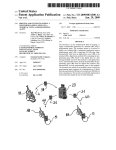
FIGS. 3a-c are block diagrams depicting exemplary con
?gurations for using a data tra?ic modi?cation device.
FIG. 4 is a ?ow diagram of an exemplary state machine for
data tra?ic modi?cation.
FIG. 5 is a table that illustrates an exemplary communica
In a typical data transfer, a data source device may transmit
data to be received by a target device. Data transfers may be
tion session among a SATA initiator, a data traf?c modi?ca
performed according to electrical and timing parameters
speci?ed by a communication protocol. Representative
examples of well-known serial communication protocols
include Fibre Channel, SATA (Serial Advanced Technology
Attachment), SAS (serial attached SCSI (small computer sys
requests a hold.
FIG. 6 is a table that that illustrates an exemplary commu
nication session among a SATA initiator, a data traf?c modi
tion device, and a SATA target, when the SATA target
65
?cation device, and a SATA target, when the SATA initiator
requests a hold.
US 7,941,575 B2
3
4
FIG. 7 is a block diagram depicting an exemplary method
for processing a pause request from a SATA target coupled to
FIG. 2 is a block diagram 200 depicting an exemplary data
How through the data tra?ic modi?cation device 105 of FIG.
1. Communications data may enter the data tra?ic modi?ca
tion device 105 through an initiator port in 202, or through a
a data traf?c modi?cation device.
FIG. 8 is a block diagram depicting an exemplary process
for handling a context using in a data tra?ic modi?cation
device.
FIGS. 9a-c illustrate tWo exemplary data substitution pro
cesses being performed upon the data stream.
FIGS. 10a-d illustrate an exemplary graphical user inter
target port in 204. Data entering though the initiator port in
202 then passes to a ?rst primitive detect module 206 and a
?rst input processing module 208. In some embodiments, the
primitive detect module 206 may be con?gured to react to (or
“snoop for”) selected SATA primitives such as “HOLD.”
face for vieWing and editing data modi?cation scenarios.
Data entering the block diagram 200 through the target port in
204 passes through a second input processing module 207
DETAILED DESCRIPTION
and a second primitive detect module 209.
Data passing through the input processing module 208 is
FIG. 1 illustrates a block diagram 100 of an exemplary
con?guration for using a data traf?c modi?cation device 105.
The data traf?c modi?cation device 105 may be used to
selectively modify some or all data tra?ic ?oWing betWeen a
then passed to a ?rst multiplexer 210, a second multiplexer
212, and an event detection module 214. The ?rst multiplexer
210 and second multiplexer 212 (as Well as a third multiplexer
216 and a fourth multiplexer 218) are present to control the
paths through Which each direction of data tra?ic should
SATA (Serial Advanced Technology Attachment) initiator
110, such as a computer With a SATA interface, and a SATA
target 115, such as a hard disk drive or drive array. In some
20
propagate through the block diagram 200. In the depicted
25
example, both directions of data tra?ic are monitored, but
only one direction of data traf?c can be selectively modi?ed
at any one time. The direction of data traf?c to be selectively
modi?ed is routed by the multiplexers to a dWord FIFO 236,
While the opposite direction of data tra?ic is routed through a
embodiments, the selective modi?cation of data may be per
formed on data tra?ic in one or more directions. In some
embodiments, the data may be modi?ed to purposely alter the
communications betWeen the SATA initiator 110 and the
SATA target 115.
In the depicted example, the con?guration 100 includes the
data tra?ic modi?cation device 105, the initiator 110, the
target 115, and a protocol analyZer 120. The data tra?ic modi
bypass FIFO 234.
In some other embodiments, more than one direction, lane
or channel of data traf?c may be modi?ed at any one time. For
?cation device includes a ?rst port 125 and a second port 130.
In this example, the ports 125, 130 are compliant With the
SATA standard, and include tWo pairs of conductors in order
to alloW for bidirectional communications. The ?rst port 125
30
described beloW With reference to FIG. 2, may be added to
permit selective modi?cation of data traf?c in both directions
of a bidirectional communication link, for example.
In FIG. 2, data passing through the second multiplexer 212
is in communication With a ?rst channel 135 of the protocol
analyZer 120, and the second port 130 is in communication
With a second channel 140 of the protocol analyZer 120. The
?rst port 135 is also in communication With the initiator 10,
and the second port 140 is also in communication With the
target 115.
In the con?guration 100, communications betWeen the
SATA initiator 110 and the SATA target 115 may be modi?ed
by the data traf?c modi?cation device 105 and traced by the
protocol analyZer 120. This con?guration may alloW a tech
nician to con?rm that the data traf?c modi?cation device 105
has been con?gured correctly, or may alloW a technician to
observe hoW the SATA initiator 110 or SATA target 115
example, multiplexers may be removed and/or additional
hardWare and corresponding softWare, examples of Which are
35
40
?oWs through the dWord buffer 236. In some embodiments,
the dWord buffer 236 may be monitored by an event detect
module 214, an event logic module 220, and/or a sequencer
module 22', Which couples to a substitution module 224.
Data from either or both of the input process modules 207,
208 may be received as inputs to the event detection module
214, Which may be con?gured (e.g., programmed) to identify
selected primitives, out-of-band (OOB) messages, and the
like. The event detection module 214 may be con?gured, for
example, to identify user-Speci?ed input conditions, the
45
respond When either receives modi?ed data.
While the exemplary con?guration 100 has been described
occurrence of Which may cause a processor to perform opera
tions to selectively modify the data stream, for example.
than SATA. In some examples, the con?guration 100 may use
a SATA-compliant protocol such as SAS (serial attached
Signals from the event detection module 214 are received by
the event logic module 220, Which can be programmed by the
user to provide a speci?ed response to certain speci?ed trig
ger conditions (e.g., primitives and data patterns detected in
the event logic module 220). These responses may include
actions that selectively modify data in the data stream, drop
SCSI (small computer system interface)) and/or SATA Tun
neling Protocol (STP). In some embodiments, the data tra?ic
form a combination of these or other actions.
in terms of communications according to a version of SATA
standard, various embodiments may use various versions of
the SATA protocol (e.g., SATA 2.0), and/or protocols other
modi?cation device 105 may also be capable of using a com
50
data, sound an audible beep, stimulate a trigger port, or per
55
From the event logic module 220, control passes to a
sequencer module 222. The sequencer module 222 may be
implemented as a user-programmable state machine. The
sequencer module 222 state machine may be con?gured to
60
add to, ignore, remove, and/or replace some or all of the bits
in a frame of data) the data stream. The data is then sent to a
substitution module 224. The substitution module 224 may
cooperate With the sequencer module 222 to selectively
modify one or more bits Within a data frame, for example,
based on operation of the state machine. Such substitutions
may be performed, for example, in order to inject an error to
test the response of the initiator 110 and/or the target 115.
bination of protocols. For example, the con?guration 100
may be implemented With the SAS initiator 10 using SAS and
the target 115 using SAS, STP, or SATA. In some further
examples, a hub may be included to provide connections
betWeen at least one initiator 110 and at least one target 15,
Where each connection may use a combination of protocols.
cooperate With the event logic module 220 to modify (e.g.,
Further aspects and examples relating to data traf?c modi?
cation are described in US. provisional patent application
60/779,264 entitled, “Impairment and Monitoring Apparatus
and Method,” by Roy, A., et al., Which Was ?led Mar. 3, 2006,
and the contents of Which are incorporated herein by refer
ence.
65
US 7,941,575 B2
6
5
In some implementations, the data traf?c may have data
tive detect module 209 is con?gured to detect and react to
frames that include CRC (cyclical redundancy check) data,
pause requests from the target. In operation, the primitive
which may be used to verify the integrity of the data that is
received. When the substitution module 224 modi?es data in
the data frame, the CRC for that frame may be incorrect for
the modi?ed data frame. A CRC generation module 226 may,
for example, recalculate valid CRC data for the frame, and
substitute this recalculated CRC data for the original CRC
data in the data frame. Examples of processes for data sub
detect module 209 may react by signaling the hold handler
238 to generate a pause request acknowledge signal back to
the target. This process may allow a pause acknowledgement
signal to be sent to the target while avoiding the delay asso
ciated with propagating through the buffer FIFOs 234, 23 6. In
this example, data being transferred from the initiator may
continue to be sent until the initiator receives and responds to
stitution in a data tra?ic modi?cation device are described in
the pause request after the pause request propagates through
one of the FIFOs 234, 236. During this time, the valid data
further detail in Us. provisional patent application 60/779,
039 entitled, “Data Capture Method and Apparatus,” by Roy,
sent by the initiator may be buffered in one of the FIFOs 234,
236 at least until the target breaks the pause state and the data
A., et al., which was ?led Mar. 3, 2006, and the contents of
which are incorporated herein by reference. Control then
transfer resumes.
In another illustrative example, an initiator (e.g., host
device) may issue a pause request. After the pause request is
issued, some time may pass while the pause request propa
passes to a scrambler module 228. The scrambler module 228
may reduce the transmission of long repetitive data patterns
that could contribute to electromagnetic interference.
Data leaving the scrambler module 228 is then passed to
the third multiplexer 21 6 and the fourth multiplexer 218. Data
passed to the third multiplexer 216 may pass the data to the
fourth multiplexer 218, or vice versa, or the data may be
passed to a ?rst hold handler 230 or a second hold handler
238. Data passed to the ?rst hold handler 230 is sent to the
initiator via an initiator port out 232. Data passed to the
second hold handler 238 is sent to the target via a target port
gates though the block diagram 200 (e.g., from the initiator
port in 202, to the ?rst input processing module 208, through
20
such, the target may acknowledge the pause request after
some delay that, in some examples, may exceed the response
time speci?cation for the communication protocol. After the
initiator issues the pause request, the ?rst primitive detect
25
out 240.
In operation, the exemplary block diagram 200 illustrates a
data tra?ic modi?cation device con?gured to substantially
reduce the propagation times that add delay to the acknowl
edgment of a pause request from either an initiator or a target
one ofthe FIFOs 234, 236, and to the target port out 240). As
30
device. Data propagating through the data modi?cation path
module 206 may detect the pause request and pass control to
the ?rst hold handler module 230. The ?rst hold handler
module 230 then generates a pause acknowledgement mes
sage that is sent out the initiator port out 232. When the
initiator breaks the pause state, the substitution module 224
may generate signals to restore the context of the data stream
that was in effect when the pause request was received.
(modules 214, 220-228, 236) may experience a delay caused
Examples of restoring the context upon resuming the data
by the previously described processing steps. Some commu
transfer are described in further detail with reference to FIG.
4.
nication protocols, such as the SATA speci?cation, for
example, specify that a transmitting device must, within a
speci?ed response time such as 20 dwords (double words, or
32-bit values), acknowledge a pause request signal by sus
pending the transmission of valid data and by sending a hold
35
request may include a SATA HOLDA primitive, and the
continue primitive may include a SATA CONT primitive.
acknowledgement signal to acknowledge the pause request.
The pause request may be to prompt the initiator to suspend
the data transfer to avoid, for example, a buffer over?ow,
40
which may result in a loss of data or other problems. The data
paths for propagating the pause request through the data
Some protocols may specify certain rules associated with
such primitives. For example, some protocols may impose a
response speci?cation that a pause request, for example, be
acknowledged within a certain time period or that only a
limited quantity of data in the data stream be transferred after
tra?ic modi?cation device (e. g., from the target port in 204 to
the initiator port out 232) include a buffer or memory. In the
In some embodiments, such as those that use a version of
the SATA protocol, the pause request may include, for
example, a SATA HOLD primitive, the acknowledge pause
45
a pause request is issued. Examples of processing pause
depicted example, and depending on the states of the multi
primitives in a data tra?ic modi?cation device are described
plexers 210, 212, the data path through which a pause request
in further detail in Us. provisional patent application 60/ 779,
180 entitled, “Processing Of Hold Command In Protocol
Analyzer,” by Roy, A., et al., which was ?led Mar. 3, 2006,
would propagate includes either the bypass FIFO 234 or the
dword FIFO 236. The FIFOs 234, 236 may be, for example,
buffers FIFO (?rst in-?rst out), FILO (?rst in-last out), circu
50
lar, linear, parallel, or combinations of these or other types of
buffers. In some embodiments, the FIFOs 234, 236 may be
implemented using pointers to memory locations, one or
In some implementations, the tra?ic modi?cation device
105 may generate pause request acknowledgement signals to
more data stores, shift registers, or a combination of these or
other buffering techniques.
55
In operation of the example block diagram 200, the data
to FIGS. 4-8.
FIGS. 3a-c illustrate exemplary block diagrams depicting
60
for the protocol being used. Various embodiments may be
adapted to meet a protocol’s response time speci?cation.
In an illustrative example, a target device (e. g., disk drive)
various con?gurations for using a data tra?ic modi?cation
device. FIG. 3a illustrates an exemplary block diagram 300 of
an embodiment for the use of a data tra?ic modi?cation
device 305. In this embodiment, the data tra?ic modi?cation
device 305 is placed between a SAS host 310 and a SAS
device 315. In some embodiments, the SAS device 315 may
may issue a pause request to an initiator (e. g., host or server)
that is transferring data to the target device. The target may
issue a pause request, for example, if it is receiving data faster
that it can process the data. In the depicted ?gure, the primi
satisfy the response time speci?ed by the applicable proto
cols. Exemplary implementations for processing pause
requests in the con?guration 100 are described with reference
tra?ic modi?cation device may introduce a delay in the data
stream. In some examples, such delay may substantially pre
vent the device requesting a pause from receiving a pause
acknowledgment signal within response time speci?cation
and the contents of which are incorporated herein by refer
ence.
65
be replaced by a SATA device. In some embodiments, the
SAS host 310 may be a SATA host if the con?guration also
includes a SATA device.
US 7,941,575 B2
8
7
FIG. 3b illustrates and exemplary block diagram 320 of
Was in place prior to the arrival of the continued pause request
from the host. Once the prior target context is reestablished,
the state machine 400 transitions back to the PRIM_IDLE
another embodiment for the use of the data traf?c modi?ca
tion device 305. In this embodiment, the SATA host 310 is
connected to a SAS expander 325. The SAS expander 325 is
also connected to the data tra?ic modi?cation device 305, and
the data tra?ic modi?cation device 305 is connected to the
SAS device 315.
FIG. 30 illustrates an exemplary block diagram 330 of
another implementation of the data tra?ic modi?cation
device 305. In this example, the SAS host 310 is connected to
the data tra?ic modi?cation device 305, the data tra?ic modi
?cation device 305 is connected to the SAS expander 325, and
the SAS expander 325 is connected to the SAS device 315.
FIG. 4 illustrates a How diagram of an exemplary state
state 402.
In another example, the SATA host may send a pause
request after sending data to the target (as Will be further
illustrated by FIG. 6 and FIG. 8). In this case, the state
machine 400 starts in the PRIM_IDLE state 402 Where the
data traf?c modi?cation device propagates data betWeen the
host and target. During this state, the target sends a continued
receiving message (e.g., a “R_IP-R_IP-CONT” sequence)
machine 400 used in a data traf?c modi?er. In one example, a
SATA host may be sending data to a SATA target When the
SATA target sends a pause request (as Will be further
described With reference to FIG. 5 and FIG. 7). The state
machine 400 starts in a PRIM_IDLE state 402. During this
state, the data traf?c modi?cation device propagates data
20
betWeen the host and the target. In the depicted example, the
host is sending data to the target. If the data traf?c modi?ca
tion device detects that the target has sent a pause request
(e.g., a “HOLD” primitive), the state machine 400 responds
by propagating the pause request to the host and transitioning
PRIM_SCND state 408. During the PRIM_SCND state, the
data tra?ic modi?cation device recalls the previously stored
25
to a PRIM_PRIM state 404. During the PRIM_PRIM state
404, the data tra?ic modi?cation device generates a series of
hold acknowledgements (e.g., a series of “HOLDA” primi
tives) and sends them to the target, and buffers any data that
the host sends until the host acknowledges the pause request.
When the target is once again able to receive data, the target
may send a receiving message (e.g., a “R_IP” primitive, or a
R_IP-R_IP-CONT sequence). When the data tra?ic modi?
cation device senses such a receiving message, and there is no
continued state to re-establish, the state machine 400 propa
gates the receiving message to the host and transitions to a
30
35
FIG. 5 illustrates a table 500 that that depicts an exemplary
communications session among a SATA initiator (shoWn in
column 510), a data traf?c modi?cation device, a data traf?c
modi?cation device’s initiator port (shoWn in a column 520),
45
R_IP-CONT” sequence) from the target. The data tra?ic
50
initiator is sending data in cycles 1-3. It can also be seen that
the target is sending a R_IP-R_IP-CONT sequence in cycles
1-3 to indicate that the target is receiving data. At cycles 3-5,
it can be seen that the R_IP sequence sent by the target has
been relayed to the initiator port after some delay. LikeWise,
55
and to resume propagating the data stream. In some embodi
ments, the SATA primitives that may be used to break a
continued state may include, but are not limited to, HOLD,
a data tra?ic modi?cation device’s target port (shoWn in a
column 530), and a SATA target (shoWn in a column 540). It
should be noted that this table does not represent any particu
lar time scale, and is intended to be only a general depiction of
one possible How of communications. In this example, the
request from the host (e.g., a “HOLD-HOLD-CONT”
state machine 400 propagates the continued pause request to
the target, stores the context of the continued primitive mes
sage from the target, and then transitions to the PRIM_PRIM
state. While in the PRIM_PRIM state, the data traf?c modi
?cation device generates a series of hold acknoWledgement
messages and sends them to the ho st. The ho st may then send
a single pause request to break the continued pause request
istic of the previous target context. The state machine 400
then transitions to the PRIM_EXIT state 406 to send any
buffered data that may be in the data tra?ic modi?cation
device, and then returns to the PRIM_IDLE state 402.
In some embodiments, the series of hold acknoWledgement
statements sent during the PRIM_PRIM state may be
40 XXX(HOLDA) . . . sequence).
modi?cation device may also receive a continued pause
sequence). Upon detection of the continued pause request, the
the data traf?c modi?cation device sends a continuation
request to the target to reestablish the “continued” character
replaced by a continued hold acknoWledgement message
sequence, folloWed by a series of scrambled “keep alive”
messages (e.g., a HOLDA-HOLDA-CONT-XXX(HOLDA)
request after sending one or more primitives. In this case the
state machine 400 starts in the PRIM_IDLE state 402. During
the PRIM_IDLE state the data traf?c modi?cation device
may receive a continued primitive message (e.g., a “R_IP
target context information, and uses that information to rees
tablish the previous context. Since the previous context Was a
continued command, the state machine 400 transitions to a
PRIM_CONT state 410. During the PRIM_CONT state 410,
PRIM_EXIT state 406. During the PRIM_EXIT state 406,
the data tra?ic modi?cation device sends any data that may
have been buffered. When the buffer has been emptied, the
state machine 400 transitions back to the PRIM_IDLE state
402.
In another example, the SATA host may send a pause
and the host sends data. If the data tra?ic modi?cation device
detects that the host has sent a continued pause request, the
data tra?ic modi?cation device propagates that continued
pause request to the target, stores the current context infor
mation, and transitions to the PRIM_PRIM state 404. During
the PRIM_PRIM state 404, the data traf?c modi?cation
device generates and sends a series of hold acknoWledgement
messages to the host. If the data tra?ic modi?cation device
then detects that the host has sent a command primitive to
break the continued pause request, the state machine 400
propagates the primitive to the target, and transitions to the
60
HOLDA, PMREQP, PMREQS, RERR, R_IP, R_OK,
at cycle 7 the target sends a pause request as part of a HOLD
HOLD-CONT sequence, and after a similar delay the HOLD
HOLD-CONT sequence is relayed at the initiator port. Due to
the normal delay required for the initiator to respond to a
pause request, in addition to the delay introduced by the data
traf?c modi?cation device, the initiator does not respond to
the pause request until cycle 13, When it sends a hold
R_RDY, SYNC, WTRM, or XRDY. The state machine 400
acknoWledgement primitive. In some instances, this delayed
responds by propagating the message to the target and tran
sitioning to a PRIM_SCND state 408. During the PRIM_
response may cause a buffer overrun if all the data packets
SCND state 408, the data traf?c modi?cation device recalls
the stored context information and uses that stored context
information to reestablish the continued target context that
65
Were sent directly to the target. In order to prevent a possible
buffer overrun, the data traf?c modi?cation device generates
a series of hold acknoWledgement primitives (starting at cycle
11 as depicted by the shaded cells) and transmits them to the
US 7,941,575 B2
10
target. During cycles 9-12 the initiator continues to send data
primitives. The tra?ic modi?cation device buffers these
primitives until the target device breaks the continued HOLD
at cycles 19-21. At cycles 21-23 the tra?ic modi?cation
then control passes to step 718. If at step 720 a read in
progress primitive is received from the target, then the process
continues at step 722. During step 722, data buffered in the
FIFO (if any) during step 714 is sent to the target. At step 724,
device breaks the continued HOLD it has established With the
initiator, and at cycle 23 the data tra?ic modi?cation device
begins to empty its FIFO by transmitting buffered data to the
target. At cycle 27, the FIFO has been emptied and the data
tra?ic modi?cation device sends a pair of ALIGN(0) primi
tives, for example, to keep the data line active until the “Data
M” primitive sent by the initiator in cycle 26 can be sent to the
a read in progress primitive is sent to the host. In some
embodiments, this may signal the host that the target or the
data tra?ic modi?cation device is ready to accept data.
FIG. 8 is a block diagram ofan exemplary process 800 for
re-establishing a context in a data tra?ic modi?cation device.
The process begins at step 802, Which could be entered auto
matically upon poWer-up, in response to a softWare request, in
response to an electrical signal, or other methods for initiating
target in cycle 29.
FIG. 6 illustrates a table 600 that depicts an exemplary
communications session among a SATA initiator (shoWn in a
column 610), a data traf?c modi?cation device’ s initiator port
(shoWn in a column 620), a data traf?c modi?cation device’s
target port (shoWn in a column 630), and a SATA target
(shoWn in a column 640). It should be noted that this table
does not represent any particular time scale, and is intended to
be only a general depiction of one possible How of commu
a softWare process in a data tra?ic modi?cation device or
combinations thereof. At step 804 a primitive is received from
a target. If, at step 806, the primitive is determined to be a
continue request primitive, then control passes to step 808. At
step 808, the data tra?ic modi?cation device saves the context
of the continue request primitive. For example, the continue
20
nications. In this example, the initiator is sending data during
request primitive may be part of a continued read in progress
primitive combination of messages. In this case, the data
cycles 1-3, and then sends a HOLD-HOLD-CONT sequence
traf?c modi?cation device Would save information that Would
alloW the data tra?ic modi?cation device to recall the contin
during cycles 4-6. The data tra?ic modi?cation device
responds by storing the current context that it is in (a contin
ued R_IP), relaying the HOLD sequence to the target device
during cycles 6-8 and by generating a series of HOLDA
frames (depicted by shaded cells) as an acknoWledgement to
the initiator starting at cycle 8.At cycle 12, the initiator breaks
the continued HOLD by sending a single HOLD primitive,
ued read in progress primitive state. After this information is
saved, control passes to step 810.
If, at step 806, the primitive received from the target is not
a continue request primitive, then control passes to step 810.
At step 810, the data tra?ic modi?cation device begins to
buffer data from the target in a FIFO. At step 812, the data
traf?c modi?cation device may process of otherWise modify
after Which the initiator resumes transmission of data frames
25
30
during cycle 13. The data tra?ic modi?cation device responds
by reestablishing the previously saved context by recalling
that it Was in a continued R_IP state and transmitting a R_IP
R_IP-CONT sequence to the initiator during cycles 17-19.
FIG. 7 illustrates an exemplary block diagram depicting a
35
process 700 for handling a pause request from a SATA target
in a data tra?ic modi?cation device, for example, the process
illustrated by FIG. 5. The process begins at step 701, Which
40
primitive is received from a target. If, at step 704, the primi
tive received at step 702 is not a pause request, then control
passes to step 708.
at step 824, the data tra?ic modi?cation device is not in a
45
otherWise modi?ed in a manner, for example, such as that
described by blocks 212-214, 220-228, and 236 ofFIG. 2. At
50
target.
If, at step 704, the primitive received at step 702 is a pause
request primitive, then the process continues at step 706. At
step 706, the pause request primitive is alloWed to bypass data
55
processing steps. At step 712 the unprocessed pause request
host in a FIFO.
60
received from the host, then control passes to step 720. If, at
step 716, an acknoWledge pause request primitive is not
received from the host, then control passes to step 718. Dur
traf?c modi?cation device sends a acknoWledge pause
request primitive to the initiator. The process then continues
at step 832, Where any data that may have been buffered from
the target is sent to the host.
At step 828, the data tra?ic modi?cation device recalls the
state that Was saved during step 808 and uses that state infor
mation to re-establish the continued state at step 830. For
example, if the saved state Was a continued read in progress
primitive state, the data tra?ic modi?cation device may send
the target.
FIGS. 9a-c illustrate a stream of data, and tWo exemplary
data substitution processes being performed upon the data
stream. FIG. 9a depicts a series often dWords in a section of
a data buffer 900, Where each dWord is numbered 0-9. In these
ing step 718, the acknoWledge pause request primitive is sent
to the target.
If, at step 720, the data tra?ic modi?cation device does not
receive a read in progress primitive from the target device,
holding state, then the process continues at step 826, other
Wise the process continues at step 828. At step 826, the data
a continued read in progress primitive sequence to the host.
Control then passes to step 832 Where any data that may have
been buffered from the target is sent to the host. The process
then returns to step 804 to receive additional primitives from
primitive is sent to the host. At step 714, the data tra?ic
modi?cation device begins to buffer data received from the
If, at step 716, a acknoWledge pause request primitive is
so the data traf?c modi?cation device can recall that the
device is in this state. Control then passes to step 824.
If, at step 818, the incoming data is not a continued pause
request primitive sequence, then control passes to step 824. If,
At step 708 data is processed. For example, this may mean
that the data received from the target may be processed or
step 710, processed data is sent to a host. Control then passes
back to step 702, to receive additional primitives from the
sequence, then control passes to step 820. At step 820, the
continued pause request primitive sequence is sent to the
target. At step 822 the data tra?ic modi?cation device sets a
holding state. In some embodiments, this may involve saving
data, setting a register bit, or other types of computer memory,
could be entered automatically upon poWer-up, in response to
a software request, in response to an electrical signal, or other
methods for initiating a softWare process in a data tra?ic
modi?cation device or combinations thereof. At step 702, a
data from the host in a manner possibly such as that described
by blocks 212-214, 220-228, and 236 of FIG. 2. At step 814,
the processed data is sent to the host.
At step 816, data is received from the host. If, at step 818,
the incoming data is a continued pause request primitive
65
examples, the dWord 0 arrived in the buffer ?rst, and each of
the dWords arrived in sequence until dWord 9 Which arrived
last. In FIG. 9a, the data traf?c modi?cation device has been
US 7,941,575 B2
11
12
triggered to sample data from dWord 4. This trigger may be
Status indicator 1030 appears as a banner that is capable of
invoked by a prede?ned data pattern, an offset from the start
of a data frame, after a timed offset, an external trigger stimu
lus, or any other method that may be used to trigger a data
tra?ic modi?cation device or combinations thereof. In this
example, the data traf?c modi?cation device has been con
displaying an indication of the validity status of the scenario.
In some embodiments, this indication may be made using
text, a graphical indication, animation, color coding, or other
indications that may be used to convey a status or combina
tions thereof. In this example, the status indicator 1030 dis
plays an indication of the validity status of the scenario
?gured to sample the entire dWord in cell 4, but in other
description 1020.
embodiments the data traf?c modi?cation device may be
con?gured to sample any number of bits Within a data frame.
this example, the data traf?c modi?cation device has taken
the data sampled from frame 4 and has used it to replace the
FIG. 10b illustrates the editor GUI 1000 and an exemplary
adaptive text interface 1010, including an incomplete sce
nario description 1050. In this example, the user has added an
event de?nition to the incomplete scenario description 1050,
data that Was originally in frame 7. In some embodiments, the
but the user has not added a corresponding action de?nition.
FIG. 9b illustrates an example of a substitution process. In
10
data tra?ic modi?cation device may perform this substitution
upon any frame that may be encountered after the substitution
data has been sampled. In some embodiments, a single trigger
may invoke the sampling and substitution processes. In some
embodiments, the sampling process and substitution process
may be invoked by independent triggers. In some embodi
ments, one or more of the bits of sampled data may be used in
The editor GUI 1000 determines that the incomplete scenario
de?nition 1050 is not a valid con?guration for a data traf?c
modi?cation device, and the status indicator 1030 is updated
to re?ect this validity status. In some embodiments, the status
indicator may provide an interactive functionality that alloWs
the user to jump to the source of the invalid state Within the
20
the substitution process. In some embodiments, the sampled
data may be modi?ed by incrementing, decrementing, bit
shifting, bit masking, by performing bitWise operations With
the sampled and target data, or by other methods for modify
ing a collection of bits, in a data traf?c modi?cation device or
25
by combinations thereof.
FIG. 90 illustrates an example of a substitution process that
may be performed on buffered data. In this example, the data
tra?ic modi?cation device has taken the data sampled from
dWord 4 and has used it to replace the data originally found in
dWord 1. Although dWord I arrived in the buffer 900 prior to
30
dWord 4, the data traf?c modi?cation device may still perform
of tWo sequences. The editor GUI 1000 does not restrict the
user from entering any invalid number of sequences to the
erroneous scenario de?nition 1060. The editor GUI 1000
a substitution process upon dWord I or any other dWord that is
held in the buffer 900.
After a substitution process, such as those illustrated by
FIGS. 9a-9c, the data frame may no longer contain valid CRC
data. The data tra?ic modi?cation device may calculate valid
CRC data based upon the contents of the frame, and replace
incomplete scenario de?nition 1050. The editor GUI 1000
also includes an error location indicator 1040, Which may be
used to point out the location of an error Within the incomplete
scenario description 1050. In some embodiments, the error
location indicator 1040 may appear as a graphical indicator,
an animation, a color code, a text highlight, a font alteration,
or a combination of these or other methods by Which an
erroneous line of a description may be indicated.
FIG. 10c illustrates an exemplary erroneous scenario de?
nition 1060. In this example, the user has added three
sequences to the erroneous scenario de?nition 1060. In this
example, the user has edited more than the alloWed maximum
35
displays indicator based on a determination that the erroneous
scenario de?nition 106C is invalid. The status indicator 1030
and error location indicator 1040 provide the user With a
graphical indication of the erroneous status of the erroneous
the original CRC data With the valid, calculated CRC data.
a softWare program running on a computer. In FIG. 1011 the
editor GUI 1000 includes an adaptive text interface 1010, a
scenario de?nition 1060.
FIG. 10d depicts an exemplary valid scenario de?nition
1070. The editor GUI 1000 determines the valid state of the
valid scenario de?nition 1070 as each edit is made, and status
indicator 1030 is updated to re?ect the valid status. Examples
of editing scenario de?nitions are described in further detail
scenario description 1020, and a status indicator 1030. In
some embodiments the adaptive text interface 1010 may be
“Scenario View Method and Apparatus,” by Lee, D., et al.,
capable of guiding the user through the scenario development
Which Was ?led Mar. 3, 2006, and the contents of Which are
process by displaying the scenario description as a collection
incorporated herein by reference.
FIGS. 10a-d illustrate an exemplary editor graphical user
40
interface (GUI) 1000 for vieWing and editing data modi?ca
tion scenarios. The editor GUI 1000 may be implemented as
in US. provisional patent application 60/779,084 entitled,
of English (or other Written language) phrases. In some
embodiments, the adaptive text interface 1010 may provide a
In some embodiments the editor GUI 1000 may be capable
50
collection of editable ?elds or regions that the user may
activate to full in information that de?nes a scenario. In some
embodiments When the user invokes an editable region, the
adaptive text interface 1010 may respond by presenting dia
log boxes, WiZards, entry blanks, dropdoWn list boxes, or
other user input controls by Which a user may enter data into
a computer application. In the depicted example, the user has
opened a neW scenario template but has not yet entered any
information into it.
A scenario that con?gures a data traf?c modi?cation
device to do nothing may be considered to be a valid con?gu
ration. In some embodiments, the editor GUI 1000 may check
the validity of scenarios in real-time as the user edits the
con?guration. In some embodiments, the editor GUI 1000
of saving a scenario description as binary data locally, and/or
to a data tra?ic modi?cation device. In some embodiments,
the editor GUI 1000 may be capable of saving the scenario
de?nition in a human readable format (e. g., text, XML, CSV,
HTML, tagged, and the like) either locally or to a data traf?c
55
modi?cation device. In some embodiments, the editor GUI
1000 may be capable of retrieving scenario de?nitions from a
data tra?ic modi?cation device. In some embodiments, the
editor GUI 1000 may be capable of synchronizing saved
versions of scenario de?nitions betWeen the computer run
ning the editor GUI 1000 and the data tra?ic modi?cation
device. For example, a computer running the editor GUI 1000
may hold a version of a scenario that is at a different revision
level than a scenario that is stored in a data tra?ic modi?cation
device. In some embodiments the editor GUI 1000 may pro
may check the validity of scenarios upon the request of the 65 vide the user With a method to synchroniZe the editor GUI
1000 and data tra?ic modi?cation device to cause identical
user, While saving a local copy of the scenario, While deploy
versions of a scenario to exist in both locations. In some
ing a scenario to a data tra?ic modi?cation device, or the like.
US 7,941,575 B2
13
14
embodiments, the editor GUI 1000 may merge or otherwise
reconcile the differences betWeen tWo or more scenarios. In
In some embodiments, the data tra?ic modi?cation device
may receive updates, or be monitored and/ or controlled from
some embodiments, the editor GUI 1000 may be capable of
querying the data modi?cation device to determine the revi
modi?cation device can communicate over a communica
another (e.g., remote) computer With Which the data traf?c
sion level of a scenario that may be saved on the data modi
?cation device. In some embodiments, the editor GUI 1000
tions link. Such a communications link may include a soft
may record information relating to one or more scenarios
controlling the data traf?c modi?cation device. In some
Ware control layer (SCL) running on the computer currently
(e.g., scenario name, revision level, creation data, last modi
embodiments, the SCL may detect a failure to receive a com
?ed date) on one or more data tra?ic modi?cation devices. In
some embodiments, scenario data may be saved in a manner
plete version of expected data. The SCL may notify interested
softWare layers that the request failed. Before sending a neW
request for the desired data to be transmitted, the SCL, based
on the knoWledge of previously failed receive attempts, may
that may alloW the data to be correlated to manufacturing data
(e.g., lot codes, serial numbers, and dates of manufacture).
For example, a database may be queried in order to determine
check Whether it can read at least 1 byte of data. If there is no
Which version of a scenario Was used to test a particular batch
data in the receiving buffers, then the communication How is
considered restored, and the request to the data tra?ic modi
of manufactured disk drives. In some embodiments, scenario
de?nitions may be deployed to a data tra?ic modi?cation
device through the use of a portable storage device. For
example, a scenario de?nition may be saved to a ?oppy disk
?cation device to transmit the desired data is sent.
or a USB drive. When the user inserts the disk or drive into a
data traf?c modi?cation device, the data tra?ic modi?cation
device may then provide a method for copying the scenario
20
de?nitions on the disk or drive to the data tra?ic modi?cation
device.
In some embodiments, the data traf?c modi?cation device
and the computer running the editor GUI 1000 may commu
timeout (reached the state of “line silence”) the communica
25
nicate through a common Ethernet netWork, and this commu
nications link may alloW the editor GUI 000 to save and/or
retrieve scenario data to or from the data tra?ic modi?cation
device. In some embodiments, the data traf?c modi?cation
device and the computer running the editor GUI 1000 may
communicate through a universal serial bus (U SB), IEEE488,
IEEE1384, RS-232, RS-422, RS-488, or any other such serial
or parallel communications bus or combinations thereof. In
some embodiments, the editor GUI 1000 may save the binary
or human readable scenario data in a compressed format. In
some embodiments, the data tra?ic modi?cation device may
receiving queue before sending the neW request. In such a
30
35
clear data from the receiving queue before sending a neW
40
?led Mar. 3, 2006, and the contents of Which are incorporated
45
example, a user may edit a scenario With an editor GUI
50
Some implementations may include tWo or more channels to
acquire multiple signals substantially simultaneously.
running on a ?rst computer (e.g., the editor GUI 1000 of FIG.
10). The GUI may provide an adaptive text interface to assist
the user While editing the scenario. The editor GUI may also
display a visible indication of the validity of the scenario
substantially in real-time as the user enters each edit into the
editor GUI 1000. The scenario may be de?ned for use on a
55
60
data tra?ic modi?cation device. The user may disconnect the
communications link to the data tra?ic modi?cation device to
operate the data tra?ic modi?cation device as a stand-alone
instrument. In some examples, the user may connect the data
traf?c modi?cation device betWeen a SATA host and a SATA
target. In some embodiments, a trigger output of a data traf?c
modi?cation device may also be connected to a trigger input
of a protocol analyZer. Although a protocol analyZer is
described in this example, the trigger output of the data traf?c
With reference to data tra?ic modi?ers, some features may
apply to other implementations. For example, in one other
embodiment, a variant of the described graphical user inter
face may be adapted for editing code for a protocol analyZer,
herein by reference.
In an illustrative example, the data tra?ic modi?cation
device may be used in a laboratory environment. For
storage oscilloscope, a protocol analyZer, or logic analyZer.
herein by reference.
Although some examples describe apparatus and methods
request. Examples of restoring a softWare communications
layer are described in further detail in US. provisional patent
application 60/ 779,085 entitled, “Communication FloW
Recovery Method and Apparatus,” by Karpov, D., Which Was
ther embodiments are possible. For example, some embodi
ments may be implemented With a stand-alone data tra?ic
Examples of various features and operational aspects of some
implementations for performing traf?c modi?cation are
described in further detail in US. provisional patent applica
tion Ser. No. 60/892,093 entitled, “Data Tra?ic Modi?er
Method and Apparatus” by Roy, A., et al., Which Was ?led
Feb. 28, 2007, and the contents of Which are incorporated
check Whether a neW data response from the device has the
same attributes as the request sent to the device from the SCL.
If not, this received data is preferably discarded and the
request may be reported as having failed. The communication
?oW recovery mechanism may remain active and it may try
in US. provisional patent application 60/779,179 entitled,
modi?cation system, a Waveform processing system, a digital
case, even if the SCL considers the communication line to be
clear, some data Will remain in the device sending queue and
Will be sent to the SCL after the physical connection is recov
ered. In order to con?rm proper operation, the SCL may
data traf?c modi?cation device are described in further detail
“Protocol Tra?ic Modi?cation Method and Apparatus,” by
Fouxman, E., et al., Which Was ?led Mar. 3, 2006, and the
contents of Which are incorporated herein by reference.
Although various embodiments have been described, fur
tion How is considered restored and the neW request is sent to
the data tra?ic modi?cation device to transmit the desired
data.
In some implementations, the physical connection may
once again be lost during this process of “cleaning” the
be used as a stand-alone instrument. For example, once a
scenario de?nition has been saved to the data traf?c modi?
cation device, the data tra?ic modi?cation device may be
disconnected from the computer running the editor GUI
1000. Examples of using scenario de?nitions in a stand-alone
If upon checking the buffers it is determined that the SCL
can read at least one byte from the receiving buffers, the SCL
Will try to receive, read and discard any data that the device
might be sending that is left over from the disconnected
communication. When SCL determines that there is no longer
any data in the receiving queue to read during some speci?ed
65
modi?cation device may be connected to a variety of external
devices Which include, but are not limited to, oscilloscopes,
oscilloscope triggering mechanism, logic analyZer, and/or
poWer supplies, digital multi-meters, spectrum analyZers,
other Waveform processing systems.
Waveform processing devices, automation systems, and the
US 7,941,575 B2
15
16
like. In some examples, the user may con?gure the data tra?ic
modi?cation device to send a trigger output Whenever it
detects a continued pause request being sent across the SATA
link. When the data tra?ic modi?cation device detects this
by, or incorporated in, ASICs (application-speci?c integrated
circuits). Generally, a processor Will receive instructions and
data from a data store, such as a read-only memory (ROM), a
random access memory (RAM), or both.
condition, it may respond by performing several actions. The
Generally, a computer Will also include, or be operatively
data traf?c modi?cation device may stimulate the trigger
coupled to communicate With, one or more mass storage
output as de?ned by the user in the editor GUI. The data tra?ic
devices for storing data ?les. Storage devices suitable for
tangibly embodying computer program instructions and data
may include volatile and/or non-volatile memory (NVM),
modi?cation device may save a context of the communica
tions link prior to the arrival of the continued pause request,
and buffer any data sent from the host or target prior to the
host or target sending a hold acknowledgement message. The
Which may include, but is not limited to, semiconductor
memory devices (e.g., RAM, EPROM, EEPROM, NAND
?ash, NOR ?ash, thumb drives), magnetic disks (e.g., hard
trigger output may cause the protocol analyZer to log all the
data primitives that pass through the SATA link after the data
disc drives), magneto-optical and/or optical media (e.g., CD,
tra?ic modi?cation device detects the continued pause
request. If the data tra?ic modi?cation device receives a pause
cancellation message, the data tra?ic modi?cation device
DVD).
In some implementations, one or more user-interface fea
tures may be custom con?gured to perform speci?c functions.
Various embodiments may be implemented in a computer
may respond by sending any buffered data and reestablishing
the context of the SATA link prior to resuming the data trans
fer. The use may also edit the scenario With the editor GUI
running on a second computer (e.g., the editor GUI 1000 of
FIG. 1 0) to load the scenario from the data tra?ic modi?cation
system that includes a graphical user interface and/or an
Internet broWser. To provide for interaction With a user, some
20
implementations may be implemented on a computer having
a display device, such as a CRT (cathode ray tube) or LCD
device to vieW or edit the scenario on the second computer.
(liquid crystal display) monitor for displaying information to
In another illustrative example, a data tra?ic modi?cation
device may be used in, a manufacturing test environment. For
example, a data tra?ic modi?cation device may be connected
the user, a keyboard, and a pointing device, such as a mouse,
stylus, or a trackball by Which the user can provide input to the
25
and a SATA disk drive in a disk drive testing system. A trigger
input of the data tra?ic modi?cation device may be connected
to a programmable logic controller (PLC) that is controlling
automated aspects of the manufacturing test process. The data
communication methods, equipment, and techniques. For
30
tra?ic modi?cation device may also connect to a development
computer running an editor GUI (e.g., the editor GUI 1000)
example, the data tra?ic modi?cation device 105 may com
municate With a portable computer, netWork server, or other
device using point-to-point communication in Which a mes
sage is transported directly from the source to the receiver
over a dedicated physical link (e. g., ?ber optic link, point-to
across an Ethernet netWork to alloW a test engineer to
remotely develop and/or to deploy scenarios to the data tra?ic
modi?cation device. In some implementations, the test engi
computer.
In various embodiments, systems such as the data traf?c
modi?cation device 105 may communicate using suitable
in a SATA link betWeen a test computer acting as a SATA host
point Wiring, and daisy-chain). Other embodiments may
neer may use the editor GUI to connect to one or more data
transport messages by broadcasting to all or substantially all
devices that are coupled together by a communication net
modi?cation devices and perform a synchronization process
Work, for example, by using omni-directional radio frequency
to distribute a common, synchroniZed version of a scenario
(RF) signals, While still other embodiments may transport
messages characteriZed by high directivity, such as RF sig
nals transmitted using directional (i.e., narroW beam) anten
de?nition to the manufacturing test environment. The test
engineer may use the editor GUI to read and record informa
tion about the scenarios that have been deployed to the data
tra?ic modi?cation device, and that data may be relayed to a
database that may be queried to determine Which version of
35
40
nas or infrared signals that may optionally be used With focus
ing optics. Still other embodiments are possible using
appropriate interfaces and protocols such as, by Way of
example and not intended to be limiting, RS-232, RS-422,
the scenario Was used to test a disk drive associated With a
particular serial number or lot code. A supervisory computer
45
RS-485, 802.11a/b/g, Wi-Fi, Ethernet, IrDA, FDDI (?ber
may use a softWare control layer (SCL) to connect to one or
distributed data interface), token-ring netWorks, or multiplex
more data tra?ic modi?cation devices in the manufacturing
test environment. The PLC may connect the disk drive to the
ing techniques based on frequency, time, or code division.
Some implementations may optionally incorporate features
data tra?ic modi?cation device, trigger the host computer to
Write data to the disk drive, and send a trigger to the data
50
passWord protection.
tra?ic modi?cation device during the testing process. The
supervisory computer may monitor the activity of the data
In some embodiments, each memory may be programmed
With the same information and be initialiZed With substan
tra?ic modi?cation device and provide a link betWeen the
data tra?ic modi?cation device and a manufacturing resource
planning (MRP) system. If the communications link betWeen
the supervisory computer and data tra?ic modi?cation device
tially identical information stored in non-volatile memory. In
55
monitoring the data tra?ic modi?cation device.
60
The essential elements of a computer are a processor for
executing instructions and one or more memories for storing
include a single processor, or multiple processors in combi
nation. The processor and the memory can be supplemented
A number of implementations have been described. Nev
ertheless, it Will be understood that various modi?cations
may be made Without departing from the spirit and scope. For
example, advantageous results may be achieved if the steps of
the disclosed techniques Were performed in a different
sequence, if components in the disclosed systems Were com
instructions and data. Suitable processors for the execution of
a program of instructions include, by Way of example, both
general and special purpose microprocessors, Which may
other embodiments, one or more devices may be custom
con?gured to perform speci?c functions.
is interrupted, the SCL may attempt to recover the commu
nications link in order to alloW the MRP system to continue
Various embodiments may include aspects of a computer.
such as error checking and correction (ECC) for data integ
rity, or security measures, such as encryption (e. g., WEP) and
bined in a different manner, or if the components Were
65
replaced or supplemented by other components. The func
tions and processes (including algorithms) may be performed
in hardWare, softWare, or a combination thereof, and some
implementations may be performed on modules or hardWare


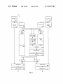


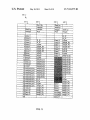
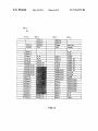

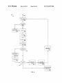

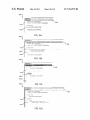
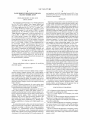
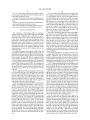
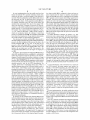
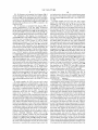
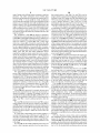
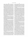


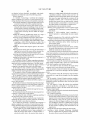
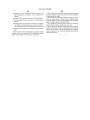


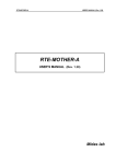


![TR4W User Manual [English Version]](http://vs1.manualzilla.com/store/data/005798737_1-5ae60a1fb1429eafa2ca68266ac47e3b-150x150.png)


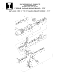
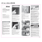
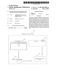

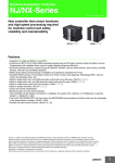

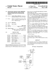

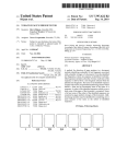
![TR4W User Manual [English Version]](http://vs1.manualzilla.com/store/data/005728234_1-e27c4fea1c6d513d6e0fdc1451ef66f1-150x150.png)