1
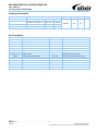
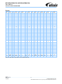
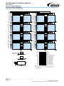
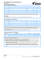
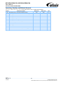
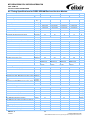
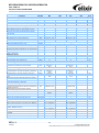
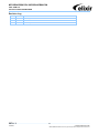
M2Y2G64CB8HC5N / M2Y2G64CB8HC9N 2GB: 256M x 64 Unbuffered DDR3 SDRAM DIMM Input/Output Functional Description Symbol Type Polarity Function CK0, CK1 , Input Cross point The system clock inputs. All address and command lines are sampled on the cross point of the rising edge of CK and falling edge of . A Delay Locked Loop (DLL) circuit is driven from the clock inputs and output timing for read operations is synchronized to the input clock. CKE0, CKE1 Input Active High Activates the DDR3 SDRAM CK signal when high and deactivates the CK signal when low. By deactivating the clocks, CKE low initiates the Power Down mode or the Self Refresh mode. , Input Active Low Enables the associated DDR3 SDRAM command decoder when low and disables the command decoder when high. When the command decoder is disabled, new commands are ignored but previous operations continue, Rank 0 is selected by ; Rank 1 is selected by , , Input Active Low When sampled at the positive rising edge of CK and falling edge of , signals , , define the operation to be executed by the SDRAM. ODT0, ODT1 Input Active High Asserts on-die termination for DQ, DM, DQS, and signals if enabled via the DDR3 SDRAM mode register. DM0 – DM8 Input Active High The data write masks, associated with one data byte. In Write mode, DM operates as a byte mask by allowing input data to be written if it is low but blocks the write operation if it is high. In Read mode, DM lines have no effect. The data strobes, associated with one data byte, sourced with data transfers. In Write mode, the data strobe is sourced by the controller and is centered in the data window. In Read mode, the data strobe is sourced by the DDR3 SDRAM and is sent at the leading edge of the data window. signals are complements, and timing is relative to the cross point of respective DQS and . If the module is to be operated in single ended strobe mode, all signals must be tied on the system board to VSS and DDR3 SDRAM mode registers programmed appropriately. DQS0 – DQS8 – I/O Cross point BA0, BA1, BA2 Input - Selects which DDR3 SDRAM internal bank of four or eight is activated. Input - During a Bank Activate command cycle, defines the row address when sampled at the cross point of the rising edge of CK and falling edge of . During a Read or Write command cycle, defines the column address when sampled at the cross point of the rising edge of CK and falling edge of . In addition to the column address, AP is used to invoke autoprecharge operation at the end of the burst read or write cycle. If AP is high, autoprecharge is selected and BA0-BAn defines the bank to be precharged. If AP is low, autoprecharge is disabled. During a Precharge command cycle, AP is used in conjunction with BA0-BAn to control which bank(s) to precharge. If AP is high, all banks will be precharged regardless of the state of BA0-BAn inputs. If AP is low, then BA0-BAn are used to define which bank to precharge. A0 – A9 A10/AP A11 A12/ A13 DQ0 – DQ63 Input - Data Input/Output pins. VDD, VDDSPD, VSS Supply - Power supplies for core, I/O, Serial Presence Detect, Temp sensor, and ground for the module. VREFDQ, VREFCA Supply - Reference voltage for SSTL15 inputs SDA I/O - This is a bidirectional pin used to transfer data into or out of the SPD EEPROM and temp sensor. A resistor must be connected from the SDA bus line to VDDSPD on the system planar to act as a pull up. SCL Input - This signal is used to clock data into and out of the SPD EEPROM and Temp sensor. SA0 – SA2 Input - Address pins used to select the Serial Presence Detect and Temp sensor base address. Output - The pin is reserved for use to flag critical module temperature. Input - This signal resets the DDR3 SDRAM REV 1.1 01/2010 4 © NANYA TECHNOLOGY CORP. NANYA TECHNOLOGY CORP. reserves the right to change Products and Specifications without notice.