1
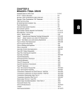
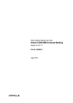
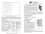
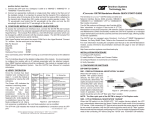
FlexSwitchTM 8U
Model 6500-FK
Replacement Kit
User Manual
140 Technology #500, Irvine, CA 92618
Phone: (949) 250-6510; Fax: (949) 250-6514
Table of Contents
1.0
1.1
2.0
2.1
2.2
2.4
3.0
3.1
3.2
3.3
3.3.1
4.0
4.1
5.0
INTRODUCTION .................................................................... 3
General Description ............................................................. 3
INSTALLATION ...................................................................... 3
Chassis Installation .............................................................. 3
Module Installation ............................................................... 3
UTP Installation .................................................................... 4
CONFIGURATION ................................................................. 4
AC Site Preparation .............................................................. 4
AC Powered Chassis Mounting .......................................... 4
Configuring the DIP-Switches............................................. 5
Switch Module ...................................................................... 5
LED INDICATORS ................................................................. 7
Switch Module ...................................................................... 7
SPECIFICATIONS .................................................................. 8
Page 2
1.0
INTRODUCTION
1.1
General Description
The 6500-FK is the direct replacement for the discontinued FlexSwitch Model
600XC 8U. The 6500-FK replacement kit consists of two iConverter 4Tx
Switch Modules installed in a iConverter 2-Module chassis.
The 6500-FK provides eight auto-negotiating 10/100 UTP ports with autocrossover that enables easy attachment to hubs, switches and workstations.
The 6500-FK provides on-board DIP-Switches for manual configuration of
Port 1 and 2 on each 4-Port Switch Module.
2.0
INSTALLATION
2.1
Chassis Installation
The 6500-FK is designed to accommodate wall-mounting and tabletop
installations. For wall-mounting, the 8249-0 Wall-Mount kit (sold separately)
is designed to attach the chassis to a wall, backboard or other flat surfaces.
For tabletop installations, place the unit on a flat level surface. Attach the
rubber feet to the bottom of the chassis to prevent the unit from sliding. Make
sure the unit is placed in a safe, dry and secure location.
For external power installation and configuration, see section 3.0.
2.2
Module Installation
The modules are pre-installed in the 2-Module chassis with the backplane
enabled on both modules. If the modules are removed, carefully slide the
module into the open slot. Align the module with the installation guides and
ensure that the module is firmly seated against the backplane. Secure the
module by fastening the front panel thumbscrew (push in and turn clockwise
to tighten) to the chassis front.
Page 3
2.4
UTP Installation
Connect the UTP port via a Category 5 cable to a 10Base-T or 100Base-Tx
Ethernet device.
3.0
CONFIGURATION
3.1
AC Site Preparation
•
Power source should be available within 5 ft. of the chassis and installed
per the National Electrical Code ANSI/NFPA-70.
•
This equipment requires a 100-240VAC, 0.5Amp, 50/60Hz power outlet.
Appropriate overloading protection should be provided on the AC power
source outlets utilized.
•
The operating temperature of this equipment is 0 to 50 degrees C. If installed
in a closed or multi-module rack assembly, the operating ambient
temperature of the rack must not exceed the maximum rated 50 degrees C.
•
Installation of the equipment should be such that the air flow in the front
and back of the chassis is not compromised or restricted.
•
Never use this equipment to carry any weight except its own. Never use it
as a shelf to support the weight of other equipment.
3.2
AC Powered Chassis Mounting
Attach the AC power cord to the back of the Power Receptacle and plug into
the AC outlet. Any installed modules will illuminate the power LED.
Page 4
3.3
Configuring the DIP-Switches
The 6500-FK has been pre-configured with Auto-Negotiation enabled for plug
and play easy of use. However, the iConverter Switch Modules offer additional
configuration flexibility.
3.3.1
Switch Module
Each 4-Port Switch Module has been pre-configured for Auto-Negotiation.
On-board DIP-Switches are available to manually configure Port 1 and 2 of
each module. The figure indicates the factory default settings.
__
BP A EN
__
BP B EN
MAN
AN
10
100
P2
FD
MAN
(Port 2)
HD
P1
100
(Port 1)
AN
10
HD
FD
(Left Position)
(Right Position)
4 Port Switch Module DIP-Switch
Backplane Port A Enable/Disable “BP A EN” DIP-Switch
This DIP-Switch must be in the LEFT position (factory default) for the module
to operate correctly. The switch provides backplane connectivity with the
other switch module.
Backplane Port A Enable/Disable “BP B EN” DIP-Switch
This DIP-Switch must be in the LEFT position (factory default) for the module
to operate correctly. The switch provides backplane connectivity with the
other switch module.
UTP Auto-Negotiate/Manual “AN / MAN” DIP-Switch (Port 1 or Port 2)
When this DIP-Switch is in the UTP Auto-Negotiate “AN” position (factory
default), the UTP port automatically determines the speed and duplex mode of
the connecting UTP device. If the connecting UTP device cannot provide the
proper signal to indicate its own mode of operation, this DIP-Switch should be
set to the UTP Manual mode “Man” position. Manual mode requires manually
configuring the UTP port to match the speed and the duplex mode of the
connecting UTP device using the “10/100” and UTP “FDX/HDX” DIP-Switches.
When a UTP port is configured for Auto-Negotiation, the automatic crossover
detection is enabled for that particular UTP port. Automatic crossover detection
Page 5
is disabled when the UTP port is configured for manual negotiation.
UTP 10/100Mbps “10/100” DIP-Switch (Port 1 or Port 2)
When the UTP “AN/MAN” DIP-Switch (described above) is in the manual
“MAN” position, the “10/100” DIP-Switch determines the speed of operation
for the designated UTP port. Setting the “10/100” DIP-Switch to “100” position
(factory default) forces the UTP port to operate at 100Mbps. Setting this DIPSwitch to “10” position forces the UTP port to operate at 10Mbps. Adjust the
“10/100” DIP-Switch to match the speed of the connecting UTP device.
UTP Full/Half-Duplex “HD/FD” DIP-Switch (Port 1 or Port 2)
When the UTP “AN/MAN” DIP-Switch (described above) is in the manual
“MAN” position, the “HD/FD” DIP-Switch determines the duplex operation
mode for the UTP port. Setting the “HD/FD” DIP-Switch to UTP Full-Duplex
“FD” (factory default) position forces the UTP port to operate in Full-Duplex.
Setting this DIP-Switch to “HD” forces the UTP port to operate in HalfDuplex. Adjust the UTP Half/Full-Duplex DIP-Switch to match duplex mode
the connecting UTP device.
When the UTP “AN/MAN” DIP-Switch is in the Auto-Negotiate “AN” position
and the UTP Full/Half Duplex DIP-Switch is in the Full-Duplex “FD” position,
the UTP port Auto-Negotiates to Full or Half-Duplex. When in the HalfDuplex “HDX” position, the UTP port functions only in Half-Duplex.
Page 6
4.0
LED INDICATORS
4.1
Switch Module
Each 4-Port Switch Module has LED indicators to provide connection
information.
4 Port Switch Module
LED Function
Color
Off State
No Power
ON State
Power "Pwr"
Yellow
On: Module has Power
Port 1 "100 Link"
Green Not Linked at 100Mbps On: Port Linked at 100Mbps
Blinking: Data Activity
Port 1 "10 Link"
Green Not Linked at 10Mbps
Port 2 "100 Link"
Green Not Linked at 100Mbps On: Port Linked at 100Mbps
Blinking: Data Activity
Port 2 "10 Link"
Green Not Linked at 10Mbps
Port 3 "100 Link"
Green Not Linked at 100Mbps On: Port Linked at 100Mbps
Blinking: Data Activity
Port 3 "10 Link"
Green Not Linked at 10Mbps
Port 4 "100 Link"
Green Not Linked at 100Mbps On: Port Linked at 100Mbps
Blinking: Data Activity
Port 4 "10 Link"
Green Not Linked at 10Mbps
On: Port Linked at 10Mbps
Blinking: Data Activity
On: Port Linked at 10Mbps
Blinking: Data Activity
On: Port Linked at 10Mbps
Blinking: Data Activity
On: Port Linked at 10Mbps
Blinking: Data Activity
4 Port Switch Module LED Indicators
Page 7
5.0
SPECIFICATIONS
Description
8 Port 10/100 Auto-Sensing Switch
Protocols
10Base-T, 100Base-Tx,
with 1536 bytes max. frame size
UTP Cable Type
EIA/TIA 568A/B
Category 5 and higher
UTP Connector Type
RJ45
DIP-Switches
UTP Port 1 and 2: AN/MAN, 10/100, FDX/HDX
Power Requirements
100 - 240 VAC @ 0.5A/0.4A, 50/60Hz
Dimensions
W:6.7" x D:5.51" x H:1.87"
Weight
3.0 lbs
Compliances
UL, CE, FCC CLass A, NEBS Level 3
Temperature
Operating: 0 to +50 C
Storage: -40 to +80 C
Humidity
(non-condensing)
< 95%
Altitude (operational)
< 4000m (13,000 ft)
Warning
The operating description in this Instruction Manual is for use by qualified
personnel only. To avoid electrical shock, do not perform any servicing of this
unit other than that contained in the operating instructions, unless you are
qualified and certified to do so by Omnitron Systems Technology, Inc.
Caution
All user-required operations can be performed without opening the unit. Never
attempt to open or remove the cover or tamper with the unit. There are no user
replaceable or serviceable parts in this unit. Equipment is not intended to be
installed and used in a place (home, school, or public area) accessible to the
general population.
Warranty
This product is warranted to the original purchaser against defects in material
and workmanship for a period of TWO YEARS from the date of shipment. A
LIFETIME warranty may be obtained by the original purchaser by
REGISTERING this product with Omnitron within 90 days from the date of
shipment. TO REGISTER, COMPLETE AND MAIL OR FAX THE
ENCLOSED REGISTRATION FORM. Or you may register your product on
Page 8
the Internet at http://www.omnitron-systems.com. During the warranty period,
Omnitron will, at its option, repair or replace a product which is proven to be
defective.
For warranty service, the product must be sent to an Omnitron designated
facility, at Buyer’s expense. Omnitron will pay the shipping charge to return
the product to Buyer’s designated US address using Omnitron’s standard
shipping method.
Limitation of Warranty
The foregoing warranty shall not apply to defects resulting from improper or
inadequate use and/or maintenance of the equipment by Buyer, Buyer-supplied
equipment, Buyer-supplied interfacing, unauthorized modifications or
tampering with equipment (including removal of equipment cover by personnel
not specifically authorized and certified by Omnitron), or misuse, or operating
outside the environmental specification of the product (including but not limited
to voltage, ambient temperature, radiation, unusual dust, etc.), or improper
site preparation or maintenance.
No other warranty is expressed or implied. Omnitron specifically disclaims
the implied warranties of merchantability and fitness for any particular purpose.
Exclusive Remedies
The remedies provided herein are the Buyer’s sole and exclusive remedies.
Omnitron shall not be liable for any direct, indirect, special, incidental, or
consequential damages, whether based on contract, tort, or any legal theory.
TECHNICAL SUPPORT
If you encounter problems with this product, contact Omnitron Technical
Support.
Phone:
800-675-8410
949-250-6510
Fax:
949-250-6514
Address:
Omnitron Systems Technology, Inc.
140 Technology Dr., #500
Irvine, CA 92618
Email:
URL:
[email protected]
http://www.omnitron-systems.com
Form: 040-06500-FK1 A 02/07
Page 9