1
position before insertion.
c. Connect the UTP port via a Category 5 cable to a 10BASE-T, 100BASE-TX or
1000BASE-T Ethernet device.
d. Connect an appropriate multimode or single-mode fiber cable to the fiber port of
the installed module. It is important to ensure that the transmit (TX) is attached to
the receive side of the device at the other end and the receive (RX) is attached to
the transmit side. Single-fiber (SF) media converter models operate in pairs. The
TX wavelength must match the RX wavelength at the other end and the RX
wavelength must match the TX wavelength at the other end.
3) CONFIGURE MODULE VIA COMMAND LINE INTERFACE
To access the Command Line Interface (CLI), connect the GX/TM RS-232 Console
Port to the COM port of a computer equipped with terminal emulation software such as
HyperTerminal. The Console Port (DCE) is a mini DIN-6 female connector which can
be changed to a DB-9 connector with the included adapter. The GX/TM Console Port
is a standard asynchronous serial interface.
Start HyperTerminal and select the correct COM Port in the HyperTerminal “Connect
To:” window. Set the serial port to the following:
Bits Per Second
57,600
Stop Bits
1
Data Bits
8
Parity
NONE
Hardware Flow Control
NONE
Once connected, press <ENTER> to bring up a command line prompt on the attached
PC.
The CLI interface allows for the detailed configuration of the module. It is recommended
to configure the module with an IP address associated with the attached network.
Also, SNMP traphost address should be configured if the module is managed with an
SNMP-based Management System. See the GX/TM User Manual for complete
information.
4) VERIFY OPERATION
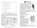
Once the module has been
LED Function
Color
Off State
On / Blinking State
installed and configured per
"Legend"
steps 1 - 3, verify the module is
Power "Pwr"
Amber No power
On: Module has power
operational by viewing the LED
1000Mbps
On: Fiber Link
Fiber Optics
Green No Fiber Link
indicators.
Blinking: Fiber Data Activity
"FO"
The Power LED indicates the
UTP port
Not linked at
On: UTP linked at 100Mbps
100Mbps
Green
100Mbps
Blinking: UTP Data Activity
modules is receiving power.
"100"
The Fiber Optic link LED
UTP port
Not linked at
On: UTP linked at 1000Mbps
1000Mbps
Green
1000Mbps
Blinking: UTP Data Activity
"1000"
indicates the fiber optic
UTP
port
connection
has
been
Not linked at
On: UTP linked at 10Mbps
10Mbps
Green
10Mbps
Brinking: UTP Data Activity
"100" + "1000"
established. Verify the Link
Half-Duplex when
UTP port
Mode selection is set to Link
On: Full-Duplex when any UTP link
Full-Duplex
Green any UTP link is
is active
"FDX"
active
Segment (LS). Until a stable link
is established, leave the Link
Figure D: LED Indicators
Mode configured for LS. After a
Link presence is established, the Link Mode selection can be modified.
The UTP link LED indicates the module has established a connection across its UTP
Form 040-08920-001 I 12/07
port.
Omnitron Systems Technology * 140 Technology Dr. * #500 * Irvine, CA 92618
949.250.6510 tel * 949.250.6514 fax * www.omnitron-systems.com
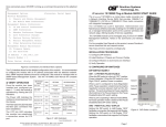
iConverter GX/TM Standalone Module QUICK START GUIDE
The Omnitron iConverter® GX/TM media converter and
Network Interface Device (NID) provides 10BASE-T,
100BASE-TX or 1000BASE-T UTP to 1000BASE-FX
fiber media conversion.
The GX/TM conforms to Ethernet in the First Mile (EFM)
fiber standards to support Fiber-to-the-X (FTTX)
Metropolitan access and Enterprise LAN networks. Built-in Operation, Administration
and Maintenance (OAM) functionality enables the GX/TM to operate as a managed
copper demarcation point at the customer premises and network edge, offering Quality
of Service capabilities.
The GX/TM can be managed using Omntron’s NetOutlookTM SNMP Management
Software, 3rd Party SNMP Client, Telnet or the Command Line Interface (CLI).
For more information including the complete User Manual on the GX/TM Standalone
module, access Omntron’s documentation download web page to view all relevant
documents:
http://www.omnitron-systems.com/downloads.php
INSTALLATION PROCEDURE
1) Configure DIP-Switches
2) Install Module in Chassis and Connect Cables
3) Configure Module via Command Line Interface
4) Verify Operation
1) CONFIGURE DIP-SWITCHES
DIP-SWITCH BANK 1
SW1 - FIBER AUTO/MANUAL NEGOTIATION “AN MAN”
When this DIP-switch is in the
DOWN “AN” position (factory
Up
default), the fiber optic port
Bank 2
automatically determines the SW3
SW8
duplex and pause modes of the
connecting fiber optic device.
Bank 1
Down
If the connecting fiber optic
SW1
SW8
device cannot provide the
proper signal to indicate its own
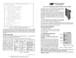
Figure A: DIP-Switch Locations
mode of operation, the DIPswitch should be set to the UP fiber optic “Man” position.
NOTE: The fiber optic port of the GX/TM is always in Full-Duplex mode.
SW2 - UTP AUTO/MANUAL NEGOTIATION “AN/MAN”
When this DIP-switch is in the DOWN UTP “AN” position (factory default), the UTP
port automatically determines the Speed, Duplex and Pause mode of the connecting
UTP device. If the connecting UTP device cannot provide the proper signal to indicate
its own mode of operation, then the DIP-switch should be set to the UP “Man” position.
Manual mode requires manually configuring the UTP port to match the Speed and Duplex
mode of the connecting UTP device using the “10/100” and “FDX/HDX” DIP-switches.
SW3 - UTP SPEED GIGABIT/10-100 “1000/10-100”
When the “1000/10-100” DIP-switch is in the “1000” position (factory default), the
UTP port always operates in 10/100/1000Mbps Auto-Negotiation mode. The UTP
port auto-negotiates to a speed of 10Mbps, 100Mbps or 1000Mbps with the
connected UTP device. In this mode, the UTP “AN/Man” and UTP “100/10” DIP-switches
have no effect.
When the “1000/10-100” DIP-switch is in the “10-100” position and the UTP “AN/Man”
DIP-switch is in the “Man” position, the UTP port operates at the Speed, Duplex and
Pause modes set by the “100/10”, “FDX/HDX” and “Off/Pause” DIP-switches.
When the “1000/10-100” DIP-switch is in the “10-100” position and the UTP “AN/Man”
DIP-switch is in the “AN” position, the UTP port maximum auto-negotiation setting
for the Speed, Duplex and Pause mode is determined by the “100/10,” “FDX/HDX”
and “Off/ Pause” DIP-switches.
SW4 - UTP 100/10MBPS “100/10”
When the UTP “AN/Man” DIP-switch (described above) is in the manual “Man” position,
the “100/10" DIP-switch determines the speed of operation for the UTP port. Set the
“100/10” DIP-switch to match the speed of the connected UTP device.
SW5 - UTP FULL/HALF DUPLEX “FDX/HDX”
Setting the UTP Full/Half-Duplex DIP-switch to the UTP “FDX” position (factory default)
forces the UTP port to operate in Full-Duplex. Setting this DIP-switch to UTP “HDX”
forces the UTP port to operate in Half-Duplex. Adjust the UTP Full/Half-Duplex DIPswitch to match the duplex mode of the connected UTP device.
SW6, SW7, SW8 - LINK MODES
These three DIP-switches configure the link mode settings. The following table details
possible Link Mode DIP-switch configurations.
Switch
Down
(Factory Default)
SW1
Up
SW6
SW7
SW8
Link Mode Selection
AN:
Fiber Auto-Negotiation
SW2 AN:
UTP Auto-Negotiation
Man:
Fiber Manual Negotiation
Man:
UTP Manual
Down Down Down Link Segment (LS)
(Factory Default)
Up Down Down Link Propagate (LP)
SW3
1000:
UTP 1000Mbps
10-100:
UTP 10-100Mbps
Down
Up
Down Remote Fault Detect + Link
Segment (RFD + LS)
SW4
100:
UTP 100Mbps
10:
UTP 10Mbps
Up
Up
Down Remote Fault Detect + Link
Propagate (RFD + LP)
SW5
FDX:
UTP Full-Duplex
HDX:
UTP Half-Duplex
SW6
SW7
See Link Mode Selection
SW8
Down Down
Up
Symmetrical Fault Detect (SFD)
Up
Down
Up
Illegal Setting
Down
Up
Up
Illegal Setting
Up
Up
Up
Illegal Setting
Figure B: DIP-Switch Bank 1
DIP-SWITCH BANK 2
SW1, SW2 - NOT VISIBLE
SW3 - PAUSE DISABLE/ENABLE “OFF/PAUSE”
When the UTP port is operating in Auto-Negotiation mode, it advertises for Pause
based on the Pause Disable/Enable “Off/Pause” DIP-Switch setting. Setting the Pause
DIP-switch to the “Off” position (factory default) forces the UTP port to negotiate to No
Pause. Setting this DIP-switch to the “Pause” position allows the UTP port to negotiate
to Symmetrical Pause, Asymmetrical Pause or No Pause mode. When the UTP port
is operating in Manual mode, Pause is disabled.
SW5 - UTP 10/100 AUTO/MANUAL CROSSOVER “AX/MANX”
The 10/100 Auto Crossover feature is
Up
only available when the UTP port is Switch Down (Factory Default)
SW3 Off:
Pause:
operating in 10/100 Auto-Negotiation
Pause Disable
Pause Enable
SW4 Reserved
Reserved
mode.
SW5 Auto:
Man:
When “AX/MANX” DIP-switch is set to
UTP Auto Crossover
UTP Manual Crossover
SW6 =:
X:
“AX” (factory default), the 10/100 UTP
Manual UTP Straight-Through Manual UTP Crossover
Auto Crossover feature is enabled.
SW7 Reserved
Reserved
SW8 Reserved
Reserved
When it is set to “MANX”, the UTP
Manual Crossover DIP-switch is
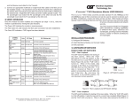
Figure C: DIP-Switch Bank 2
enabled to allow the user to manually
set either a Crossover or Straight-through connection.
SW6 - UTP MANUAL CROSSOVER “=/X”
When this DIP-switch is set to “MANX”, the UTP Manual Crossover Switch is enabled.
Set this DIP-switch to “=” (factory setting) when connecting the UTP port to a workstation,
or set it to “X” when connecting to a hub or switch. Only use this setting in 10/100Mbps
Manual negotiation mode.
SW4, SW7, SW8 - RESERVED
These DIP-switches are for factory use only and must always remain in the LEFT
position (factory default).
2) INSTALL MODULE IN CHASSIS AND CONNECT CABLES
a. The GX/TM Network Interface Device (NID) is available in tabletop and wall-mounting
models. For wall-mounting, attach the NID to a wall, backboard or other flat surfaces.
For tabletop installations, place the unit on a flat level surface. Attach the rubber
feet to the bottom of the NID to prevent the unit from sliding. Make sure the unit is
placed in a safe, dry and secure location.
To power the unit using the AC/DC adapter, connect the AC/DC adapter to the AC
outlet. Then connect the barrel plug at the end of the wire on the AC/DC adapter to
the 2.5mm DC barrel connector (center-positive) on the chassis. Confirm that the
unit has powered up properly by checking the power status LED located on the
front of the unit.
To power the unit using a DC power source, prepare a power cable using a twoconductor insulated wire (not supplied) with a 14 AWG gauge minimum. Cut the
power cable to the length required. Strip approximately 3/8 of an inch of insulation
from the power cable wires. Connect the power cables to the unit by fastening the
stripped ends to the DC power connector.
Connect the power wires to the DC power source. The Power LED should indicate
the presence of power.
WARNING: Note the wire colors used in making the positive and negative
connections. Use the same color assignment for the connection at the DC
power source.
NOTE: If mounting with a safety ground attachment, use the safety ground
screw at the rear of the unit.
b. When using a GX/TM SFP model (8939-0), insert the SFP Fiber transceiver into
the Port 1 SFP receptacle on the GX/TM.
NOTE: The release latch of the SFP Fiber transceiver must be in the closed