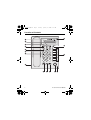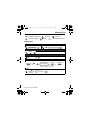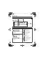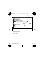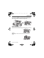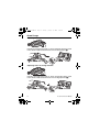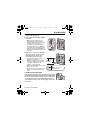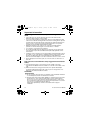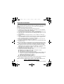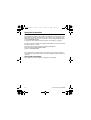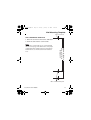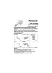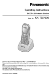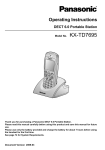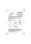
1
NT321M_QRG.fm
Page 1
Tuesday, January 15, 2008
4:51 PM
Quick Reference Guide
IP Proprietary Telephone
Model No. KX-NT321
Thank you for purchasing an IP Proprietary Telephone (IP-PT).
Please read this manual carefully before using this product and save
this manual for future use.
For more details, please refer to the manuals of the PBX.
Accessories (included)
Handset
Handset Cord
One
Screws
Wall Mounting
Adaptor
One
One
Stand
Two
One
This model supports the following PBX versions and CODEC types:
KX-TDA50: PSMPR Software File Version 4.0000 or later
KX-TDA100/KX-TDA200: PMPR Software File Version 5.0000 or later
KX-TDA600: PLMPR Software File Version 5.0000 or later
KX-TDE100/KX-TDE200: PMMPR Software File Version 1.0000 or later
CODEC: G.729A, G.711, G.722 *1
*1
G.722 is only available for KX-TDE100/KX-TDE200.
Document Version 2008-05
NT321M_QRG.fm
Page 2
Tuesday, January 15, 2008
4:51 PM
Location of Controls
Location of
Controls
P
A
B
C
O
D
E
F
G
N
H
I
2
J
K
L M
Document Version 2008-05
NT321M_QRG.fm
Page 3
Tuesday, January 15, 2008
4:51 PM
Location of Controls
A LCD (Liquid Crystal
Display)
B AUTO DIAL/STORE: Used
for System/Personal Speed
Dialing or storing program
changes.
C AUTO ANS (Auto Answer)/
MUTE: Used to receive an
incoming call in hands-free
mode or mute the
microphone/handset during a
conversation.
D INTERCOM: Used to make or
receive intercom calls.
E MESSAGE: Used to leave a
message waiting indication or
call back the party who left
the message waiting
indication.
F REDIAL: Used to redial the
last dialed number.
G TRANSFER: Used to transfer
a call to another party.
H Headset Jack
I FLASH/RECALL: Used to
disconnect the current call
and make another call without
hanging up.
Document Version 2008-05
J HOLD: Used to place a call
on hold.
K SP-PHONE
(Speakerphone): Used for
performing hands-free
operations.
L Navigator Key: Used to
adjust the volume and the
display contrast or select
desired items.
M Microphone: Used for
hands-free conversations.
N Flexible CO Buttons: Used
to seize a CO line or perform
a feature that has been
assigned to the key.
O PROGRAM: Used to enter
and exit the personal
programming mode.
P Message/Ringer Lamp:
When you receive an
intercom call, the lamp
flashes green, and on an
outside call, the lamp flashes
red. When someone has left
you a message, the lamp
stays on red.
3
NT321M_QRG.fm
Page 4
Tuesday, January 15, 2008
4:51 PM
Settings
Settings
Speaker volume While in a hands-free conversation
Handset/Headset While using the handset or
headset
volume*1
Ringer volume
Press Up to increase
While on-hook or receiving a call or Down to decrease
the volume.
LCD Contrast
While on-hook
PROGRAM
AUTO DIAL
AUTO DIAL
STORE
STORE
PROGRAM
Ring Tone
(CO)
PROGRAM
*2
OR
INTERCOM
AUTO DIAL
PROGRAM
STORE
Press 2 times.
LCD Backlight
While on-hook
Automatic
PROGRAM
AUTO DIAL
Always ON
STORE
Always OFF
AUTO DIAL
PROGRAM
STORE
*1
If you hear your own voice through the handset or headset, decrease the
volume.
*2
The ring tone pattern of patterns 09 to 30 is the same as pattern 01.
4
Document Version 2008-05
NT321M_QRG.fm
Page 5
Tuesday, January 15, 2008
4:51 PM
Features List
Features List
Icon Meanings
(CO)
= Flexible CO button
= Feature number
= Off-hook
= Talk
C. Tone
= On-hook
= Confirmation Tone
Making Calls
Calling
To an extension
To an outside party
extension no.
(CO)
outside phone no.
Redial
REDIAL
Quick Dialing
quick dial no.
One-touch Dialing
To store
PROGRAM
(CO)
desired no.*
(max. 32 digits)
AUTO DIAL
PROGRAM
STORE
* Enter CO line access number
before outside phone number.
To dial
assigned as a
(One-touch One-touch Dialing
Dialing)
button
Document Version 2008-05
5
NT321M_QRG.fm
Page 6
Tuesday, January 15, 2008
4:51 PM
Features List
Personal Speed Dialing
To store
personal speed
dial no. (2 digits)
desired no.*
(max. 32 digits)
C. Tone
* Enter CO line access number
before outside phone number.
To dial
AUTO DIAL
personal speed dial no. (2 digits)
STORE
System Speed Dialing
To dial
AUTO DIAL
system speed dial no. (3 digits)
STORE
Doorphone Call
doorphone no. (2 digits)
C. Tone
During a Conversation
Call Hold
To hold
To retrieve a call at the holding extension
HOLD
(CO)
C. Tone
/
INTERCOM
To retrieve an outside call from another extension
(CO)
Call Transfer
extension no.
TRANSFER
C. Tone
6
(CO)
To an extension
outside
phone no.
To an outside
party
Document Version 2008-05
NT321M_QRG.fm
Page 7
Tuesday, January 15, 2008
4:51 PM
Features List
Useful Features
Multiple Party Conversation
To add other parties during a conversation (i.e., conference)
assigned as a
(Conference) Conference
button
C. Tone
desired
phone no.
assigned as a
(Conference) Conference
C. Tone
button
Talk to the
new party.
Talk with
multiple parties.
To leave a conference
assigned as a
C. Tone
(Conference) Conference
button
Setting the Telephone According to Your Needs
Do Not Disturb
Both Calls
Set
Outside Calls
Cancel C. Tone
Intercom Calls
Timed Reminder
To set
12 H
hour/minute
(4 digits)
24 H
AM
PM
hour/minute
(4 digits)
1 time
daily
C. Tone
To cancel
To stop or answer the ring back
INTERCOM
C. Tone
Document Version 2008-05
/
7
NT321M_QRG.fm
Page 8
Tuesday, January 15, 2008
4:51 PM
Features List
Before Leaving Your Desk
Call Forwarding
Both Calls
Outside Calls
Intercom Calls
All calls
extension no.
Busy
No answer
Busy/
No answer
OR
CO line
access no.
C. Tone
outside
phone no.
Cancel
Making Use of the Voice Mail Service
Listening to a message
From your own extension
VPS extension no.
Mailbox Password*
* If you have no password, you can skip
the last step.
KX-TVA series
Listen to Message
Deliver Message
Mailbox Management
Automated Attendant
Message Notification
From someone else’s extension
VPS extension no.
Other Features
End Call
KX-TVS series
Listen to Message
mailbox no.
Deliver Message
Mailbox Password*
Check Mailbox Distribution
* If you have no password, you can skip
the last step.
Automated Attendant
Mailbox Management
Other Features
End Call
8
Document Version 2008-05
NT321M_QRG.fm
Page 9
Tuesday, January 15, 2008
4:51 PM
Features List
Leaving a message
VPS extension no.
From your own extension
Mailbox Password*
From someone else’s extension
mailbox no.
Mailbox Password*
* If you have no password, you can skip the last step.
Enter the desired mailbox number
Leave
a message
To send the message immediately
(KX-TVA series)
(KX-TVS series)
Follow the guidance
To set the delivery time
During playback
Repeat Voice Guidance
Exit
• Consult your dealer or the network administrator for more details
regarding feature numbers.
• It is possible to assign flexible CO buttons as feature buttons.
• Control panel/button names and descriptions can be found in “Location of
Controls” on page 2.
Document Version 2008-05
9
NT321M_QRG.fm
Page 10
Tuesday, January 15, 2008
4:51 PM
Connection
Connection
<Back view>
To a Switching Hub.
To a PC.
Optional AC adaptor
(not included).
Clamp
AC adaptor
Headset
Recommended: KX-TCA86, KX-TCA92
Do not use a KX-T7090 headset.
For extra orders for the accessories, call toll-free: 1-800-332-5368
PC connection
• Use a straight CAT 5 (or higher) Ethernet cable (not included) that is 6.5
mm (1/4 in) in diameter or less.
• For further information on the connection to a PC, refer to the
documentation provided for the PBX.
Switching Hub connection
• Use a straight CAT 5 (or higher) Ethernet cable (not included) that is 6.5
mm (1/4 in) in diameter or less.
AC adaptor
• Use a Panasonic AC adaptor KX-A239 (PQLV206).
• The AC adaptor is used as the main disconnect device. Ensure that the
AC outlet is located near the unit and is easily accessible.
CAUTION:
When connecting cables
• Ensure that the Ethernet cables and the AC adaptor cord are
clamped to prevent damage to the connectors.
• Cables may be routed either upwards or downwards by using
the appropriate cable clamp located on the back of the unit.
When connecting a headset and AC adaptor
• Ensure that the headset cord and the AC adaptor cord are
wound around the hook to prevent damage to the connectors.
10
Document Version 2008-05
NT321M_QRG.fm
Page 11
Tuesday, January 15, 2008
4:51 PM
Stand Usage
Stand Usage
Attaching the Stand
Place the catches (A) of the stand into hooks located in the unit.
Gently push the stand in the direction indicated until it locks into
place. The stand will be mounted in the high position.
A
Removing the Stand
Hold the stand with both hands.
Gently rotate the stand in the direction indicated until it is released.
Cabling
When using the stand, ensure that the cables are clamped as
shown.
Document Version 2008-05
11
NT321M_QRG.fm
Page 12
Tuesday, January 15, 2008
4:51 PM
Stand Usage
Adjusting from High to Low Position
Hold the stand with both hands as shown and gently push the stand
in the direction indicated until it locks into the low position (B).
Adjusting from Low to High Position
Hold the stand with both hands as shown and gently pull the stand
in the direction indicated until it locks into the high position (A).
A
12
Document Version 2008-05
NT321M_QRG.fm
Page 13
Tuesday, January 15, 2008
4:51 PM
Wall Mounting
Wall Mounting
1. Remove the stand if it is attached. For information on removing the
stand, refer to page 11.
2. Attach the wall mounting adaptor
as shown.
• Make sure the cables are not
pinched by the wall mounting
adaptor. When running the cables
from the top of the unit, look
through the opening in the wall
mounting adaptor to confirm that
the cables are not being pinched.
• Slide the wall mounting adaptor in
the direction indicated until it locks
into place.
3. Drive the 2 screws into the wall
either 83 mm (3-1/4 in) or 100
mm (3-15/16 in) apart, and
mount the unit on the wall.
• You can find a wall mounting
83 mm
template on page 19.
(3-1/4 in)
• Make sure that the wall that the
100 mm
(3-15/16 in)
unit will be attached to is strong
enough to support the unit
(approx. 1.5 kg [3.31 lb]).
• Make sure the cables are securely
Washer
fastened to the wall.
Drive the screw
• When this unit is no longer in use,
to this point.
make sure to detach it from the
wall.
Locking the Handset Hook
Pull down the handset hook until it locks to prevent
the handset from falling off the handset cradle when
the unit is mounted to a wall or set at a high angle.
To temporarily place the handset down during a
conversation, hook it over the top edge of the unit
as shown.
Document Version 2008-05
13
NT321M_QRG.fm
Page 14
Tuesday, January 15, 2008
4:51 PM
Important Information
Important Information
When using a KX-NT321 IP-PT, keep the following conditions in
mind.
• If the unit does not operate properly, disconnect the unit from the
Ethernet cable and then connect again.
• If you are having problems making calls, disconnect the Ethernet cable
and connect a known working IP-PT. If the known working IP-PT operates
properly, have the defective IP-PT repaired by an authorized Panasonic
factory service center. If the known working IP-PT does not operate
properly, check the PBX and the Ethernet cable.
• Wipe the unit with a soft cloth. Do not clean the unit with abrasive
powders or with chemical agents such as benzene or thinner.
• Use only the correct Panasonic handset.
• Do not disassemble this unit. Dangerous electrical shock could result.
The unit must only be disassembled and repaired by qualified service
technicians.
• If damage to the unit exposes any internal parts, immediately disconnect
the cable or cord. If the power is supplied from the network to the IP-PT
[Power-over-Ethernet], disconnect the Ethernet cable. Otherwise,
disconnect the AC adaptor cord. Then return this unit to a service center.
• Never attempt to insert wires, pins, etc. into the vents or other holes of
this unit.
Take special care to follow the safety suggestions listed below.
Safety
1) The unit should only be connected to a power supply of the type
described in the Quick Reference Guide or as shown on the label on the
unit.
2) When left unused for a long period of time, the optional AC adaptor
should be unplugged from the AC outlet, if you are using Power-overEthernet, disconnect the Ethernet cable.
Installation
Environment
1) Do not use this unit near water, for example, near a bathtub, washbowl
or sink. Damp basements should also be avoided.
2) Keep the unit away from heating appliances and devices that generate
electrical noise, such as fluorescent lamps, motors and televisions.
These noise sources can interfere with the performance of the unit. It
also should not be placed in rooms where the temperature is less than
5 °C (41 °F) or greater than 40 °C (104 °F).
Allow 10 cm (3-15/16 in) clearance around the unit for proper
ventilation.
14
Document Version 2008-05
NT321M_QRG.fm
Page 15
Tuesday, January 15, 2008
4:51 PM
Important Information
Placement
1) Do not place heavy objects on top of this unit.
2) Care should be taken so that objects do not fall onto, and liquids are not
spilled into, the unit. Do not subject this unit to excessive smoke, dust,
moisture, mechanical vibration, shock or direct sunlight.
3) Place the unit on a flat surface.
WARNING:
TO PREVENT POSSIBLE FIRE OR ELECTRIC SHOCK, DO NOT EXPOSE
THIS UNIT TO RAIN OR MOISTURE.
THIS HANDSET EARPIECE IS MAGNETIZED AND MAY RETAIN SMALL
FERROUS OBJECTS.
DISCONNECT THIS UNIT FROM POWER OUTLET/THE ETHERNET
CABLE IF IT EMITS SMOKE, AN ABNORMAL SMELL OR MAKES
UNUSUAL NOISE. THESE CONDITIONS CAN CAUSE FIRE OR
ELECTRIC SHOCK. CONFIRM THAT SMOKE HAS STOPPED AND
CONTACT AN AUTHORIZED SERVICE CENTER.
IMPORTANT NOTICE:
• Under power failure conditions, the IP-PT may not operate. Please
ensure that a separate telephone, not dependent on local power, is
available for use in remote sites in case of emergency.
• For information regarding network setup of the IP-PT such as IP
addresses, please refer to the Installation Manual for the Panasonic PBX.
• If an error message is shown on your display, consult your dealer or the
network administrator.
• The firmware of the KX-NT321 is protected by copyright laws and
international treaty provisions, and all other applicable laws. It cannot be
reverse engineered, decompiled or disassembled.
When you ship the product:
Carefully pack and send it prepaid, adequately insured and preferably in the
original carton. Attach a postage-paid letter, detailing the symptom to the
outside of the carton.
DO NOT send the product to the Executive or Regional Sales offices. They
are NOT equipped to make repairs.
Product service:
Panasonic factory service centers for this product are listed in the service
center directory.
Consult your authorized Panasonic dealer for detailed instructions.
Document Version 2008-05
15
NT321M_QRG.fm
Page 16
Tuesday, January 15, 2008
4:51 PM
Important Information
Important Safety Instructions
When using this unit, basic safety precautions, including those below, should
always be followed to reduce the risk of fire, electric shock and injury to
persons.
1. Read and understand all instructions.
2. Follow all warnings and instructions marked on this unit.
3. Unplug this unit from the AC outlet before cleaning. Do not use liquid or
aerosol cleaners. Clean with a damp cloth.
4. Do not use the unit near water, for example, near a bathtub, kitchen sink,
or laundry tub, in a wet basement, or near a swimming pool.
5. Place this unit on a flat surface. Serious damage and/or injury may result
if the unit falls.
6. The unit should never be placed near or over a radiator or other heat
source.
7. This unit should be operated only from the type of power source indicated
on the unit label. If you are not sure of the type of power supply to your
home, consult your dealer or local power company.
8. Do not allow anything to rest on the power cord. Do not locate this unit
where the cord may be stepped on or tripped on.
9. To reduce the risk of fire or electric shock, do not overload AC outlets and
extension cords.
10.Do not insert objects of any kind into this unit through openings, as they
may touch dangerous voltage points or short out parts that could result in
a risk of fire or electric shock. Never spill liquid of any kind on the unit.
11.To reduce the risk of electric shock, do not disassemble this unit. Only
qualified personnel should service this unit. Opening or removing covers
may expose you to dangerous voltages or other risks. Incorrect
reassembly can cause electric shock.
12.Unplug this unit from the AC outlet and have the unit serviced by qualified
service personnel in the following cases:
A. When the power supply cord or plug is damaged or frayed.
B. If liquid has been spilled on the unit.
C. If the unit has been exposed to rain or water.
D. If the unit does not work normally by following the manual. Adjust only
controls covered by the manual. Improper adjustment may require
repair by an authorized service center.
E. If the unit has been dropped, or damaged.
F. If the unit’s performance deteriorates.
13.Avoid using a telephone (other than a cordless type) during an electrical
storm. There is a remote risk of electric shock from lightning.
14.Do not use the telephone in the vicinity of a gas leak to report the leak.
SAVE THESE INSTRUCTIONS
16
Document Version 2008-05
NT321M_QRG.fm
Page 17
Tuesday, January 15, 2008
4:51 PM
Important Information
FCC Information
F.C.C. REQUIREMENTS AND RELEVANT INFORMATION
This equipment has been tested and found to comply with the limits for a
Class B digital device, pursuant to Part 15 of the FCC Rules. These limits are
designed to provide reasonable protection against harmful interference in a
residential installation.
This equipment generates, uses, and can radiate radio frequency energy
and, if not installed and used in accordance with the instructions, may cause
harmful interference to radio communications. However, there is no
guarantee that interference will not occur in a particular installation. If this
equipment does cause harmful interference to radio or television reception,
which can be determined by turning the equipment off and on, the user is
encouraged to try to correct the interference by one or more of the following
measures:
• Reorient or relocate the receiving antenna.
• Increase the separation between the equipment and receiver.
• Connect the equipment into an outlet on a circuit different from that to
which the receiver is connected.
• Consult the dealer or an experienced radio/TV technician for help.
CAUTION:
To assure continued compliance with FCC rules, do not make any
unauthorized changes or modifications to this equipment would void the
user’s authority to operate this device.
When programming emergency numbers and/or making test calls to
emergency numbers:
1) Remain on the line and briefly explain to the dispatcher the reason for the
call before hanging up.
2) Perform such activities in the off peak hours, such as early morning hours
or late evenings.
FCC Declaration of Conformity
Trade Name: Panasonic
Model Number: KX-NT321
Responsible Party: Panasonic Corporation of North America
One Panasonic Way
Secaucus, NJ 07094 U.S.A.
Telephone No.: 1-800-211-PANA (7262)
This device complies with Part 15 of the FCC Rules.
Operation is subject to the following two conditions: (1) This device may not
cause harmful interference, and (2) this device must accept any interference
received, including interference that may cause undesired operation.
Document Version 2008-05
17
NT321M_QRG.fm
Page 18
Tuesday, January 15, 2008
4:51 PM
Important Information
Customer Information
This equipment complies with Part 68 of the FCC rules and the requirements
adopted by the ACTA. On the bottom of the cabinet of this equipment is a
label that contains, among other information, the following product identifier:
US: ACJKXNANKX-NT321
If requested, this number must be provided to the telephone company.
If trouble is experienced with this equipment KX-NT321, for repair or warranty
information, please contact:
Panasonic Service and Technology Company-BTS Center
415 Horizon Drive Bldg. 300 Ste. 350-B
Suwanee, GA 30024-3186
If the equipment is causing harm to the telephone network, the telephone
company may request that you disconnect the equipment until the problem is
resolved.
Hearing Aid Compatibility:
This telephone provides magnetic coupling for hearing aids.
18
Document Version 2008-05
NT321M_QRG.fm
Page 19
Tuesday, January 15, 2008
4:51 PM
Wall Mounting Template
Wall Mounting Template
One screw here
WALL MOUNTING TEMPLATE
1. Drive the screws into the wall as indicated.
2. Hook the unit onto the screw heads.
Note:
100 mm (3-15/16 in)
83 mm (3-1/4 in)
for base unit
Make sure to set the print size to correspond with
the size of this page. If the dimensions of the paper
output still deviate slightly from the measurements
indicated here, use the measurements indicated
here.
One screw at either point
Document Version 2008-05
19
NT321M_QRG.fm
Page 20
Tuesday, January 15, 2008
4:51 PM
Panasonic Consumer Electronics Company,
Division of Panasonic Corporation of North America
One Panasonic Way Secaucus, New Jersey 07094
Panasonic Puerto Rico, Inc.
San Gabriel Industrial Park Ave. 65 de Infantería, Km. 9.5
Carolina, Puerto Rico 00985
http://www.panasonic.com/csd
Copyright:
This material is copyrighted by Panasonic Communications Co., Ltd., and
may be reproduced for internal use only. All other reproduction, in whole or in
part, is prohibited without the written consent of Panasonic Communications
Co., Ltd.
© 2008 Panasonic Communications Co., Ltd. All Rights Reserved.
PSQX4664ZA-UU
KK0508YH0 (M) (Ver 0.02)