1
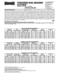
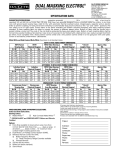
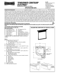
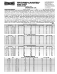
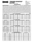
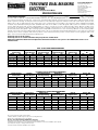
TENSIONED
DUAL MASKING
®
ELECTROL
Automatic Electric Projection Screen Model
SPECIFICATION DATA
DA-LITE SCREEN COMPANY, INC.
3100 North Detroit Street
Post Office Box 137
Warsaw, Indiana 46581-0137
Phone: 574-267-8101
800-622-3737
Fax: 574-267-7804
Toll Free Fax: 877-325-4832
www.da-lite.com
e-mail: [email protected]
SUGGESTED SPECIFICATIONS: ___________________ projection screen(s), ______________ (H) x _________________ ( W ) , e l e c t r i c a l l y
operated 120 volt (60 Hz) not more than 4.8 amp. Shall have two specially designed motors mounted inside two rollers, to be three
wire with ground quick reversal type, oiled for life, with automatic thermal overload cutout, integral gears, capacitor and an electric
brake to prevent coasting. To have pre-set limit switches to automatically stop picture surfaces in the “up” and “down” positions. The
fabric roller to be of rigid aluminum. The mask roller to be of rigid metal. Screen fabric to be seamless, flame retardant and mildew
resistant vinyl with black masking borders standard. Each side of the fabric to have tab guide cable system to maintain even lateral
tension and hold surface flat. To have masking fabric on sides to convert the screen to different aspect ratios. Bottom of fabric to be
inserted into an aluminum slat bar with added weight to maintain vertical tension on the screen surface. The ends of the slat to be
protected by heavy duty plastic caps enclosing a preset adjustable mechanism for screen tensioning. Bottom of each masking fabric
shall be formed into a pocket holding a flat steel bar. Case to be of wood and be finished with a black primer coat, ready to accept final
finish by others. To be complete with a three position control switch and a two position control switch in a two gang box with cover
plate. Screen to be listed by Underwriters’ Laboratories.
All viewing surfaces will be seamless.
All viewing surfaces are standard with black backing except Da-Tex® and Dual Vision.
Audio Vision, High Contrast Audio Vision and High Contrast Cinema Perf available in sizes up to 87" x 155" in HDTV Format and 87" x 161" in
Letterbox Format.
HDTV Format
HDTV
Viewing Area
Nominal Diagonal
HxW
Cm
In.
Cm
45" x 80"
114 x 203
92"
234
50" x 89" 127 x 226 102"
259
54" x 96" 137 x 244 110"
279
60" x 107" 152 x 272 122"
310
69" x 123" 175 x 312 141"
358
87" x 155" 221 x 394 177"
450
HDTV TO NTSC VIDEO FORMAT DIMENSIONS
NTSC Video Viewing
NTSC Video
Area (By masking)
Nominal Diagonal
HxW
Cm
In.
Cm
45" x 60" 114 x 152
75"
191
50" x 67" 127 x 170
84"
213
54" x 72" 137 x 183
90"
229
60" x 80" 152 x 203
100"
254
69" x 92" 175 x 234
120"
305
87" x 116" 221 x 295
150"
381
* Overall
Length of Case
In.
Cm
103¼"
262
112¾"
286
120¼"
305
131¾"
335
149¾"
380
184¾"
469
Approx. Ship.
Wt.
Lbs.
Kg
117
53.1
123
55.8
132
59.9
145
65.8
163
73.9
186
84.4
Letterbox Format
Letterbox
Viewing Area
Nominal Diagonal
HxW
Cm
In.
Cm
50" x 92½" 127 x 235 105"
267
60" x 111" 152 x 282 126"
320
69" x 128" 175 x 325 145"
368
87" x 161" 221 x 409 183"
465
LETTERBOX TO NTSC VIDEO FORMAT DIMENSIONS
NTSC Video Viewing
NTSC Video
Area (By masking)
Nominal Diagonal
HxW
Cm
In.
Cm
50" x 67" 127 x 170
84"
213
60" x 80" 152 x 203
100"
254
69" x 92" 175 x 234
120"
305
87" x 116" 221 x 295
150"
381
* Overall
Length of Case
In.
Cm
116¼"
295
135¾"
345
154¾"
393
190¾"
485
Approx. Ship.
Wt.
Lbs.
Kg
117
50.4
140
63.5
157
71.2
180
81.7
Cinemascope Format
Cinemascope
Viewing Area
Nominal Diagonal
HxW
Cm
In.
Cm
45" x 106" 114 x 269 115"
292
49" x 115" 124 x 292 125"
318
52" x 122" 132 x 310 133"
338
54" x 126" 137 x 320 138"
351
58" x 136" 147 x 345 148"
376
65" x 153" 165 x 389 166"
422
CINEMASCOPE TO HDTV FORMAT DIMENSIONS
HDTV Viewing
HDTV
Area (By masking)
Nominal Diagonal
HxW
Cm
In.
Cm
45" x 80" 114 x 203
92"
234
49" x 87" 124 x 221
100"
254
52" x 92" 132 x 234
106"
269
54" x 96" 137 x 244
110"
279
58" x 104" 147 x 345
119"
302
65" x 116" 165 x 295
133"
338
* Overall
Length of Case
In.
Cm
129¼"
328
138¾"
352
146¼"
371
150¼"
382
160¾"
408
178¾"
454
Approx. Ship.
Wt.
Lbs.
Kg
145
65.8
155
70.3
161
73.0
168
76.2
175
79.4
189
85.7
All screen sizes listed are viewing areas.
*Add 3" (76mm) overall length of case for mounting brackets.
Overall case length dimensions ±¼" (6mm).
All sizes come standard with 12" (305mm) black drop at top.
Extra drop may alter case dimensions. Contact Da-Lite for details.
Detail dimensional drawings, wiring diagrams and installation instructions available upon request.
Specifications subject to change without notice.
Custom formats and sizes available upon request.
WHEN ORDERING, MARK APPROPRIATE SELECTIONS:
Select size from charts above.
Project:
Viewing surface:
❏ Da-Mat®
❏ Pearlescent
❏ Audio Vision
❏ Cinema Vision
❏ High Contrast Da-Mat®
❏ High Contrast Cinema Vision
❏ High Contrast Audio Vision
❏ High Contrast Cinema Perf
❏ Da-Tex® (Rear)
❏ Dual Vision
GREENGUARD® and GREENGUARD® Children and Schools Certified.
Architect:
Phone:
Contractor:
Phone:
Supervisor:
Phone:
Date:
Revised:
Optional Accessories:
❏ Dual Motor Low Voltage Control System (DMC).
❏ Wireless Remote Control for DMC.
❏ Radio Frequency Remote.
❏ Radio Frequency Range Extender available
❏ Infrared Remote.
❏ 220 Volt (50Hz) Motor.
❏
❏
White box (black standard).
Silent Motor.
TENSIONED DUAL MASKING ELECTROL®
METHODS OF INSTALLATION
9"
SELECT INSTALLATION METHOD
ACCORDING TO CEILING TYPE.
8-3/4"
CASE LENGTH
SEE CHART
NOTE:
MUST MARK HOLE LOCATION OF
SCREWS IN 3½" PANEL FOR
REMOVAL, IF COVERING WITH TILE.
CENTER
BRAKCETS
6-3/4"
1-1/2"
NOTE: Drawings below
show picture surface
and masks in the down
position. Masks will be
on front side of roller
when retracted.
MOUNTING
BRACKET
MOTOR END
SWITCH CONTROL
OUTLET
METHOD A
METHOD B
6-3/4"
9-3/16"
(SUGGESTED)
¼" LAG
SCREWS
9-3/16"
MOUNTING
BRACKET
9"
1-1/2"
(SUGGESTED)
1/4" LAG
SCREWS
MOUNTING
BRACKET
9"
1-1/2"
AUDIENCE
SIDE
1-1/2"
8-15/16"
MOUNTING
JOIST
AUDIENCE
SIDE
1-1/2"
9-3/16"
MOUNTING
JOIST
FURRING
STRIP
FURRING
STRIP
3/4" FINISHED
CEILING
3/4" FINISHED
3-1/2"
CEILING
PANEL
CAN BE PAINTED SAME AS CEILING
OR REMOVED AND REPLACED WITH
FINISHED CEILING
PICTURE SURFACE
MASKING SURFACE
3/16" x 1" STEEL SLAT IN POCKET
ALUMINUM SLAT
3-1/2"
PANEL
CEILING TILE CUT TO 1/4" THICK
(ATTACH WITH MASTIC)
Offset mounting, recessed above ceiling. For plaster,
dry wall, tile or paneling. Bottom of case painted same
finish as ceiling.
METHOD D
9-3/16"
9"
3/16" x 1" STEEL SLAT IN POCKET
ALUMINUM SLAT
Offset mounting, recessed above ceiling. May be
adapted for ¾" ceiling, but cut to ¼" thick under screen
case and panel.
METHOD C
(SUGGESTED)
¼" LAG
SCREWS
PICTURE SURFACE
MASKING SURFACE
1-1/2"
(SUGGESTED)
¼" BOLTS
1-1/2"
MOUNTING
BRACKET
1-1/2"
AUDIENCE
SIDE
1-1/2"
9-3/16"
MOUNTING
JOIST
FURRING
STRIP
FINISHED
CEILING
AUDIENCE
SIDE
MOUNTING
JOIST
3-1/2"
PANEL
PICTURE SURFACE
MASKING SURFACE
ALUMINUM SLAT
3/16" x 1" STEEL SLAT IN POCKET
Offset mounting, recessed above ceiling. May be
adapted for ¼" paneling for ceiling.
9-3/16"
SUSPENDED
CEILING TILE
3-1/2"
PANEL
T-BAR
FURNISHED
WITH CEILING
ALUMINUM SLAT
FURRING
STRIP
PICTURE SURFACE
MASKING SURFACE
3/16" x 1" STEEL SLAT IN POCKET
Flush mounting, recessed above ceiling. For use
with dropped ceiling. May also be adapted for use
with acoustical or other ceiling ¾" thick but cut to
¼" thick under screen case and panel.
Rev. 8/09