1
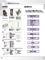
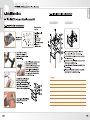
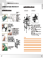
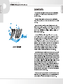
PW 850i CPU Liquid Cooling System
©
©
©
© ©
y И.
В50г
User's Manual
Limited Liability
These warranties replace all other warranties, expressed or implied including,
but not limited to, the implied warranties of merchantability and fitness for a
particular purpose.
Thermaltake disclaims all other warranties, expressed or implied including,
without limitation, implied warranties of merchantability and fitness for a particular
purpose.
Some jurisdictions do not allow the exclusion of implied warranties so this
limitation may not apply to you. All expressed and implied warranties are limited in
duration to the limited warranty period. No warranties apply after that period, some
jurisdiction do not allow limitation on how long an implied warranty lasts, so this
limitation may not apply to you.
Limitations of liability, Thermaltake's responsibility under this, or any other
warranty, implied or expressed, are limited to repair or replacement, as set forth
above. These remedies are the sole and exclusive remedies for any breach of
warranty. Thermaltake is not responsible for direct, special, incidental, or
consequential damages resulting from any breach of warranty or under any other
legal theory including, but not limited to, lost profits, downtime, goodwill, damage
to or replacement of equipment and property, and any cost of recovering,
reprogramming, or reproducing any program or data stored in or used with a
system containing Thermaltake product. Some jurisdictions do not allow the
exclusion or limitation of incidental or exclusions may not apply to you.
Extent of limited warranty, Thermaltake does not warrant that your product will
be free from design defects or errors known as "ERRATA". Current characterized
errata are available upon request. This limited warranty does not cover any costs
relating to removal or replacement of any part that is soldered or otherwise affixed
to your system's motherboard. This limited warranty does not cover damages due
to external causes, including accidental, problems with electrical power, usage not
in accordance with product instructions, misuse, neglect, alteration, repair,
improper installation, or improper testing. Nor is Thermaltake held liable for any
bodily damage that may result during the installation, maintenance, repair, or is
otherwise associated with this product, Thermaltake is free from any legal actions
that may result in death, pain and anguish, or any other form of personal damage
that may occur by purchasing this product.
You, the buyer, agree to this warranty and its term set within its expressed and
implied limited warranty. This limited warranty gives you specific legal rights, and
you may also have other right that varies from jurisdiction to jurisdiction.
PW 850i CPU Liquid Cooling System
Contents
PW850i Specifications ------------------------- 02
=
2 Components nennen 03
3 Installation steps -------------------------------- 04
4 Install Waterblock
4-1 Intel LGA 775 -----------=============-=eeeeeeeee- 05
4-2 Intel P4 L478 ------------------------------------ 07
4-3 AMD K8 ------------==========ccceeeeeeeeeeeeeoeo— 09
4-4 AMD AM2 / AM2+ -----------==--===============—-—- 12
9 Install 12cm Radiator --------------------------- 15
6 Install Pump and Tank -------------------------- 19
7
8
Install Water Tube ------------------------------- 20
Fill coolant -------------------------00000000 000 ess 24
9 Install iStripe ------------------------------------ 26
01
1. Specification
Dimension
Material
Tubing & Hoes Clip
Weight
Water Block
Dimension
Bearing
Maximum Capacity
Rated Voltage
Input current
Connector
Noise
Life time
Dimension
Material
TMG Radiator ME
Fin Design
Tubing & Hoes Clip
Fan Dimension
Fan Speed
Noise
Fan Connector
Dimension
Liquid Tank Capacity
Tubing & Hoes Clip
iStripe Length
Material
Dimension
Flow TX
Tubing & Hoes Clip
Dimension
Tube
Material
Capacity
Coolant
Major Material Ingredient
Application
58mm(L) X 58mm(W) X 35mm(H)
All copper designed
For 9.5mm ID (3/8") tubing
336(g)
75(L) x 70(W) x 75(H) mm
Ceramic bearing
500 L/ hr
DC 12V
600 MA
4 pin
16 dBA
80000 hr (MTBF)
153(L) x 120(W) x 28(H) mm
Aluminum
Aluminum , Dimple
Aluminum , Louvered
For 9.5mm ID (3/8") tubing
120(L) x 120(W) x 25(H) mm
1300 ~ 2400 RPM
16 ~ 30 dB
4 pin
86(L) x 66(W) x 110(H) mm
350c.c
For 9.5mm ID(3/8") tube
300 mm x2pcs
TPU
60mm(H) x 35 mm (W) x 25 mm (D)
For 9.5mm ID(3/8") tube
9.5mm ID(3/8") tube
Green UV
500c.c
Propylene Glycol
AMD AM2/AM2+
AMD K8
Intel LGA775
Intel P4
02
PW 850i CPU Liquid Cooling System
2.Components
3.Installation steps
We strongly suggest the following installation procedures.
12cm TMG Radiator with All copper water block
VR fan (1300~2400RPM) For Intel P4 775/ P4 478
and AMD AM2/ AM2+/K8
© i
® 95mm
3/8"
€
ID 9.5mm(3/8")UV sensitive UV sensitive 500 cc
Flow Tx Water Tube 400cm x 1 Coolant x 1
Bag(A)
Clips for :
- Intel LGA 775 & P4 478
- AMD AM2/AM2+ & K8
A-Metal H-type clip FN
B-Cushion —)
C-Insulator
D-50mm screws x4
ЕР С° E-Thumb nuts x4
= e F-White washers x4
22 G-Thermal compound
“_H-38mm screws x4
| -Stand offs x4
J -Red washers x4
istripe 30cm x 2
M Il K-6mm Screws O SU
for PCI bracket x 2 e O- Screws and nuts
| L-PCI bracket (for pump) X 4
Nue © M-Velcro tt P- Screws
L di o O N-Hose Clips P si (for radiator) X 4
Bw (for tube) x 10
03
Failure to comply may result in leaks and damaged components.
| Components Check
P.03
у
Install Waterblock
- Intel LGA 775 P.05
- Intel P4478 P.07
- AMD K8 P.09
- AMD AM2 / AM2+ P.12
у
| Install 12cm Radiator
у
| Install Pump & Tank
P.19
у
| Install Water tube
P.20
Y
| Fill Coolant
P.24
у
| Install iStripe
P.26
у
| Installation Complete
04
PW 850i CPU Liquid Cooling System
4.Install Waterblock
4-1 Intel LGA 775 - Secure Waterblock onto CPU
4-1.1 Install the Clip on Motherboard
Components for
LGA 775:
| | Fa BE, A-MetalH-typeciip
ado EXE B-Cushion
Intel LGA 775 4 le C-Insulator
Motherboard sE > -50mm screws
D et E-Thumb nuts
\ ® G-Thermal compound
ww J «G |! -Stand offs
q | J J -Red washers
Tear off the tape on the
back of the insulator (C)
and place it on the metal
H-type clip(A).
Note: Placing the cushion onto
the motherboard with the
adhesive will prevent you from
removing the cushion in the
future. If you are planning to
remove the cushion for future
use, please don't remove the
protective tape.
Combine the insulator(C) and
the cushion (B) using the
adhesive. Stick the metal H-type
clip(A) with the insulators (BC).
Tear off the protective layer to
adhere it onto the motherboard.
@ © ©
Attach H-type clips(including
ABC)on the back side of
motherboard.
05
4-1.2 Install Waterblock on Motherboard
Completed View
Exploded View
J
7 3 (ABC) 1.Insert the screws (D) through the clip(ABC)
into the four holes on the Motherboard.
2.Put the washers (J) along the screws to prevent
© the electric current.
3.Put the stand offs (1) along the screws to fix the
screws on the motherboard.
4.Apply a thin layer of thermal compound(G) onto
the processor.
5.Place waterblock on the processor through the
screws and fix it by thumb nuts(E).
06
PW 850i CPU Liquid Cooling System
4-2 Intel P4 Socket 478 - Secure Waterblock onto CPU
4
2.1 Install the Cli
on Motherboar
Components for
Exploded View
4-2.2 Install Waterblock on Motherboard
Completed View
P4 478 :
A NN
Г ( B с A-Metal H-type clip
Á A B-Cushion
E E a C-Insulator
Intel P4 478 a 7 | D-50mm screws
Motherboard a E-Thumb nuts
D G-Thermal compound
we J G | -Stand offs
| I J -Red washers
\_ J
Tear off the tape on the
back of the insulator (C)
and place it on the metal
H-type clip(A).
1.Insert the screws (D) through the clip(ABC)
into the four holes on the Motherboard.
2.Put the washers (J) along the screws to prevent
the electric current.
3.Put the stand offs (1) along the screws to fix the
screws on the motherboard.
4.Apply a thin layer of thermal compound(G) onto
the processor.
5.Place waterblock on the processor through the
screws and fix it by thumb nuts(E).
© ÿ © 906
Note: Placing the cushion onto
the motherboard with the
adhesive will prevent you from
removing the cushion in the
future. If you are planning to
remove the cushion for future
use, please don't remove the
protective tape.
Combine the insulator(C) and .
the cushion (B) using the Note:
adhesive. Stick the metal H-type
clip(A) with the insulators (BC).
Tear off the protective layer to
adhere it onto the motherboard.
© © ©
Attach H-type clips(including
ABC)on the back side of
motherboard.
07
PW 850i CPU Liquid Cooling System
4-3 AMD K8 Socket 754 / 939 / 940 - Secure Waterblock onto CPU
4-3.1 Standard installation - Install waterblock by
motherboard back plate
4-3.1.1 Check The Back Plate
AMD K8 I | Remove the retention
Motherboard 261 frame from motherboard.
G Components for
H AMD Ka8:
\ G-Thermal compound
5 H-38mm screws Check Your Back Plate!
A. Ifthe back plate does have
threaded standoffs, please
continue with standard installation.
B. If the back plate does NOT have
4-3.1.2 Install Waterblock on Motherboard Inreaded standoffs, please continue
Exploded View Completed View
4 N
\ J
1.Apply a thin layer of thermal compound(G)
onto the processor.
2.Place waterblock on the processor.
3.Secure the waterblock on the motherboard by
using screws(H).
09
4-3.2 Install waterblock by clips included in package
4-3.2.1 Install the Clip on Motherhoard
Components for
AMD Ka8:
A-Metal H-type clip
B-Cushion
C-Insulator
D-50mm screws
E-Thumb nuts
F-White washers
G-Thermal compound
AMD K8 Motherboard
J | -Stand offs
Remove the retention
module from the motherboard.
Remove the back plate on
back side of motherboard.
Tear off the tape on the back of
the insulator (C) and place it on
) the metal H-type clip(A).
Note: Placing the cushion onto
the motherboard with the
adhesive will prevent you from
removing the cushion in the
future. If you are planning to
remove the cushion for future
/ use, please don't remove the
protective tape.
10
PW 850i CPU Liquid Cooling System
". MIT art
PU т.
Mi АНТ
МАН
ЗН
Combine the insulator(C) and the
cushion (B) using the adhesive.
Stick the metal H-type clip(A) with the
insulators (BC). Tear off the protective
layer to adhere it onto the motherboard.
Attach H-type clips(including
ABC)on the back side of
motherboard.
4-3.2.2 Install Waterblock on Motherboard
Exploded View
11
Completed View
1.Insert the screws (D) through the clip(ABC)
into the two holes on the Motherboard.
2.Put the washers (F) along the screws to prevent
the electric current.
3.Put the stand offs (1) along the screws to fix the
screws on the motherboard.
4.Apply a thin layer of thermal compound(G) onto
the processor.
5.Place waterblock on the processor through the
screws and fix it by thumb nuts(E).
4-4 AMD Socket AM2/AM2+ - Secure Waterblock onto GPU
4-4.1 Standard installation - Install waterblock hy
motherboard back plate
4-4.1.1 Check The Back Plate
Remove the retention
AMD AM2 frame from motherboard.
Motherboard
y Components for
AMD AM2/AM2+:
G-Thermal
compound
\ H-38mm screws x Check Your Back Plate!
\ J A. If the back plate does have
threaded standoffs, please
continue with standard installation.
B. Ifthe back plate does NOT have
threaded standoffs, please continue
4-4.1.2 Install Waterblock on Motherboard with 4-4.2.
Exploded View Completed View
| 4 = A
1.Apply a thin layer of thermal compound(G)onto
the processor.
2.Place waterblock on the processor.
3.Secure the waterblock on the motherboard
by using screws(H).
12
PW 850i CPU Liquid Cooling System
4-4.2 Install waterblock by clips included in package
4-4.2.1 Install the Clip on Motherboard
AMD AM2 Motherboard Components for AMD AM2/AM2+ :
( à ( | A-Metal H-type clip
B-Cushion
C-Insulator
D-50mm screws
E-Thumb nuts
F-White washers
G-Thermal compound
| -Stand offs
Remove the retention
module from the motherboard.
Remove the back plate on
back side of motherboard.
Tear off the tape on the back of
the insulator (C) and place it on
the metal H-type clip(A).
Note: Placing the cushion onto
the motherboard with the
adhesive will prevent you from
removing the cushion in the
future. If you are planning to
remove the cushion for future
use, please don't remove the
protective tape.
13
E
qu Wu A
МН it Hit
Gt tl,
RTE
An
Exploded View
EA A
Combine the insulator(C) and the
cushion (B) using the adhesive.
Stick the metal H-type clip(A) with the
insulators (BC). Tear off the protective
layer to adhere it onto the motherboard.
Attach H-type clips(including
ABC)on the back side of
motherboard.
4-2.2.2 Install Waterblock on Motherboard
Completed View
the electric current.
3.Put the stand offs (1) along the screws to fix the
screws on the motherboard.
4.Apply a thin layer of thermal compound(G) onto
the processor.
5.Place waterblock on the processor through the
screws and fix it by thumb nuts(E).
J
1.Insert the screws (D) through the clip(ABC)
into the four holes on the motherboard.
2.Put the washers (F) along the screws to prevent
14
15
PW 850i CPU Liquid Cooling System
9. Install 12cm Radiator
Two options for installing the 120mm radiator. Before mounting the 120mm
radiator, please check the dimension of back panel of your case first.
Radiator clearance requirement:
155(L) x 125(W) x 65(H)mm
5-1. Option 1(Inside the case):
If the radiator fits onto your back panel without
any interference, please choose option 1(5-1).
5-2. Option 2(Outside the case):
If there is interference between radiator and
back panel of your case, please choose option 2(5-2).
5-1 Option 1(Inside the case)
Remove the original fan module.
Install and secure Radiator
module by screws(P).
Connect the 4-pin connector
of 12cm fan to power supply.
Connect the yellow wire(RPM signal)
Note:
It is fine to place the radiator
upside down if necessary as
it will not affect its cooling
performance significantly.
to the motherboard's fan connector.
16
PW 850i CPU Liquid Cooling System
5-2 Option 2(Outside the case)
— -
Remove the original fan module.
Unscrew the fan grill and the fan.
Reverse the fan and secure the fan grill
and the fan by original screws.
Note:
Please note the direction of fan
should be as shown.
Install and secure radiator module
by screws(P).
Installation complete.
17
Insert the wire from radiator to
the PCI bracket. Replace the PCI bracket(L)
bundled in the package to one of the
free PCI slots and secure it by screw(K).
Connect the 4-pin connector
of 12cm fan to power supply.
Connect the yellow wire(RPM signal)
to the motherboard's fan connector.
18
PW 850i CPU Liquid Cooling System
6.Install Pump & Tank
If there are mounting holes on the bottom of your case.
Yo
u may p
fit the stand of pump.
to power supply.
Installation complete.
19
roceed with the following steps to install the pump.
Finding the mounting holes to
Insert the screws(O) through the
holes of the stand as shown.
Insert the nuts and tighten
= e Mel them as shown.
Connect the 4-pin connector of pump
Note:
If there are not mounting
holes on your case, find a
location in the case to safely
position the pump and tank
\ With the velcro(M) .
7.Install Water tube
Pure copper
waterblock
12cm TMG Radiator
Flow Tx
Connect Waterblock to Radiator
Remove black rubber
caps from the waterblock.
Insert the hose clip(N) through the tube.
20
PW 850i CPU Liquid Cooling System
Connect the tube with
the waterblock.
Use pliers to tighten the hose clip(N).
Insert the hose clip(N) through the tube.
Connect the tube with the radiator from
waterblock.
Use pliers to tighten the hose clip(N).
\
4
ES
ГЛ
|
— UN
= ve: NH
Insert the hose clip(N) through a tube.
Connect the tube with the radiator.
Use pliers to tighten the hose clip(N).
21
Insert the hose clip(N) through the tube.
Connect the tube with the Flow TX from
radiator.
Use pliers to tighten the hose clip(N).
Connect Flow Tx to Tank
Qu ZO. =
| SAS 4
| =X, / CA |
ATP
Insert the hose clip(N) through a tube.
Connect the tube with the Flow TX.
Use pliers to tighten the hose clip(N).
Insert the hose clip(N) through the tube.
Connect the tube with the tank from
Flow TX.
Use pliers to tighten the hose clip(N).
22
PW 850i CPU Liquid Cooling System
8. Fill Coolant
Connect Pump to Waterblock
Open the cover of Fill the tank up with coolant. Turn on the PC power switch.
liquid tank.
Insert the hose clip(N) through a tube. 4
Connect the tube with the pump.
Use pliers to tighten the hose clip(N).
Liquid level will decrease when you
power on the system, please keep filling
coolant until the tank is filled up.
Please make sure liquid is
flowing continuously and
smoothly within the tube.
Insert the hose clip(N) through the tube.
Connect the tube with the waterblock
from pump.
Use pliers to tighten the hose clip(N).
Installation complete.
Close the cover
of liquid tank. Adjust the fan speed. Turn off the PC power switch.
23 24
PW 850i CPU Liquid Cooling System
9. Install iStripe
First determine the length
required for iStripe.
Then cut the iStripe
accordingly.
Installation complete
Entwine the iStripe
around the UV tube in
the same direction
Installation complete
Note:
1. If bubbles are forming within the tubing, you may tap the
tubing gently to remove them until all are gone.
2. After installation is completed, please ensure there are no
"WE ERE
bent tubings.
25 26
PW 850i CPU Liquid Cooling System
10. Uninstall The System
27
Loosen the nuts of pump.
Remove pump and tank from case.
Take the pump and tank apart to dispose
the coolant to a container.
Please wipe the coolant
on the pump and tank,
especially the connection
Note: Please refer to previous installation instructions
regarding the uninstallation procedures for other components.
between the pump and tank.
11.0 &A
Q: How often do I have to refill the system?
A:
Depending on the usage or surrounding environment,
we strongly recommend checking the water level
once a month to ensure optimal performance.
If the liquid level is below the low level, please follow
the installation steps(P.24) to refill the coolant.
: How do I uninstall the liquid cooling system?
- There are no special instruction when un-installing.
Please refer to installation and reverse the procedures.
: Can | add another liquid cooling upgrade kits on my
liquid cooling system?
- Yes, there are numerous upgrades available for all
different components in PC.
Please visit www.thermaltake.com for more information.
: How do I know if the pump is working?
: Place your hand on the pump.
If the pump is operating, the pump should vibrate gently.
: I'm running low on coolant. What's happening and
what can | do?
: The Performance Coolant included with PW 850i
contains water based material so it is subject to natural evaporation.
It is normal for the coolant to decrease depending on the usage or
surrounding environment. For best performance, we highly
recommend replacing the coolant every 6 month.
28