1
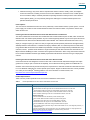
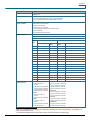
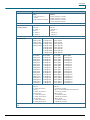
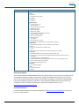
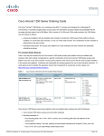
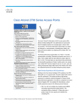
.
Data Sheet
Cisco Aironet 1250 Series Access Point
Performance with Investment Protection
● Up to nine times faster than 802.11a/g
networks
● Backward-compatible with 802.11a/b/g clients
● M-Drive technology optimizes RF
Flexible Platform
● Versatile RF coverage with external antennas
● Supports both 2.4-GHZ and 5-GHz modules
®
®
The Cisco Aironet 1250 Series is a rugged indoor access point
designed for challenging RF environments that require the antenna
versatility associated with connectorized antennas, a rugged metal
enclosure, and a broad operating temperature range. The first
enterprise-class access point to support the IEEE 802.11n draft 2.0
standard, it offers combined data rates of up to 600 Mbps to
provide users with mobile access to high-bandwidth data, voice,
and video applications. 802.11n provides reliable and predictable
WLAN coverage to improve the end-user experience for both
existing 802.11a/b/g clients and new 802.11n clients.
As part of the Cisco Unified Wireless Network, the 1250 Series provides
the industry’s lowest total cost of ownership and investment protection by
integrating seamlessly with the existing network. With a Gigabit Ethernet
Rugged Metal Housing and Extended
Operating Temperature
● Ideal for factories, warehouses, and other
industrial environments
● UL 2043 plenum rated for above ceiling
installation options or suspended from drop
ceilings
Secure Interoperability
● 802.11n draft 2.0 compliant
● Intel Connect with Centrino Certified
Simplified Network Management
● Controller-based or standalone deployment
options
● CleanAir* technology reduces troubleshooting
and performance impacts
Secure Connections
● Supports rogue access point detection and
denial of service attacks
● Management frame protection detects
malicious users and alerts network
administrators
Greater Network Capacity
● Dynamic frequency selection 2 (DFS-2)
compliant
(10/100/1000) interface, the Cisco Aironet 1250 Series offers the flexibility
of inline as well as local power options.
RF Excellence
The Cisco Unified Wireless Network with M-Drive technology removes the mystery associated with design,
implementation, and ongoing optimization of enterprise wireless networks. With Cisco M-Drive technology, IT has
the tools needed to build and operate a high-performance wireless network without the need for extensive RF
engineering skills. Cisco M-Drive technology is a systemwide approach that manages the corporate RF spectrum,
improves wireless coverage, and increases system capacity and performance. Features include:
●
Radio resource management (RRM): Automated self-healing optimizes RF to reduce unpredictability and
dead spots and to help ensure high-availability client connections. RRM optimizes network capacity and
mitigates interference by continuously monitoring and adjusting access point power and channel settings and
then load balancing clients to enhance wireless coverage.
© 2009 Cisco Systems, Inc. All rights reserved. This document is Cisco Public Information.
Page 1 of 8
Data Sheet
●
CleanAir technology: Only Cisco offers a comprehensive solution to detect, classify, locate, and mitigate
sources of interference, including non-Wi-Fi sources such as Bluetooth, microwave ovens, cordless phones,
and more. With the ability to visualize performance-impacting interference directly from the Cisco Wireless
Control System (WCS), you can proactively manage the challenges of a shared wireless spectrum and
optimize network performance.
Power Options
The Cisco Aironet 1250 Series Access Point can be powered by a Cisco Ethernet switch, a power injector, or a local
power supply. The number of radio modules determines which Cisco Ethernet switch can power the Aironet 1250
Series Access Point.
Powering the Aironet 1250 Series Access Point with 802.3af Power over Ethernet
The Aironet 1250 Series Access Point with one RM1252 radio module installed requires 12.95W, which is within the
802.3af Power over Ethernet (PoE) standard. Any Cisco switch supporting 802.3af may be used to power the Aironet
1250 Series Access Point with one RM1252 radio module installed. This is ideal for businesses that chose to only
deploy on a single frequency (2.4 GHz or 5 GHz). A single radio provides optimum performance with approximately
300 Mbps maximum PHY data rate. Customers who deploy dual-band, 802.11n radios and power the 1250 Series
using standard 802.3af will have more reliable and predictable coverage than that provided by traditional 802.11a/g
networks; however, operation will be limited to a single transmitter per radio with maximum PHY data rates of 150
Mbps instead of 300 Mbps per radio. Customers with a significant investment in 802.11 a/b/g client devices that have
low-to-medium bandwidth needs but high-reliability requirements will benefit the most from this type of deployment
scenario.
Powering the Aironet 1250 Series Access Point with Cisco Enhanced PoE
Cisco Enhanced PoE was designed for customers who want to install new PoE-enabled technologies that require
greater than 15.4W per port to function at full capability, such as wireless technology based on the IEEE 802.11n
standard. Cisco Enhanced PoE provides the full power requirements for dual-radio modules and eliminates the need
to run an additional cabling drop or insert a separate power injector. Support for Enhanced PoE is currently available
®
on a variety of Cisco Catalyst switching platforms. For more information on Enhanced PoE, visit
http://www.cisco.com/en/US/prod/switches/epoe.html.
Product Specifications
Table 1 lists the product specifications for Cisco Aironet 1250 Series Access Points.
Table 1.
Product Specifications for Cisco Aironet 1250 Series Access Points
Item
Specification
Part Numbers
Access point platform with pre-installed radio modules:
● AIR-AP1252AG-x-K9 802.11a/g/n-draft 2.0 2.4/5-GHz Modular Autonomous AP; 6 RP-TNC
● AIR-AP1252G-x-K9 802.11g/n-draft 2.0 2.4-GHz Modular Autonomous AP; 3 RP-TNC
● AIR-LAP1252AG-x-K9 802.11a/g/n-draft 2.0 2.4/5-GHz Modular Unified AP; 6 RP-TNC
● AIR-LAP1252G-x-K9 802.11g/n-draft 2.0 2.4-GHz Modular Unified AP; 3 RP-TNC
Individual components:
● AIR-AP1250= Modular Auto AP Platform (no radio modules); Spare
● AIR-LAP1250= Modular Unified AP Platform (no radio modules); Spare
● AIR-RM1252A-x-K9= 802.11a/n-d2.0 5-GHz Radio Module; 3 RP-TNC
● AIR-RM1252G-x-K9= 802.11g/n-d2.0 2.4-GHz Radio Module; 3 RP-TNC
● AIR-AP1250MNTGKIT= 1250 Series Ceiling, Wall Mount Bracket kit- Spare
● AIR-LAP1252-x-K9-5 Eco-pack 802.11a/g/n 2.4/5 GHz Mod Unified AP, FCC, 5 APs Regulatory domains: (x =
regulatory domain)
Customers are responsible for verifying approval for use in their individual countries. To verify approval and to
identify the regulatory domain that corresponds to a particular country, please visit
http://www.cisco.com/go/aironet/compliance.
© 2009 Cisco Systems, Inc. All rights reserved. This document is Cisco Public Information.
Page 2 of 7
Data Sheet
Item
Specification
Not all regulatory domains have been approved. As they are approved, the part numbers will be available on the
Global Price List.
®
Software
● Cisco IOS Software Release 12.4(10b)JA or later (Autonomous Mode).
● Cisco IOS Software Release 12.4(10b)JX or later (Unified Mode).
● Cisco Unified Wireless Network Software Release 4.2 or later.
Draft 802.11n Version 2.0 (and
Related) Capabilities
● 2x3 MIMO with two spatial streams
● Maximal Ratio Combining (MRC)
● 20-and 40-MHz channels
● PHY data rates up to 300 Mbps
● Packet aggregation: A-MPDU (Tx/Rx), A-MSDU (Tx/Rx)
● 802.11 DFS (Bin 5)
● Cyclic Shift Diversity (CSD) support
Data Rates Supported
802.11a: 6, 9, 12, 18, 24, 36, 48, and 54 Mbps
802.11g: 1, 2, 5.5, 6, 9, 11, 12, 18, 24, 36, 48, and 54 Mbps
802.11n data rates (2.4 GHz and 5 GHz):
MCS
Index1
Frequency Band and 20-MHz
Operating Channels
2
GI = 800ns
GI = 400ns
20-MHz Rate (Mbps)
40-MHz Rate
(Mbps)
20-MHz Rate
(Mbps)
40-MHz Rate (Mbps)
0
6.5
13.5
7.2
15
1
13
27
14.4
30
2
19.5
40.5
21.7
45
3
26
54
28.9
60
4
39
81
43.3
90
5
52
108
57.8
120
6
58.5
121.5
65
135
7
65
135
72.2
150
8
13
27
14.4
30
9
26
54
28.9
60
10
39
81
43.3
90
11
52
108
57.8
120
12
78
162
86.7
180
13
104
216
115.6
240
14
117
243
130
270
15
130
270
144.4
300
-A (Americas (FCC)):
● 2.412 to 2.462 GHz; 11
channels
● 5.180 to 5.320 GHz; 8 channels
● 5.500 to 5.700 GHz, 8 channels
(excludes 5.600 to 5.640 GHz)
● 5.745 to 5.825 GHz; 5 channels
-C (China):
● 2.412 to 2.472 GHz; 13
channels
● 5.745 to 5.825 GHz; 5 channels
-E (ETSI):
● 2.412 to 2.472 GHz; 13
channels
● 5.180 to 5.320 GHz; 8 channels
● 5.500 to 5.700 GHz, 11
-K (Korea):
● 2.412 to 2.472 GHz; 13 channels
● 5.180 to 5.320 GHz; 8 channels
● 5.500 to 5.620 GHz, 7 channels
● 5.745 to 5.805 GHz, 4 channels
-N (Non-FCC):
● 2.412 to 2.462 GHz; 11 channels
● 5.180 to 5.320 GHz; 8 channels
● 5.745 to 5.825 GHz; 5 channels
-P (Japan2):
● 2.412 to 2.472 GHz; 13 channels
● 5.180 to 5.320 GHz; 8 channels
-S (Singapore):
● 2.412 to 2.472 GHz; 13 channels
● 5.180 to 5.320 GHz; 8 channels
1
MCS Index: The Modulation and Coding Scheme (MCS) index determines the number of spatial streams, the modulation, the
coding rate, and data rate values.
GI: A Guard Interval (GI) between symbols helps receivers overcome the effects of multipath delays.
2
© 2009 Cisco Systems, Inc. All rights reserved. This document is Cisco Public Information.
Page 3 of 7
Data Sheet
Item
Specification
● 5.745 to 5.825 GHz; 5 channels
channels
-I (Israel):
● 2.412 to 2.472 GHz, 13
channels
● 5.180 to 5.320 GHz; 8 channels
-T (Taiwan):
● 2.412 to 2.462 GHz; 11 channels
● 5.280 to 5.320 GHz; 3 channels
● 5.500 to 5.700 GHz, 11 channels
● 5.745 to 5.825 GHz; 5 channels
Note: This varies by regulatory domain. Refer to the product documentation for specific details for each regulatory domain.
Maximum Number of NonOverlapping Channels
2.4 GHz
● 802.11b/g:
5 GHz
● 802.11a:
◦ 20 MHz: 3
● 802.11n:
◦ 20 MHz: 21
● 802.11n:
◦
20 MHz: 3
◦
20 MHz: 21
◦
40 MHz: 1
◦
40 MHz: 9
Note: This varies by regulatory domain. Refer to the product documentation for specific details for each regulatory domain.
Receive Sensitivity
Maximum Transmit Power
802.11b
802.11g
802.11a
–90 dBm @ 1 Mb/s
–87 dBm @ 6 Mb/s
–86 dBm @ 6 Mb/s
–89 dBm @ 2 Mb/s
–86 dBm @ 9 Mb/s
–85 dBm @ 9 Mb/s
–87 dBm @ 5.5 Mb/s –83 dBm @ 12 Mb/s
–82 dBm @ 12 Mb/s
–85 dBm @ 11 Mb/s
–82 dBm @ 18 Mb/s
–81 dBm @ 18 Mb/s
–81 dBm @ 24 Mb/s
–80 dBm @ 24 Mb/s
–80 dBm @ 36 Mb/s
–79 dBm @ 36 Mb/s
–75 dBm @ 48 Mb/s
–74 dBm @ 48 Mb/s
–74 dBm @ 54 Mb/s
–73 dBm @ 54 Mb/s
2.4-GHz
2.4-GHz
5-GHz
802.11n (HT20)
802.11n (HT40)
802.11n (HT20)
802.11n (HT40)
–86 dBm @ MC0
–86 dBm @ MC0
–85 dBm @ MC0
–85 dBm @ MC0
–85 dBm @ MC1
–85 dBm @ MC1
–84 dBm @ MC1
–84 dBm @ MC1
–84 dBm @ MC2
–84 dBm @ MC2
–83 dBm @ MC2
–83 dBm @ MC2
–83 dBm @ MC3
–80 dBm @ MC3
–82 dBm @ MC3
–79 dBm @ MC3
–80 dBm @ MC4
–77 dBm @ MC4
–79 dBm @ MC4
–76 dBm @ MC4
–75 dBm @ MC5
–72 dBm @ MC5
–74 dBm @ MC5
–71 dBm @ MC5
–74 dBm @ MC6
–71 dBm @ MC6
–73 dBm @ MC6
–70 dBm @ MC6
–73 dBm @ MC7
–70 dBm @ MC7
–72 dBm @ MC7
–69 dBm @ MC7
–86 dBm @ MC8
–86 dBm @ MC8
–85 dBm @ MC8
–85 dBm @ MC8
–85 dBm @ MC9
–85 dBm @ MC9
–84 dBm @ MC9
–84 dBm @ MC9
–84 dBm @ MC10
–84 dBm @ MC10
–83 dBm @ MC10
–83 dBm @ MC10
–83 dBm @ MC11
–80 dBm @ MC11
–82 dBm @ MC11
–79 dBm @ MC11
–80 dBm @ MC12
–77 dBm @ MC12
–79 dBm @ MC12
–76 dBm @ MC12
–75 dBm @ MC13
–72 dBm @ MC13
–74 dBm @ MC13
–71 dBm @ MC13
–74 dBm @ MC14
–71 dBm @ MC14
–73 dBm @ MC14
–70 dBm @ MC14
–73 dBm @ MC15
–70 dBm @ MC15
–72 dBm @ MC15
–69 dBm @ MC15
2.4GHz
● 802.11b
5-GHz
5GHz
● 802.11a
◦ 23 dBm with 1 antenna
● 802.11g
◦ 17 dBm with 1 antenna
● 802.11n non-HT duplicate (802.11a duplicate) mode
◦ 20 dBm with 1 antenna
● 802.11n (HT20)
◦ 17 dBm with 1 antenna
● 802.11n (HT20)
◦
17 dBm with 1 antenna
◦
◦
20 dBm with 2 antennas
◦
● 802.11n (HT40)
17 dBm with 1 antenna
20 dBm with 2 antennas
● 802.11n (HT40)
◦
17 dBm with 1 antenna
◦
17 dBm with 1 antenna
◦
20 dBm with 2 antennas
◦
20 dBm with 2 antennas
Note: The maximum power setting will vary by channel and according to individual country regulations. Refer to the product documentation for specific
details.
© 2009 Cisco Systems, Inc. All rights reserved. This document is Cisco Public Information.
Page 4 of 7
Data Sheet
Item
Specification
Available Transmit Power
Settings
2.4GHz
5GHz
23 dBm (200 mW)
20 dBm (100 mW)
20 dBm (100 mW)
17 dBm (50 mW)
17 dBm (50 mW)
14 dBm (25 mW)
14 dBm (25 mW)
11 dBm (12.5 mW)
11 dBm (12.5 mW)
8 dBm (6.25 mW)
8 dBm (6.25 mW)
5 dBm (3.13 mW)
5 dBm (3.13 mW)
2 dBm (1.56 mW)
2 dBm (1.56 mW)
–1 dBm (0.78 mW)
–1 dBm (0.78 mW)
Note: The maximum power setting will vary by channel and according to individual country regulations. Refer to the product documentation for specific
details.
Antenna Connectors
● 2.4-GHz: 3 RP-TNC connectors
● 5-GHz: 3 RP-TNC connectors
Interfaces
● 10/100/1000BASE-T autosensing (RJ-45)
● Management console port (RJ45)
Indicators
● Status LED indicates operating state, association status, error/warning condition, boot sequence, and
maintenance status.
● Ethernet LED indicates activity over the Ethernet, status.
Modularity
● Number of radio module slots: 2
● Available radio modules
● Radio LED indicates activity over the radio, status.
Part Number
Description
Maximum per AP1250 platform
AIR-RM1252A-x-K9
2.4 802.11a/n-d2.0 5-GHz Radio Module; 3
RP-TNC
1
AIR-RM1252G-x-K9
802.11g/n-d2.0 2.4-GHz Radio Module; 3 RPTNC
1
Dimensions (W x L x H)
● AP (without mounting bracket): 8.12 x 9.52 x 2.35 in. (20.62 x 24.18 x 5.97 cm)
● AP (with mounting bracket): 8.12 x 9.52 x 2.75 in. (20.62 x 24.18 x 6.99 cm)
Weight
● AP with 2 radios installed: 5.1 lbs (2.31 kg)
● AP chassis: 2.1 lbs (0.95 kg)
● 2.4 GHz radio: 1.5 lbs (0.68 kg)
● 5 GHz radio: 1.5 lbs (0.68 kg)
Environmental
Nonoperating (storage) temperature: –40 to 185°F (–40 to 85°C)
Operating temperature: –4 to +131°F (–20 to +55°C)
Operating humidity: 10 to 90 percent (noncondensing)
System Memory
● 64 MB DRAM
● 32 MB flash
Input Power Requirements
● AP1250: 36 to 57 VDC
● Power Supply and Power Injector: 100 to 240 VAC; 50 to 60 Hz
Powering Options
● Cisco Catalyst switch port capable of sourcing 20W or greater
● Cisco AP1250 Power Injector (AIR-PWRINJ4)
● Cisco AP1250 Local Power Supply (AIR-PWR-SPLY1)
● 802.3af switch (AP1250 with single radio only)
Power Draw
● AP1250 with two RM1252 radio modules installed: 18.5W
● AP1250 with one RM1252 radio module installed: 12.95W
Note: For a 1250 Series Access Point with two radios, 18.5W is the maximum power required at the access point
(powered device). When deployed using PoE, the power drawn from the power sourcing equipment will be higher
by some amount dependent on the length of the interconnecting cable. This additional power may be as high as
1.5W, bringing the total system power draw (access point + cabling) to 20W. A similar consideration applies for a
1250 Series Access Point with one radio.
Warranty
90 days
© 2009 Cisco Systems, Inc. All rights reserved. This document is Cisco Public Information.
Page 5 of 7
Data Sheet
Item
Specification
Compliance
Standards
● Safety:
◦
UL 60950-1
◦
CAN/CSA-C22.2 No. 60950-1
◦
UL 2043
◦
IEC 60950-1
◦
EN 60950-1
● Radio approvals:
◦
FCC Part 15.247, 15.407
◦
RSS-210 (Canada)
◦
EN 300.328, EN 301.893 (Europe)
◦
ARIB-STD 33 (Japan)
◦
ARIB-STD 66 (Japan)
◦
ARIB-STD T71 (Japan)
◦
AS/NZS 4268.2003 (Australia and New Zealand)
◦
EMI and susceptibility (Class B)
◦
FCC Part 15.107 and 15.109
◦
ICES-003 (Canada)
◦
VCCI (Japan)
◦
EN 301.489-1 and -17 (Europe)
◦
EN 60601-1-2 EMC requirements for the Medical Directive 93/42/EEC
● IEEE Standard
◦ IEEE 802.11a/b/g, IEEE 802.11n draft 2.0, IEEE 802.11h, IEEE 802.11d
● Security:
◦
802.11i, Wi-Fi Protected Access 2 (WPA2), WPA
◦
802.1X
◦
Advanced Encryption Standards (AES), Temporal Key Integrity Protocol (TKIP)
● EAP Type(s):
◦
Extensible Authentication Protocol-Transport Layer Security (EAP-TLS)
◦
EAP-Tunneled TLS (TTLS) or Microsoft Challenge Handshake Authentication Protocol Version 2
(MSCHAPv2)
◦
Protected EAP (PEAP) v0 or EAP-MSCHAPv2
◦
Extensible Authentication Protocol-Flexible Authentication via Secure Tunneling (EAP-FAST)
◦
PEAPv1 or EAP-Generic Token Card (GTC)
◦
EAP-Subscriber Identity Module (SIM)
● Multimedia:
◦ Wi-Fi Multimedia (WMM™)
● Other:
◦
FCC Bulletin OET-65C
◦
RSS-102
Service and Support
Cisco and Cisco Wireless LAN Specialized Partners offer a broad portfolio of end-to-end services based on proven
methodologies for planning, designing, implementing, operating, and optimizing the performance of a variety of
secure voice and data wireless network solutions, technologies, and strategies. Cisco Wireless LAN Specialized
Partners bring application expertise to help deliver a secure enterprise mobility solution with a low total cost of
ownership. For more information about Cisco 802.11n planning and deployment services, visit
http://www.cisco.com/go/wirelesslanservices.
For More Information
For more information about the Cisco Aironet 1250 Series, visit http://www.cisco.com/go/wireless or contact your
local account representative.
© 2009 Cisco Systems, Inc. All rights reserved. This document is Cisco Public Information.
Page 6 of 7
Data Sheet
Printed in USA
© 2009 Cisco Systems, Inc. All rights reserved. This document is Cisco Public Information.
C78-423375-05
05/09
Page 7 of 7