1
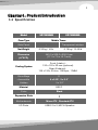
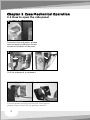
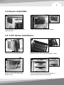
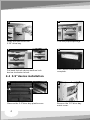
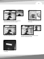
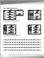
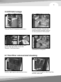
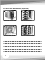
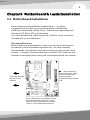
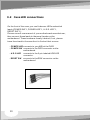
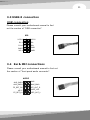
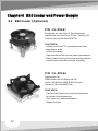
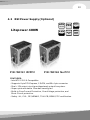
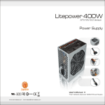
All other registered trademarks belong to their respective companies.
C
2007 Thermaltake Technology Co.,Ltd. All Rights Reserved. www.thermaltake.com
VG7000 Series
User's Manual
Contens
Chapter 1. Product Introduction
1.1 Specification
1
Chapter 2 Case Mechanical Operation
2.1 How to open the side panel
2.2 How to install PSU
2.3 5.25" device installation
2.4 3.5" device installation
2.5 HDD installation
2.6 PCI slot usage
2.7 Fan filter removal and cleaning
2.8 Front Fan Installation (Optional)
2
3
3
4
6
7
7
8
Chapter 3 Motherboard & Leads Installation
3.1 Motherboard Installation
3.2 Case LED connections
3.3 USB2.0 connection
3.4 Ear & MIC connections
9
10
11
11
Chapter 4 RSI Cooler and Power Supply
4.1 RSI Cooler (Optional)
4.2 RSI Power Supply (Optional)
0
12
13
1
Chapter1. Product Introduction
1.1 Specification
Model
VG7000BNS
Case Type
VG7000BWS
Middle Tower
Side Panel
-
Transparent window
Net Weight
6.35 kg / 14 lb
6.19 kg / 13.65 lb
Dimension
(H*W*D)
Cooling System
Drive Bays
- Accessible
- Hidden
440.0 x 200.0 x 500.0 mm
(17.3 x 7.9 x 19.7 inch)
Front (Intake) :
120 x 120 x 25 mm (optional)
Rear (Exhaust) :
120 x 120 x 25 mm, 1300rpm, 17dBA
11
4 x 5.25",
5.25 , 2 x 3.5"
3.5
5 x 3.5"
Material
SECC
Color
Black
Expansion Slots
7
Motherboards
Micro ATX , Standard ATX
I/O Ports
USB 2.0 x 2, MIC & Speaker
Chapter 2 Case Mechanical Operation
2.1 How to open the side panel
1
To remove the side panel, please
remove upper and bottom thumb
screws on the back of the case.
2
Pull the side panel to release it.
Important Notice:
If the air guide interferes with CPU cooling fan,
please remove the CPU air guide as shown.
2
3
2.2 How to install PSU
1
Place power supply unit in the
right position.
2
Then, secure it by screws as shown.
2.3 5.25" device installation
1
Remove the front door first.
2
Remove the 5.25" drive bay
metal cover.
2
Remove the 5.25" drive bay plastic cover.
2
Turn lock device counter-clockwise to
unlock and remove lock device.
4
3
Insert the device into the
5.25" drive bay.
Find the proper openings.
6
5
Put back the lock device and turn lock
device clockwise to lock.
5.25" device installation
complete.
2.4 3.5" device installation
1
2
Remove the 3.5" drive bay plastic cover.
4
Remove the 3.5" drive bay
metal cover.
5
3
4
Turn lock device counter-clockwise to
unlock and remove lock device.
Insert the device into the 3.5"
drive bay.
5
6
Find the proper openings.
Put back the lock device and turn lock
device clockwise to lock.
7
3.5" device installation
complete.
2.5 HDD installation
2
1
Turn lock device counter-clockwise to
unlock and remove lock device.
3
Place HDD into the drive bay.
4
Put back the lock device and turn lock
device clockwise to secure the HDD.
6
HDD installation complete.
7
2.6 PCI slot usage
1
2
Take off the PCI bracket as shown.
3
Locate Graphic Card to the
motherboard through fixing it
on the space of PCI bracket.
4
inner side
Press the inner side of the clip and
pull to the right side to lock the
Graphic Card as shown.
Installation complete.
2.7 Fan filter removal and cleaning
1
Firstly, open up the whole front door.
2
Take off the fan grille, then the filter
can be removed.
2.8 Front Fan Installation (Optional)
2
1
Remove the front door first.
3
Place the fan as shown.
4
Secure the fan by screws.
8
Front fan installation complete.
9
Chapter3 Motherboard & Leads Installation
3.1 Motherboard Installation
Each motherboard has different standoff layout. It is highly
suggested that you refer to your motherboard's manual when
installing motherboard into the Case. The cases are applicable with
Standard ATX, Micro ATX motherboards.
Your motherboard may require a special I/O Panel, which should be
included with your motherboard.
Placement Direction:
When installing the motherboard, make sure you follow the direction
provided by your motherboard manufacturer. On most standard
motherboards, the edge with external ports goes to the rear part of the
chassis. It is highly recommended that you install CPU, heat sink and
modular components before fixing the motherboard inside the chassis.
= the locations of
the screw holes. Note
these locations and
place included
standoffs on the chassis
first.
This side towards
the rear of the
chassis
Above illustration is a sample of what
the motherboard's layout. For more
detail screw hole placement, please
refer to your motherboard manual.
3.2 Case LED connections
On the front of the case, you can find some LEDs and switch
leads (POWER SW*1, POWER LED*1, H.D.D. LED*1,
RESET SW*1 ).
Please consult user manual of your motherboard manufacturer,
then connect these leads to the panel header on the
motherboard. These leads are usually labeled; if not, please
trace them back to the case front to find out their source.
- POWER LED connects to your M/B at the PLED
- POWER SW connects to the PWR connector on the
motherboard.
- H.D.D LED connects to the 2-pin labeled HDD LED
connector.
- RESET SW connects to the RSW connector on the
motherboard.
10
11
3.3 USB2.0 connection
USB connection
Please consult your motherboard manual to find
out the section of "USB connection".
USB
D1-3
4D2-
D1+5
6D2+
GND7
8GND
NC 9
10KEY
USB
2VCC2
VCC11
3.4 Ear & MIC connections
Please consult your motherboard manual to find out
the section of "front panel audio connector".
AUDIO
AUD_GND3
4MIC_BIAS
FP_RET_R5
6FP_OUT_R
KEY7
FP_RET_L9
8AUD_VCC
10FP_OUT_L
IO
2MIC
AUD
AUD_GND1
Chapter4 RSI Cooler and Power Supply
4.1 RSI Cooler (Optional)
P/N : CL-P0441
Designed for Intel Core 2 Duo Processor
Application for Intel Core 2 Duo / Pentium D /
Celeron series (Socket LGA775)
FEATURES:
- Aluminum Crotch Fin provides more heat
dissipation area.
- Silent operation.
Optimized solution for low power processors.
- Back plate & Spring Screw mounting method
ensure safe installation when shipping.
P/N : CL-P0444
Application for
AMD Athlon 64 X2/Athlon 64 FX/
Athlon 64(Socket AM2/ 939/754) and
Sempron (Socket AM2/754)
FEATURES :
- Perfect ratio aluminum extrusion heatsink
for better heat dissipation.
- Tool-less clip, easy installation.
- Silent Solution
12
13
4.2 RSI Power Supply (Optional)
ATX
Litepower 400W
P/N: W0161 W/PFC
PCI
PFC
Express
S-ATA
Universal
AMD/
Intel
X2
Pin
12V 2.0
24(20)
P/N: W0162 No PFC
FEATURES:
- Intel ATX 12V 2.0 Compatible.
- Supports 6-pin PCI-Express, 2 SATA, and 20+4 pin connector.
- Dual +12V output circuit provides steady output for system.
- Super quiet and stable 12cm ball bearing fan.
- Build-in Over Current Protection, Over Voltage protection, and
Short-Circuit protection.
- Safety : UL, CUL, CE, NEMKO, TUV+CB, BSMI, FCC certification.
X1
Dual Core
Support