1
USER’S
GUIDE
Integrated RAID for SAS
April 2007
Version 1.1
®
DB15-000357-01
Proprietary Rights Notice
This document contains proprietary information of LSI Logic Corporation. The
information contained herein is not to be used by or disclosed to third parties
without the express written permission of an officer of LSI Logic Corporation.
Document Description
Document DB15-000357-01, Version 1.1 (April 2007)
This document describes LSI Logic Corporation’s Integrated RAID (IR) software
product and will remain the official reference source for all revisions/releases of
this product until rescinded by an update.
Disclaimer
It is the policy of LSI Logic Corporation to improve products as new technology,
components, software, and firmware become available. LSI Logic reserves the
right to make changes to any products herein at any time without notice. All
features, functions, and operations described herein may not be marketed by LSI
Logic in all parts of the world. In some instances, photographs and figures are
of equipment prototypes. Therefore, before using this document, consult your LSI
Logic representative for information that is applicable and current. LSI LOGIC
DOES NOT ASSUME ANY RESPONSIBILITY OR LIABILITY FOR THE USE OF
ANY PRODUCTS DESCRIBED HEREIN EXCEPT AS EXPRESSLY AGREED
TO IN WRITING BY LSI LOGIC.
LSI Logic products are not intended for use in life-support appliances, devices,
or systems. Use of any LSI Logic product in such applications without written
consent of the appropriate LSI Logic officer is prohibited.
License Restriction
The purchase or use of an LSI Logic Corporation product does not convey a
license under any patent, copyright, trademark, or other intellectual property right
of LSI Logic or third parties.
ii
Version 1.1
Copyright © 2006, 2007 by LSI Logic Corporation. All rights reserved.
Copyright Notice
Copyright © 2006, 2007 by LSI Logic Corporation. All rights reserved.
Trademark Acknowledgments
LSI Logic, the LSI Logic logo design, Fusion-MPT, Integrated Mirroring, and
Integrated Striping are trademarks or registered trademarks of LSI Logic
Corporation. Windows and Windows NT are registered trademarks of Microsoft
Corporation. All other brand and product names may be trademarks of their
respective companies.
KL
For a current list of our distributors, sales offices, and design resource
centers, view our web page located at
http://www.lsi.com
iii
Version 1.1
Copyright © 2006, 2007 by LSI Logic Corporation. All rights reserved.
iv
Version 1.1
Copyright © 2006, 2007 by LSI Logic Corporation. All rights reserved.
Preface
This user’s guide explains how to configure and use the components of
the LSI Integrated RAID (IR) software product with LSI SAS controllers.
Audience
This user’s guide assumes that you have some familiarity with installing
and configuring software programs and that you are familiar with
computer storage devices in general. The people who benefit from this
document are:
•
VARs and OEMs who are evaluating the LSI IR software components
or who are using the IR software product in their computer systems
•
End users who are using the IR software product to configure
mirrored or striped volumes on LSI SAS controllers.
Organization
This document has the following chapters and appendixes:
•
Chapter 1, Introduction to Integrated RAID, provides an overview
of Integrated RAID for SAS controllers, its features, and its benefits.
•
Chapter 2, Overview of Integrated Mirroring and Integrated
Mirroring Enhanced, provides an overview of the LSI Integrated
Mirroring™ (IM) and Integrated Mirroring Enhanced (IME) features.
•
Chapter 3, Creating IM and IME Volumes, describes how to
configure IM and IME volumes with the BIOS-based configuration
utility.
Integrated RAID for SAS User’s Guide
Version 1.1
Copyright © 2006, 2007 by LSI Logic Corporation. All rights reserved.
v
•
Chapter 4, Overview of Integrated Striping, provides an overview
of the LSI Integrated Striping™ (IS) feature.
•
Chapter 5, Creating Integrated Striping Volumes, describes how to
configure Integrated Striping (IS) volumes with the BIOS-based
configuration utility.
•
Appendix A, Using the CFGGEN IR Configuration Utility,
describes how to create IM, IME, and IS volumes using the CFGGEN
IR configuration utility (for manufacturing use only).
Conventions Used in This Manual
The first time a word or phrase is defined in this manual, it is italicized.
Hexadecimal numbers are indicated by the prefix “0x” —for example,
0x32CF. Binary numbers are indicated by the prefix “0b” —for example,
0b0011.0010.1100.1111.
Revision History
Document Number Version/Date
Remarks
DB15-000357-01
Version 1.1
April 2007
Documented the following updated Integrated RAID support:
• Support for up to two volumes consisting of up to twelve
drives per controller, plus one or two hot spare drives. In all,
a maximum of 14 drives per controller.
• IM, IME, and IS volumes support up to ten drives.
• IM and IME arrays support one or two hot spares.
Deleted references to SCSI controllers from Appendix A.
Made many low-level editing improvements.
DB15-000357-00
Version 1.0
January 2006
Initial release of document.
vi
Preface
Version 1.1
Copyright © 2006, 2007 by LSI Logic Corporation. All rights reserved.
Contents
Chapter 1
Introduction to Integrated RAID
1.1
Introduction
1.2
Integrated RAID Benefits and Features
1.3
Using this Manual
1-1
1-2
1-3
Chapter 2
Overview of Integrated Mirroring and Integrated Mirroring Enhanced
2.1
Introduction
2.2
IM and IME Features
2.3
IM/IME Description
2.4
Integrated RAID Firmware
2.4.1
Resynchronization with Concurrent Host I/O
Operation
2.4.2
Metadata Support
2.4.3
Hot Swapping
2.4.4
SMART Support
2.4.5
Hot Spare Disk
2.4.6
Media Verification
2.4.7
Disk Write Caching
2.4.8
NVSRAM Usage
2.5
Fusion-MPT Support
2-5
2-5
2-6
2-6
2-6
2-7
2-7
2-7
2-7
Chapter 3
Creating IM and IME Volumes
3.1
IM/IME Configuration
3.2
Creating IM and IME
3.2.1
Creating an
3.2.2
Creating an
3-1
3-2
3-3
3-5
Overview
Volumes
IM Volume
IME Volume
Contents
Version 1.1
2-1
2-2
2-3
2-5
vii
Copyright © 2006, 2007 by LSI Logic Corporation. All rights reserved.
3.3
3.4
3.5
Creating a Second IM or IME Volume
3-5
Managing Hot Spares
3-6
Other Configuration Tasks
3-8
3.5.1
Viewing Volume Properties
3-8
3.5.2
Synchronizing an Array
3-8
3.5.3
Activating an Array
3-9
3.5.4
Deleting an Array
3-9
3.5.5
Locating a Disk Drive, or Multiple Disk Drives in a
Volume
3-10
3.5.6
Selecting a Boot Disk
3-10
Chapter 4
Overview of Integrated Striping
4.1
Introduction
4.2
IS Features
4.3
IS Description
4.4
Integrated Striping Firmware
4.4.1
Metadata Support
4.4.2
SMART Support
4.4.3
Disk Write Caching
4.5
Fusion-MPT Support
Chapter 5
Creating Integrated Striping Volumes
5.1
IS Configuration Overview
5.2
Creating IS Volumes
5.3
Creating a Second IS Volume
5.4
Other Configuration Tasks
5.4.1
Viewing IS Volume Properties
5.4.2
Activating an Array
5.4.3
Deleting an Array
5.4.4
Locating a Disk Drive, or Multiple Disk Drives in a
Volume
5.4.5
Selecting a Boot Disk
viii
Contents
Version 1.1
Copyright © 2006, 2007 by LSI Logic Corporation. All rights reserved.
4-1
4-2
4-2
4-4
4-4
4-4
4-4
4-4
5-1
5-2
5-4
5-5
5-5
5-5
5-6
5-6
5-7
Appendix A
Using the CFGGEN IR Configuration Utility
A.1 Hardware and Software Requirements
A.2 CFGGEN Interface Description
A.3 CFGGEN Commands
A.3.1
Common Command Line Parameters
A.3.2
CREATE Command
A.3.3
DEFAULTS Command
A.3.4
DISPLAY Command
A.3.5
FORMAT Command
A.3.6
HOTSPARE Command
A.3.7
STATUS Command
A.3.8
SETOFFLINE Command
A.3.9
SETONLINE Command
A.3.10 AUTO Command (EFI Version Only)
A.3.11 DISABLEIR Command (EFI Version Only)
A.3.12 ENABLEIR Command (EFI Version Only)
A.3.13 LIST Command (EFI Version Only)
A-2
A-3
A-3
A-4
A-5
A-6
A-7
A-10
A-11
A-12
A-13
A-14
A-15
A-16
A-17
A-18
Customer Feedback
Contents
Version 1.1
ix
Copyright © 2006, 2007 by LSI Logic Corporation. All rights reserved.
x
Contents
Version 1.1
Copyright © 2006, 2007 by LSI Logic Corporation. All rights reserved.
Figures
2.1
2.2
2.3
3.1
3.2
3.3
4.1
4.2
5.1
5.2
Typical Integrated Mirroring Implementation
Integrated Mirroring Volume
Integrated Mirroring Enhanced with Three Disks
Adapter Properties Screen
Create New Array Screen
Manage Array Screen
Integrated Striping Example
Integrated Striping - Logical and Physical Views
Adapter Properties Screen
Create New Array Screen
Contents
Version 1.1
2-4
2-4
2-5
3-3
3-4
3-7
4-3
4-3
5-3
5-4
xi
Copyright © 2006, 2007 by LSI Logic Corporation. All rights reserved.
xii
Contents
Version 1.1
Copyright © 2006, 2007 by LSI Logic Corporation. All rights reserved.
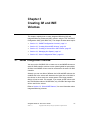
Chapter 1
Introduction to
Integrated RAID
This chapter provides an overview of the LSI Integrated RAID solution
for LSI SAS controllers, its features, and its benefits. The chapter
includes these sections:
•
Section 1.1, “Introduction,” page 1-1
•
Section 1.2, “Integrated RAID Benefits and Features,” page 1-2
•
Section 1.3, “Using this Manual,” page 1-3
You can use the LSI Integrated RAID solution with the following LSI SAS
controllers:
1.1
•
LSISAS1064/1064E
•
LSISAS1068/1068E
•
LSISAS1078
Introduction
The LSI Integrated RAID solution provides cost benefits for the server or
workstation market where the extra performance, storage capacity,
and/or redundancy of a RAID configuration are required. The
components of Integrated RAID are:
•
Integrated Mirroring (IM), which supports two-disk mirrored arrays
and hot spare disks.
•
Integrated Mirroring Enhanced (IME), which supports mirrored
arrays with three to ten disks, plus hot spare disks.
•
Integrated Striping (IS), which supports striped arrays with two to
ten disks.
Integrated RAID for SAS User’s Guide
Version 1.1
Copyright © 2006, 2007 by LSI Logic Corporation. All rights reserved.
1-1
By simplifying the configuration options and by providing firmware
support in its host adapters, LSI can offer the Integrated RAID solution
at a lower cost than a hardware RAID implementation.
Fusion-MPT™ firmware supports IM, IME, and IS volumes. You can
create up to two Integrated RAID storage volumes on the same LSI SAS
controller.
1.2
Integrated RAID Benefits and Features
Integrated RAID has the following benefits and features:
1-2
•
Support for up to ten disks per IME or IS volume, with one or two
storage volumes per SAS controller. Each controller can support up
to 12 volume disks, plus one or two hot spare disks, for a maximum
of 14 disks per controller. (Support for this number of disks requires
Integrated RAID firmware v1.20.00 or above.)
•
Support for two-disk IM mirrored volumes
•
Low cost RAID volume creation meets the needs of most internal
RAID installations
•
Easy to use - installation and configuration are not complex
•
System can boot from an IM, IME, or IS volume
•
No special OS-specific software required
•
High reliability and data integrity
–
Nonvolatile write journaling
–
Physical disks not visible to OS or to application software
•
Low host CPU and PCI bus utilization
•
Fusion-MPT architecture provides processing power
–
Shared memory architecture minimizes external memory
requests
–
Functionality is contained in device hardware and firmware
Introduction to Integrated RAID
Version 1.1
Copyright © 2006, 2007 by LSI Logic Corporation. All rights reserved.
1.3
Using this Manual
•
Chapters 2 and 3 of this User’s Guide list IM/IME features and
explain how to create IM/IME volumes and optional hot spare disks.
•
Chapters 4 and 5 list Integrated Striping features and explain how to
create Integrated Striping (IS) volumes.
•
Appendix A explains how to use the CFGGEN IR configuration utility
to create IM, IME, and IS volumes in the manufacturing environment.
Using this Manual
Version 1.1
1-3
Copyright © 2006, 2007 by LSI Logic Corporation. All rights reserved.
1-4
Introduction to Integrated RAID
Version 1.1
Copyright © 2006, 2007 by LSI Logic Corporation. All rights reserved.
Chapter 2
Overview of Integrated Mirroring
and Integrated Mirroring
Enhanced
This chapter provides an overview of the LSI Integrated Mirroring (IM)
and Integrated Mirroring Enhanced (IME) features. It includes these
sections:
2.1
•
Section 2.1, “Introduction,” page 2-1
•
Section 2.2, “IM and IME Features,” page 2-2
•
Section 2.3, “IM/IME Description,” page 2-3
•
Section 2.4, “Integrated RAID Firmware,” page 2-5
•
Section 2.5, “Fusion-MPT Support,” page 2-7
Introduction
As a result of the shift towards Network Attached Storage (NAS), ISPs
need a cost effective, fault-tolerant solution to protect the operating
systems on small form factor, high-density, rack-mountable servers. The
LSI Integrated Mirroring (IM) and Integrated Mirroring Enhanced (IME)
features provide data protection for the system boot volume to safeguard
critical information such as the operating system on servers and high
performance workstations. The IM and IME features provide a robust,
high-performance, fault-tolerant solution to data storage needs, at a
lower cost than a dedicated RAID controller.
The IM and IME features support one or two mirrored volumes per LSI
SAS controller, to provide fault-tolerant protection for critical data. The
two volumes can have up to twelve disk drives total, plus one or two hot
spare disks.
If a disk in an Integrated Mirroring volume fails, the hot swap capability
allows you to restore the volume by simply swapping disks. The firmware
then automatically re-mirrors the swapped disk. Additionally, each SAS
Integrated RAID for SAS User’s Guide
Version 1.1
Copyright © 2006, 2007 by LSI Logic Corporation. All rights reserved.
2-1
controller can have one or two global hot spare disks available to
automatically replace a failed disk in the IM or IME storage volumes on
the controller. Hot spares make the IM/IME volume even more faulttolerant.
Note:
You can also configure one IM or IME volume and one
Integrated Striping (IS) volume on the same LSI SAS
controller.
The IM/IME feature uses the same device drivers as the standard LSI
Fusion-MPT based controllers, providing seamless and transparent fault
tolerance. This eliminates the need for complex backup software or
expensive RAID hardware. The IM/IME feature operates independently
from the operating system, in order to conserve system resources. The
BIOS-based configuration utility makes it easy to configure IM and IME
volumes.
2.2
IM and IME Features
IM and IME support the following features:
2-2
•
Configurations of one or two IM or IME volumes on the same LSI
SAS controller. IM volumes have two mirrored disks; IME volumes
have three to ten mirrored disks. Two volumes can have up to 12
disks total. (Requires Integrated RAID firmware v1.20.00 or above.)
•
One or two global hot spare disks per controller, to automatically
replace failed disks in IM/IME volumes. (Support for two hot spares
requires Integrated RAID firmware v1.20.00 or above.) The hot
spares are in addition to the 12-disk maximum for two volumes per
SAS controller.
•
Mirrored volumes run in optimal mode or in degraded mode (if one
mirrored disk fails).
•
Hot swap capability.
•
Presents a single virtual drive to the OS for each IM/IME volume.
•
Supports both SAS and SATA disks. The two types of disks cannot
be combined in the same volume. However, an LSI SAS controller
can support one volume with SATA disks and a second volume with
SAS disks.
Overview of Integrated Mirroring and Integrated Mirroring Enhanced
Version 1.1
Copyright © 2006, 2007 by LSI Logic Corporation. All rights reserved.
2.3
•
Fusion-MPT architecture.
•
Easy-to-use BIOS-based configuration utility.
•
Error notification: the drivers update an OS-specific event log.
•
SES status LED support.
•
Write journaling, which allows automatic synchronization of
potentially inconsistent data after unexpected power-down situations.
•
Metadata used to store volume configuration on mirrored disks.
•
Automatic background resynchronization while host I/Os continue.
•
Background media verification ensures that data on IM/IME volumes
is always accessible.
IM/IME Description
The LSI Integrated RAID solution supports one or two IM/IME volumes
on each LSI SAS controller (or one IM/IME volume and one Integrated
Striping volume). Typically, one of these volumes is the boot volume, as
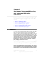
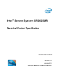
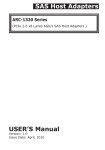
shown in Figure 2.1. Boot support is available through the firmware of the
LSI SAS controller that supports the standard Fusion-MPT interface. The
runtime mirroring of the boot disk is transparent to the BIOS, drivers, and
operating system. Host-based status software monitors the state of the
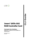
mirrored disks and reports any error conditions. Figure 2.1 shows an IM
implementation with a second disk as a mirror of the first (primary) disk.
IM/IME Description
Version 1.1
2-3
Copyright © 2006, 2007 by LSI Logic Corporation. All rights reserved.
Figure 2.1
Typical Integrated Mirroring Implementation
IM Volume
Primary
Mirror
SAS
NVSRAM
(For Write Journaling)
LSI
Fusion-MPT
Controller
Memory
Bus
FLASH
(For Configuration)
The advantage of an IM/IME volume is that there is always a second,
mirrored copy of the data. The disadvantage is that writes take longer
because data must be written twice. On the other hand, performance is
actually improved during reads.
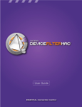
Figure 2.2 shows the logical view and physical view of an IM volume.
Figure 2.2
Logical View
Integrated Mirroring Volume
Physical View
LBA 1
LBA 1
LBA 2
LBA 2
LBA 3
LBA 3
LBA N
LBA N
LBA 1’
LBA 2’
+
LBA 3’
LBA N’
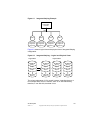
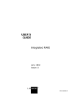
An IME volume can be configured with up to ten mirrored disks. (One or
two global hot spares can be added also.) Figure 2.3 shows the logical
view and physical view of an Integrated Mirroring Enhanced (IME)
volume with three mirrored disks. Each mirrored stripe is written to a disk
and mirrored to an adjacent disk. This type of configuration is also called
RAID 1E.
2-4
Overview of Integrated Mirroring and Integrated Mirroring Enhanced
Version 1.1
Copyright © 2006, 2007 by LSI Logic Corporation. All rights reserved.
Figure 2.3
Integrated Mirroring Enhanced with Three Disks
Logical View
Physical View
Mirrored Stripe 1
Mirrored Stripe 1
Mirrored Stripe 2
Mirrored Stripe 3
Mirrored Stripe 2
Mirrored Stripe 3’
Mirrored Stripe 1’
Mirrored Stripe 2’
Mirrored Stripe 3
Mirrored Stripe 4
Mirrored Stripe 5
Mirrored Stripe 4
Mirrored Stripe 6’
+
Mirrored Stripe 4’
Mirrored Stripe 6
+
Mirrored Stripe 5’
Mirrored Stripe 5
Mirrored Stripe 6
Mirrored Stripe n-2
Mirrored Stripe n-1
Mirrored Stripe n
Mirrored Stripe n’
Mirrored Stripe (n-2)’
Mirrored Stripe (n-1)’
Mirrored Stripe n
The LSI BIOS-based configuration utility enables you to create IM and
IME volumes during initial setup and to reconfigure them in response to
hardware failures or changes in the environment.
2.4
Integrated RAID Firmware
This section describes features of the LSI Integrated RAID firmware.
2.4.1
Resynchronization with Concurrent Host I/O Operation
The Integrated RAID firmware allows host I/Os to continue on an IM or
IME volume while the volume is being re-synchronized in the
background. Resynchronization is attempted after a hot spare is
activated due to a physical device failure, or after a hot swap has
occurred to a physical disk in the volume.
2.4.2
Metadata Support
The firmware supports metadata, which describes the IM/IME logical
drive configuration stored on each member disk. When the firmware is
initialized, each member disk is queried to read the stored metadata in
Integrated RAID Firmware
Version 1.1
Copyright © 2006, 2007 by LSI Logic Corporation. All rights reserved.
2-5
order to verify the configuration. The usable disk space for each member
disk is adjusted down when the configuration is created, in order to leave
room for this data.
2.4.3
Hot Swapping
The firmware supports hot swapping. The hot-swapped disk is
automatically resynchronized in the background, without any host or user
intervention. The firmware detects hot swap removal and disk insertion.
Following a hot swap event, the firmware readies the new physical disk
by spinning it up and verifying that it has enough capacity for the mirrored
volume. The firmware resynchronizes all hot-swapped disks that have
been removed, even if the same disk is re-inserted. In a two-disk
mirrored volume, the firmware marks the hot-swapped disk as the
secondary disk and marks the other mirrored disk as the primary disk.
The firmware resynchronizes all data from the primary disk onto the new
secondary disk.
2.4.4
SMART Support
SMART is a technology that monitors hard disk drives for signs of future
disk failure and generates an alert if such signs are detected. The
firmware polls each physical disk in the volume at regular intervals. If the
firmware detects a SMART ASC/ASCQ code on a physical disk in the
IM/IME volume, it processes the SMART data and stores it in nonvolatile
memory. The IM/IME volume does not support SMART directly, since it
is just a logical representation of the physical disks in the volume.
2.4.5
Hot Spare Disk
One or two disk drives per controller can be configured as global hot
spare disks, to protect data on the IM/IME volumes configured on the
controller. If the firmware fails one of the mirrored disks, it automatically
replaces the failed disk with a hot spare disk and then resynchronizes
the mirrored data. The firmware is automatically notified when the failed
disk has been replaced, and it then designates the failed disk as the new
hot spare.
2-6
Overview of Integrated Mirroring and Integrated Mirroring Enhanced
Version 1.1
Copyright © 2006, 2007 by LSI Logic Corporation. All rights reserved.
2.4.6
Media Verification
The firmware supports a background media verification feature that runs
at regular intervals when the IM/IME volume is in optimal state. If the
verification command fails for any reason, the other disk’s data for this
segment is read and written to the failing disk in an attempt to refresh
the data. The current Media Verification Logical Block Address is written
to nonvolatile memory occasionally to allow media verification to continue
approximately where it left off prior to a power-cycle.
2.4.7
Disk Write Caching
The firmware disables disk write caching by default for IM/IME volumes.
This is done to increase data integrity, so that the disk write log stored
in NVSRAM is always valid. If disk write caching were enabled (not
recommended), the disk write log could be invalid.
2.4.8
NVSRAM Usage
The Integrated RAID firmware requires at least a 32K NVSRAM in order
to perform write journaling. Write journaling is used to verify that the
disks in the IM/IME volume are synchronized with each other.
2.5
Fusion-MPT Support
The BIOS uses the LSI Fusion-MPT interface to communicate to the
SAS controller and firmware to enable IM and IME volumes. This
includes reading the Fusion-MPT configuration to access the parameters
that are used to define behavior between the SAS controller and the
devices connected to it. The Fusion-MPT drivers for all supported
operating systems implement the Fusion-MPT interface to communicate
with the controller and firmware.
Fusion-MPT Support
Version 1.1
Copyright © 2006, 2007 by LSI Logic Corporation. All rights reserved.
2-7
2-8
Overview of Integrated Mirroring and Integrated Mirroring Enhanced
Version 1.1
Copyright © 2006, 2007 by LSI Logic Corporation. All rights reserved.
Chapter 3
Creating IM and IME
Volumes
This chapter explains how to create Integrated Mirroring (IM) and
Integrated Mirroring Enhanced (IME) volumes using the LSI SAS BIOS
Configuration Utility (SAS BIOS CU). The chapter includes these topics:
3.1
•
Section 3.1, “IM/IME Configuration Overview,” page 3-1
•
Section 3.2, “Creating IM and IME Volumes,” page 3-2
•
Section 3.3, “Creating a Second IM or IME Volume,” page 3-5
•
Section 3.4, “Managing Hot Spares,” page 3-6
•
Section 3.5, “Other Configuration Tasks,” page 3-8
IM/IME Configuration Overview
You can use the SAS BIOS CU to create one or two IM/IME volumes on
each LSI SAS controller, with one or two optional global hot spare disks.
All disks in an IM/IME volume must be connected to the same LSI SAS
controller.
Although you can use disks of different size in IM and IME volumes, the
smallest disk in the volume will determine the logical size of all disks in
the volume. In other words, the excess space of the larger member
disk(s) will not be used. For example, if you create an IME volume with
two 100-GB disks and two 120-GB disks, only 100-GB of the larger disks
will be used for the volume.
Refer to Section 2.2, “IM and IME Features,” for more information about
Integrated Mirroring volumes.
Integrated RAID for SAS User’s Guide
Version 1.1
Copyright © 2006, 2007 by LSI Logic Corporation. All rights reserved.
3-1
3.2
Creating IM and IME Volumes
The SAS BIOS CU is part of the Fusion-MPT BIOS. When the BIOS
loads during boot and you see the message about the LSI Configuration
Utility, press Ctrl-C to start the CU. After you do this, the message
changes to:
Please wait, invoking SAS Configuration Utility...
After a brief pause, the main menu of the SAS BIOS CU appears. On
some systems, however, the following message appears next:
LSI Configuration Utility will load following
initialization!
In this case, the SAS BIOS CU will load after the system has completed
its power-on self test.
You can configure one or two IM or IME volumes per Fusion-MPT
controller. You can also configure one IM/IME and one Integrated Striping
(IS) volume on the same controller, up to a maximum of twelve physical
disk drives for the two volumes. In addition, you can create one or two
hot spares for the IM/IME array(s).
The following guidelines also apply when creating an IM or IME volume:
•
All physical disks in a volume must be either SATA (with extended
command set support) or SAS (with SMART support). SAS and
SATA disks cannot be combined in the same volume. However, you
can create one volume with SAS disks and a second volume with
SATA disks on the same controller.
•
Disks must have 512-byte blocks and must not have removable
media.
•
An IM volume must have two drives. An IME volume can have three
to ten drives. In addition, one or two hot spares can be created for
the IM/IME volume(s).
Note:
3-2
If a disk in an IM/IME volume fails, it is rebuilt on the global
hot spare if one is available. LSI recommends that you
always use hot spares with IM/IME volumes.
Creating IM and IME Volumes
Version 1.1
Copyright © 2006, 2007 by LSI Logic Corporation. All rights reserved.
3.2.1
Creating an IM Volume
Follow these steps to create an IM volume with the SAS BIOS CU:
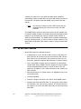
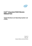
1. On the Adapter List screen, use the arrow keys to select an LSI SAS
adapter.
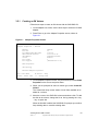
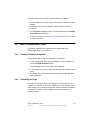
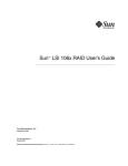
2. Press Enter to go to the Adapter Properties screen, shown in
Figure 3.1.
Figure 3.1
Adapter Properties Screen
LSI Logic MPT Setup Utility
Adapter Properties -- SAS1068
vx.xx.xx.xx
Adapter
PCI Slot
PCI Address(Bus/Dev/Func)
MPT Firmware Revision
SAS Address
Status
Boot Order
Boot Support
SAS1068
03
03:00:00
00.03.23.00-IT
500605B0:0000C580
Enabled
1
[Enabled BIOS & OS]
RAID Properties
SAS Topology
Advanced Adapter Properties
Esc = Exit Menu
Enter = Select Item
F1/Shift+1 = Help
-/+ = Change Item
3. On the Adapter Properties screen, use the arrow keys to select RAID
Properties on the screen and press Enter.
4. When you are prompted to select a volume type, select Create IM
Volume.
The Create New Array screen shows a list of disks available to be
added to a volume.
5. Move the cursor to the RAID Disk column and select a disk. To add
the disk to the volume, change the No to Yes by pressing the + key,
− key, or space bar.
When the first disk is added, the SAS BIOS CU prompts you to either
keep existing data or overwrite existing data.
Creating IM and IME Volumes
Version 1.1
Copyright © 2006, 2007 by LSI Logic Corporation. All rights reserved.
3-3
6. Press M to keep the existing data on the first disk or press D to
overwrite it.
If you keep the existing data, this is called a data migration. The first
disk will be mirrored onto the second disk, so any data you want to
keep must be on the first disk selected for the volume. Data on the
second disk is overwritten. The first disk must have 512-KB available
for metadata after the last partition.
As disks are added the Array Size field changes to reflect the size of
the new volume.
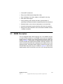
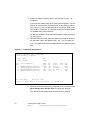
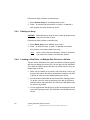
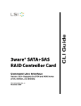
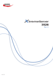
7. [Optional] Add one or two global hot spares by moving the cursor to
the hot spare column and pressing the + key, − key, or space bar.
Figure 3.2 shows an IM volume configured with one global hot spare
disk.
Figure 3.2
Create New Array Screen
LSI Logic MPT Setup Utility vx.xx.xx.xx
Create New Array -- SAS1068
Array Type:
Array Size(MB)
Slot
Num
1
2
8
11
IM
34332
Device Identifier
MAXTOR
MAXTOR
MAXTOR
MAXTOR
ATLAS15K2_36SAS
ATLAS15K2_36SAS
ATLAS15K2_36SAS
ATLAS15K2_36SAS
BG34
BG34
BG34
BG34
RAID
Disk
[Yes]
[Yes]
[No]
[No]
Hot
Spr
[No]
[No]
[Yes]
[No]
Esc = Exit Menu
F1/Shift+1 = Help
Space/+/- = Select disk for array or hot spare
Drive
Status
Primary
Secondary
Hot Spare
Ok
Pred
Fail
---------
Size
(MB)
35074
35074
35074
35074
C = Create array
8. When the volume has been fully configured, press C and then select
Save changes then exit this menu to commit the changes.
The SAS BIOS CU pauses while the array is being created.
3-4
Creating IM and IME Volumes
Version 1.1
Copyright © 2006, 2007 by LSI Logic Corporation. All rights reserved.
3.2.2
Creating an IME Volume
Follow these steps to create an IME volume with the SAS BIOS CU:
1. On the Adapter List screen, use the arrow keys to select an LSI SAS
adapter.
2. Press Enter to go to the Adapter Properties screen, shown in
Figure 3.1.
3. On the Adapter Properties screen, use the arrow keys to select RAID
Properties on the screen and press Enter.
4. When you are prompted to select a volume type, select Create IME
Volume.
The Create New Array screen shows a list of disks that can be added
to a volume.
5. Move the cursor to the RAID Disk column and select a disk. To add
the disk to the volume, change the No to Yes by pressing the + key,
− key, or space bar.
6. Repeat this step to select a total of three to ten disks for the volume.
All existing data on all the disks you select will be overwritten. As you
add disks, the Array Size field changes to reflect the size of the new
volume.
7. [Optional] Add one or two global hot spares to the volume by moving
the cursor to the hot spare column and pressing the + key, − key, or
space bar.
8. When the volume has been fully configured, press C and then select
Save changes then exit this menu to commit the changes.
The SAS BIOS CU pauses while the array is being created.
3.3
Creating a Second IM or IME Volume
The LSI SAS controllers allow you to configure two IM or IME volumes
per controller. If one volume is already configured, and if there are
available disk drives, there are two ways to add a second volume. The
first is as follows:
Creating a Second IM or IME Volume
Version 1.1
Copyright © 2006, 2007 by LSI Logic Corporation. All rights reserved.
3-5
1. In the configuration utility, select an adapter from the Adapter List.
Select the RAID Properties option.
This will display the current volume.
2. Press C to create a new volume.
3. Continue with step 4 of Section 3.2.1, “Creating an IM Volume” or
step 4 of Section 3.2.2, “Creating an IME Volume” to create a second
volume.
The other way to add a second volume is as follows:
1. On the Adapter List screen, use the arrow keys to select an LSI SAS
adapter.
2. Press Enter to go to the Adapter Properties screen, shown in
Figure 3.1.
3. On the Adapter Properties screen, use the arrow keys to select RAID
Properties and press Enter.
4. Continue with step 4 of Section 3.2.1, “Creating an IM Volume” or
step 4 of Section 3.2.2, “Creating an IME Volume” to create a second
volume.
3.4
Managing Hot Spares
You can create one or two global hot spare disks to protect the IM or IME
volumes on a SAS controller. Usually, you create global hot spares at the
same time you create the IM/IME volume. Follow these steps to add
global hot spare disks later:
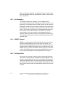
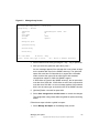
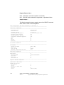
1. On the View Array screen, select Manage Array.
2. Select Manage Hot Spare on the Manage Array screen, shown in
Figure 3.3.
3-6
Creating IM and IME Volumes
Version 1.1
Copyright © 2006, 2007 by LSI Logic Corporation. All rights reserved.
Figure 3.3
Manage Array Screen
LSI Logic MPT Setup Utility
Manage Array -- SAS1068
Identifier
Type
Scan Order
Size(MB)
Status
vx.xx.xx.xx
LSILOGICLogical Volume
IM
1
34332
Optimal
3000
Manage Hot Spare
Synchronize Array
Activate Array
Delete Array
Esc = Exit Menu
F1/Shift+1 = Help
Enter = Choose array type to create
Esc = Return to Adapter Properties
3. Select a disk from the list by pressing the + key, − key, or space bar.
4. After you select the global hot spare disk, press C.
An error message appears if the selected disk is not at least as large
as the smallest disk used in the IM/IME volume(s). The global hot
spare disk must have 512-byte blocks, it cannot have removable
media, and the disk type must be either SATA with extended
command set support or SAS with SMART support.
If SATA disks are used for the IM/IME volume(s), the hot spare disk
must also be a SATA disk. If SAS disks are used, the hot spare disk
must also be a SAS disk. An error message appears if the selected
disk is not the same type as the disks used in the IM/IME volumes.
5. [Optional] Select a second hot spare disk.
6. Select Save changes then exit this menu to commit the changes.
The configuration utility pauses while the global hot spares are being
added.
Follow these steps to delete a global hot spare:
1. Select Manage Hot Spare on the Manage Array screen.
Managing Hot Spares
Version 1.1
Copyright © 2006, 2007 by LSI Logic Corporation. All rights reserved.
3-7
2. Select Delete Hot Spare and then press C.
If there are two hot spares, select which one you want to delete.
3. Select Save changes then exit this menu to commit the changes.
The configuration utility pauses while the global hot spare is being
removed.
3.5
Other Configuration Tasks
This section explains how to perform other configuration and
maintenance tasks for IM and IME volumes.
3.5.1
Viewing Volume Properties
Follow these steps to view the properties of volumes:
1. In the SAS BIOS CU, select an adapter from the Adapter List. Select
the RAID Properties option.
The properties of the current volume are displayed. If global hot
spares are defined, they are also listed.
Note:
If you create one volume using SAS disks, another volume
using SATA disks, and global hot spare disks, the hot spare
disks will only appear when you view the volume that has
the same type of disks as the hot spare disks.
2. If two volumes are configured, press Alt+N to view the other array.
3. To manage the current array, select the Manage Array item and
press Enter.
3.5.2
Synchronizing an Array
The Synchronize Array command forces the firmware to resynchronize
the data on the mirrored disks in the array. It is seldom necessary to use
this command, because the firmware automatically keeps the mirrored
data synchronized during normal operation. When you use this
command, one disk of the array is placed in the Degraded state until the
data on the mirrored disks has been resynchronized.
3-8
Creating IM and IME Volumes
Version 1.1
Copyright © 2006, 2007 by LSI Logic Corporation. All rights reserved.
Follow these steps to force the synchronization of a selected array:
1. Select Synchronize Array on the Manage Array screen.
2. Press Y to start the synchronization, or N to cancel it.
3.5.3
Activating an Array
An array can become inactive if, for example, it is removed from one
controller or computer and moved to another one. The Activate Array
option allows you to reactivate an inactive array that has been added to
a system. This option is only available when the selected array is
currently inactive.
Follow these steps to activate a selected array
1. Select Activate Array on the Manage Array screen.
2. Press Y to proceed with the activation, or press N to abandon it.
After a pause, the array will become active.
Note:
3.5.4
If there is a global hot spare disk on the controller to which
you have moved the array, the BIOS checks when you
activate the array to determine if the hot spare is
compatible with the new array. An error message appears
if the disks in the activated array are larger than the hot
spare disk or if the disks in the activated array are not the
same type as the hot spare disk (SATA versus SAS).
Deleting an Array
CAUTION:
Before deleting an array, be sure to back up all data on the
array that you want to keep.
Follow these steps to delete a selected array:
1. Select Delete Array on the Manage Array screen.
2. Press Y to delete the array.
After a pause, the array is deleted. If there is another remaining array
and one or two hot spare disks, the BIOS checks the hot spare disks
to determine if they are compatible with the remaining array. If they
are not compatible (too small or wrong disk type) the firmware
deletes them also.
Other Configuration Tasks
Version 1.1
Copyright © 2006, 2007 by LSI Logic Corporation. All rights reserved.
3-9
Note:
3.5.5
After a volume has been deleted, it cannot be recovered.
When an IM volume is deleted, the data is preserved on the
primary disk. When an IME volume is deleted, the master
boot records of all disks are deleted.
Locating a Disk Drive, or Multiple Disk Drives in a Volume
You can use the SAS BIOS CU to locate and identify a specific physical
disk drive by flashing the drive’s LED. You can also use the SAS BIOS
CU to flash the LEDs of all the disk drives in a RAID volume. There are
several ways to do this:
•
When you are creating an IM or IME volume, and a disk drive is set
to Yes as part of the volume, the LED on the disk drive is flashing.
The LED is turned off when you have finished creating the volume.
•
You can locate individual disk drives from the SAS Topology screen.
To do this, move the cursor to the name of the disk in the Device
Identifier column and press Enter. The LED on the disk flashes until
the next key is pressed.
•
You can locate all the disk drives in a volume by selecting the volume
on the SAS Topology screen. The LEDs flash on all disk drives in the
volume.
Note:
3.5.6
The LEDs on the disk drives will flash as described above
if the firmware is correctly configured and the drives or the
disk enclosure supports disk location.
Selecting a Boot Disk
You can select a boot disk in the SAS Topology screen. This disk is then
moved to scan ID 0 on the next boot, and remains at this position. This
makes it easier to set BIOS boot device options and to keep the boot
device constant during device additions and removals. There can be only
one boot disk.
Follow these steps to select a boot disk:
1. In the SAS BIOS CU, select an adapter from the Adapter List.
2. Select the SAS Topology option.
3-10
Creating IM and IME Volumes
Version 1.1
Copyright © 2006, 2007 by LSI Logic Corporation. All rights reserved.
The current topology is displayed. If the selection of a boot device is
supported, the bottom of the screen lists the Alt+B option. This is the
key for toggling the boot device. If a device is currently configured as
the boot device, the Device Info column on the SAS Topology screen
will show the word “Boot.”
3. To select a boot disk, move the cursor to the disk and press Alt+B.
4. To remove the boot designator, move the cursor down to the current
boot disk and press Alt+B. This controller will no longer have a disk
designated as boot.
5. To change the boot disk, move the cursor to the new boot disk and
press Alt+B. The boot designator will move to this disk.
Note:
The firmware must be configured correctly in order for the
Alt+B feature to work.
Other Configuration Tasks
Version 1.1
Copyright © 2006, 2007 by LSI Logic Corporation. All rights reserved.
3-11
3-12
Creating IM and IME Volumes
Version 1.1
Copyright © 2006, 2007 by LSI Logic Corporation. All rights reserved.
Chapter 4
Overview of
Integrated Striping
This chapter provides an overview of the LSI Integrated Striping (IS)
feature. It includes these sections:
4.1
•
Section 4.1, “Introduction,” page 4-1
•
Section 4.2, “IS Features,” page 4-2
•
Section 4.3, “IS Description,” page 4-2
•
Section 4.4, “Integrated Striping Firmware,” page 4-4
•
Section 4.5, “Fusion-MPT Support,” page 4-4
Introduction
The LSI Integrated Striping (IS) feature is useful for applications that
require the faster performance and increased storage capacity of
striping. The low-cost IS feature has many of the advantages of a more
expensive RAID striping solution. A single IS logical drive may be
configured as the boot disk or as a data disk.
The IS feature is implemented with controller firmware that supports the
Fusion-MPT Interface. IS provides better performance and more capacity
than individual disks, without burdening the host CPU. The firmware
splits host I/Os over multiple disks and presents the disks as a single
logical drive. In general, striping is transparent to the BIOS, the drivers,
and the operating system.
The SAS BIOS CU is used to configure IS volumes, which can consist
of two to ten disks.
Integrated RAID for SAS User’s Guide
Version 1.1
Copyright © 2006, 2007 by LSI Logic Corporation. All rights reserved.
4-1
4.2
IS Features
Integrated Striping supports the following features:
•
Support for volumes with two to ten disks
•
Support for two IS volumes (or one IS volume and one IM/IME
volume) on a controller, with up to 12 disks total. (Requires
Integrated RAID firmware v1.20.00 or above.)
Note:
4.3
All physical disks in a volume must be connected to the
same SAS controller.
•
Presents a single virtual drive to the OS for each configured volume
•
Support for both SAS and SATA drives, although the two types of
drives cannot be combined in one volume
•
Fusion-MPT architecture
•
Easy-to-use SAS BIOS configuration utility
•
Error notification
•
Use of metadata to store volume configuration on disks
•
OS-specific event log
•
Error display inside the Fusion-MPT BIOS
•
SES status LED support for drives used in IS volumes
IS Description
The IS feature writes data across multiple disks instead of onto one disk.
This is accomplished by partitioning each disk’s storage space into
64-KB stripes. These stripes are interleaved round-robin, so that the
combined storage space is composed alternately of stripes from each
disk.
For example, as shown in Figure 4.1, segment 1 is written to disk 1,
segment 2 is written to disk 2, segment 3 is written to disk 3, and so on.
When the system reaches the end of the disk list, it continues writing
data at the next available segment of disk 1.
4-2
Overview of Integrated Striping
Version 1.1
Copyright © 2006, 2007 by LSI Logic Corporation. All rights reserved.
Figure 4.1
Integrated Striping Example
LSI
Fusion-MPT
Controller
SAS
Disk 1
Disk 2
Disk 3
Disk 4
Segment 1
Segment 5
Segment 9
Segment 2
Segment 6
Segment 10
Segment 3
Segment 7
Segment 11
Segment 4
Segment 8
Segment 12
Figure 4.2 shows a logical view and a physical view of Integrated Striping
configuration.
Figure 4.2
Integrated Striping - Logical and Physical Views
Logical View
Physical View
Stripe 1
Stripe 1
Stripe 2
Stripe 4
Stripe 3
Stripe 7
Stripe N
Stripe N-2
Stripe 2
Stripe 3
Stripe 5
+
Stripe 8
Stripe N-1
Stripe 6
+
Stripe 9
Stripe N
The primary advantage of IS is speed, because it transfers data to or
from multiple disks at once. However, there is no data redundancy;
therefore, if one disk fails, that data is lost.
IS Description
Version 1.1
4-3
Copyright © 2006, 2007 by LSI Logic Corporation. All rights reserved.
4.4
Integrated Striping Firmware
This section describes features of the LSI Integrated RAID firmware.
4.4.1
Metadata Support
The firmware supports metadata, which describes the IS logical drive
configuration stored on each member disk. When the firmware is
initialized, each member disk is queried to read the stored metadata to
verify the configuration. The usable disk space for each IS member disk
is adjusted down when the configuration is created, in order to leave
room for this data.
4.4.2
SMART Support
SMART is a technology that monitors hard disk drives for signs of future
disk failure and generates an alert if such signs are detected. The
firmware polls each physical disk in the volume at regular intervals. If the
firmware detects a SMART ASC/ASCQ code on a physical disk in the IS
volume, it processes the SMART data and stores it in nonvolatile
memory. The IS volume does not support SMART directly, since it is just
a logical representation of the physical disks in the volume.
4.4.3
Disk Write Caching
Disk write caching is enabled by default on all IS volumes.
4.5
Fusion-MPT Support
The BIOS uses the LSI Fusion-MPT interface to communicate to the
SAS controller and firmware to enable IS. This includes reading the
Fusion-MPT configuration to gain access to the parameters that are used
to define behavior between the SAS controller and the devices
connected to it. The Fusion-MPT drivers for all supported operating
systems implement the Fusion-MPT interface to communicate with the
controller and firmware.
4-4
Overview of Integrated Striping
Version 1.1
Copyright © 2006, 2007 by LSI Logic Corporation. All rights reserved.
Chapter 5
Creating Integrated
Striping Volumes
This chapter explains how to create Integrated Striping (IS) volumes
using the LSI SAS BIOS Configuration Utility (SAS BIOS CU). The
chapter includes these topics:
5.1
•
Section 5.1, “IS Configuration Overview,” page 5-1
•
Section 5.2, “Creating IS Volumes,” page 5-2
•
Section 5.3, “Creating a Second IS Volume,” page 5-4
•
Section 5.4, “Other Configuration Tasks,” page 5-5
IS Configuration Overview
You can use the SAS BIOS CU to create one or two IS volumes, with up
to twelve drives total, on an LSI SAS controller. Each volume can have
from two to ten drives. Disks in an IS volume must be connected to the
same LSI SAS controller, and the controller must be in the BIOS boot
order.
Although you can use disks of different size in IS volumes, the smallest
disk determines the “logical” size of each disk in the volume. In other
words, the excess space of the larger member disk(s) is not used.
Usable disk space for each disk in an IS volume is adjusted down to
leave room for metadata. Usable disk space may be further reduced to
maximize the ability to interchange disks in the same size classification.
The supported stripe size is 64 kilobytes.
Refer to Section 4.2, “IS Features,” for more information about Integrated
Striping volumes.
Integrated RAID for SAS User’s Guide
Version 1.1
Copyright © 2006, 2007 by LSI Logic Corporation. All rights reserved.
5-1
5.2
Creating IS Volumes
The SAS BIOS CU is part of the Fusion-MPT BIOS. When the BIOS
loads during boot and you see the message about the LSI Configuration
Utility, press Ctrl-C to start it. After you do this, the message changes to:
Please wait, invoking SAS Configuration Utility...
After a brief pause, the main menu of the SAS BIOS CU appears. On
some systems, however, the following message appears next:
LSI Logic Configuration Utility will load following
initialization!
In this case, the SAS BIOS CU will load after the system has completed
its power-on self test.
Follow the steps below to configure an Integrated Striping (IS) volume
with the SAS BIOS CU. The procedure assumes that the required
controller(s) and disks are already installed in the computer system. You
can configure an IM/IME volume and an IS volume on the same SAS
controller.
1. On the Adapter List screen of the SAS BIOS CU, use the arrow keys
to select a SAS adapter.
2. Press Enter to go to the Adapter Properties screen, shown in
Figure 5.1.
5-2
Creating Integrated Striping Volumes
Version 1.1
Copyright © 2006, 2007 by LSI Logic Corporation. All rights reserved.
Figure 5.1
Adapter Properties Screen
LSI Logic MPT Setup Utility
Adapter Properties -- SAS1068
vx.xx.xx.xx
Adapter
PCI Slot
PCI Address(Bus/Dev/Func)
MPT Firmware Revision
SAS Address
Status
Boot Order
Boot Support
SAS1068
03
03:00:00
00.03.23.00-IT
500605B0:0000C580
Enabled
1
[Enabled BIOS & OS]
RAID Properties
SAS Topology
Advanced Adapter Properties
Esc = Exit Menu
Enter = Select Item
F1/Shift+1 = Help
-/+ = Change Item
3. On the Adapter Properties screen, use the arrow keys to select RAID
Properties and press Enter.
4. When you are prompted to select a volume type, select Create IS
Volume.
The Create New Array screen shows a list of disks that can be added
to a volume.
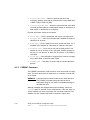
5. Move the cursor to the RAID Disk column. To add a disk to the
volume, change the No to Yes by pressing the + key, − key, or space
bar. As disks are added, the Array Size field changes to reflect the
size of the new volume.
There are several limitations when creating an IS (RAID 0) volume:
–
All disks must be either SATA (with extended command set
support) or SAS (with SMART support).
–
Disks must have 512-byte blocks and must not have removable
media.
–
There must be at least two and no more than ten drives in a valid
IS volume. Hot spare drives are not allowed.
Creating IS Volumes
Version 1.1
Copyright © 2006, 2007 by LSI Logic Corporation. All rights reserved.
5-3
Figure 5.2 shows an IS volume configured with two drives.
Figure 5.2
Create New Array Screen
LSI Logic MPT Setup Utility
Create New Array -- SAS1068
vx.xx.xx.xx
Array Type:
Array Size(MB)
Slot
Num
1
2
8
11
IS
70032
Device Identifier
MAXTOR
MAXTOR
MAXTOR
MAXTOR
ATLAS15K2_36SAS
ATLAS15K2_36SAS
ATLAS15K2_36SAS
ATLAS15K2_36SAS
BG34
BG34
BG34
BG34
RAID
Disk
[Yes]
[Yes]
[No]
[No]
Hot
Spr
[No]
[No]
[No]
[No]
Esc = Exit Menu
F1/Shift+1 = Help
Space/+/- = Select disk for array or hot spare
Drive
Status
Ok
Ok
Ok
Ok
Pred
Fail
---------
Size
(MB)
35074
35074
35074
35074
C = Create array
6. When you have added the desired number of disks to the array,
press C and then select Save changes then exit this menu to
commit the changes. The configuration utility pauses while the array
is being created.
5.3
Creating a Second IS Volume
The LSI SAS controllers allow you to configure two IS volumes, or an IS
volume and an IM/IME volume. If one volume is already configured, and
if there are available disk drives, there are two ways to add a second
volume. The first is as follows:
1. In the configuration utility, select an adapter from the Adapter List.
Select the RAID Properties option.
This will display the current volume.
2. Press C to create a new volume.
3. Continue with step 4 of Section 5.2, “Creating IS Volumes,” to create
a second IS volume.
5-4
Creating Integrated Striping Volumes
Version 1.1
Copyright © 2006, 2007 by LSI Logic Corporation. All rights reserved.
The other way in which to add a second volume is as follows:
1. On the Adapter List screen, use the arrow keys to select an LSI SAS
adapter.
2. Press Enter to go to the Adapter Properties screen, shown in
Figure 5.1.
3. On the Adapter Properties screen, use the arrow keys to select RAID
Properties and press Enter.
4. Continue with step 4 of Section 5.2, “Creating IS Volumes,” to create
a second IS volume.
5.4
Other Configuration Tasks
This section explains how to perform other configuration and
maintenance tasks for IS volumes.
5.4.1
Viewing IS Volume Properties
Follow these steps to view the properties of IS volumes:
1. In the configuration utility, select an adapter from the Adapter List.
Select the RAID Properties option.
The properties of the current volume are displayed.
2. If more than one volume is configured, press Alt+N to view the next
array.
3. To manage the current array, press Enter when the Manage Array
item is selected.
5.4.2
Activating an Array
An array can become inactive if, for example, it is removed from one
controller or computer and moved to another one. The “Activate Array”
option allows you to reactivate an inactive array that has been added to
a system. This option is only available when the selected array is
currently inactive.
Other Configuration Tasks
Version 1.1
Copyright © 2006, 2007 by LSI Logic Corporation. All rights reserved.
5-5
Follow these steps to activate a selected array.
1. Select Activate Array on the Manage Array screen.
2. Press Y to proceed with the activation, or press N to abandon it.
After a pause, the array will become active.
5.4.3
Deleting an Array
CAUTION:
Before deleting an array, be sure to back up all data on the
array that you want to keep.
Follow these steps to delete a selected array:
1. Select Delete Array on the Manage Array screen.
2. Press Y to delete the array, or press N to abandon the deletion.
After a pause, the firmware deletes the array.
Note:
5.4.4
Once a volume has been deleted, it cannot be recovered.
The master boot records of all disks are deleted.
Locating a Disk Drive, or Multiple Disk Drives in a Volume
You can use the SAS BIOS CU to locate and identify a specific physical
disk drive by flashing the drive’s LED. You can also use the SAS BIOS
CU to flash the LEDs of all the disk drives in a RAID volume. There are
several ways to do this:
5-6
•
When you are creating an IS volume, and a disk drive is set to Yes
as part of the volume, the LED on the disk drive is flashing. The LED
is turned off when you have finished creating the volume.
•
You can locate individual disk drives from the SAS Topology screen.
To do this, move the cursor to the name of the disk in the Device
Identifier column and press Enter. The LED on the disk flashes until
the next key is pressed.
•
You can locate all the disk drives in a volume by selecting the volume
on the SAS Topology screen. The LEDs flash on all disk drives in the
volume.
Creating Integrated Striping Volumes
Version 1.1
Copyright © 2006, 2007 by LSI Logic Corporation. All rights reserved.
Note:
5.4.5
The LEDs on the disk drives will flash as described above
if the firmware is correctly configured and the drives or the
disk enclosure supports disk location.
Selecting a Boot Disk
You can select a boot disk in the SAS Topology screen. This disk is then
moved to scan ID 0 on the next boot, and remains at this position. This
makes it easier to set BIOS boot device options and to keep the boot
device constant during device additions and removals. There can be only
one boot disk.
Follow these steps to select a boot disk:
1. In the SAS BIOS CU, select an adapter from the Adapter List.
2. Select the SAS Topology option.
The current topology is displayed. If the selection of a boot device is
supported, the bottom of the screen lists the Alt+B option. This is the
key for toggling the boot device. If a device is currently configured as
the boot device, the Device Info column on the SAS Topology screen
will show the word “Boot.”
3. To select a boot disk, move the cursor to the disk and press Alt+B.
4. To remove the boot designator, move the cursor down to the current
boot disk and press Alt+B. This controller will no longer have a disk
designated as boot.
5. To change the boot disk, move the cursor to the new boot disk and
press Alt+B. The boot designator will move to this disk.
Note:
The firmware must be configured correctly in order for the
Alt+B feature to work.
Other Configuration Tasks
Version 1.1
Copyright © 2006, 2007 by LSI Logic Corporation. All rights reserved.
5-7
5-8
Creating Integrated Striping Volumes
Version 1.1
Copyright © 2006, 2007 by LSI Logic Corporation. All rights reserved.
Appendix A
Using the CFGGEN IR
Configuration Utility
This Appendix describes how to use the CFGGEN IR Configuration
Utility to create Integrated Mirroring (IM), Integrated Mirroring Enhanced
(IME), and Integrated Striping (IS) volumes on LSI SAS controllers.
CFGGEN is a command line utility that runs in the DOS, Linux, EFI, and
Windows Pre-Installation (WinPE) environments. CFGGEN is a minimally
interactive program that can be executed from a command line prompt
or a shell script.
The Appendix includes these topics:
•
Section A.1, “Hardware and Software Requirements,” page A-2
•
Section A.2, “CFGGEN Interface Description,” page A-3
•
Section A.3, “CFGGEN Commands,” page A-3
Note:
CFGGEN is intended for use only in the manufacturing
environment. End users can use the BIOS-based
configuration utility to create IM, IME, and IS volumes. (See
Chapter 3, “Creating IM and IME Volumes” and Chapter 5,
“Creating Integrated Striping Volumes.”)
Integrated RAID for SAS User’s Guide
Version 1.1
Copyright © 2006, 2007 by LSI Logic Corporation. All rights reserved.
A-1
A.1
Hardware and Software Requirements
The CFGGEN IR Configuration Utility runs on any Intel IA-32 or IA64
compatible platform. It works with storage devices that are compliant with
existing SCSI standards. CFGGEN supports the LSISAS1064/1064E,
LSISAS1068/1068E, and LSISAS1078 LSI SAS controller chips.
CFGGEN runs in the following operating environments:
DOS –
CFGGEN runs in any environment that is fully DOS compatible and has
at least 640-KB of memory. The system BIOS must support 32-bit BIOS
services, including the PCI BIOS services. CFGGEN uses these services
to locate the controller and its interface registers. CFGGEN must be able
to directly access the controller chip’s interface registers.
Note:
You cannot run CFGGEN in a virtual DOS window from
within Windows.
EFI –
CFGGEN runs in any environment that is fully EFI compatible.
Linux –
CFGGEN is a statically linked Linux application. Static linking prevents
any library version compatibility problems that might stop CFGGEN from
working with a specific release or distribution of Linux. Version 3.02.04
or newer of the LSI mptlinux driver must be installed on the system. The
required modules include mptbase.o, mptscsih.o, and mptctl.o.
Caution:
mptbase.o, mptscsih.o, and mptctl.o must be loaded
into the Linux kernel before CFGGEN will function correctly.
They can be loaded using the Linux modprobe command.
WinPE –
CFGGEN runs in Windows Pre-Installation Environment (WinPE) and is
statically compiled with the LSI MptLib Library (MptLib.lib). The WinPE
environment must have the appropriate LSI MPT Windows driver
(Miniport or Storport) installed and loaded in order to recognize and
communicate with the I/O controller.
A-2
Using the CFGGEN IR Configuration Utility
Version 1.1
Copyright © 2006, 2007 by LSI Logic Corporation. All rights reserved.
A.2
CFGGEN Interface Description
CFGGEN uses a command line interface. Commands are formatted as
follows:
cfggen <controller #> <command> <parameters>
The program name, controller number, command, and parameters fields
must be separated by the ASCII space character. The parameter format
is command specific, as described in Section A.3, “CFGGEN
Commands.”
Information is passed between the user environment and CFGGEN via
the command line, the standard output and standard error interfaces, and
the program return value. The user can redirect the output streams. The
return value is generated when the program exits. A value of 0 is
returned if the command is successful. Otherwise, a value of 1 is
returned.
A.3
CFGGEN Commands
CFGGEN has the following commands:
•
CREATE
•
DEFAULTS (called DELETE in the EFI version)
•
DISPLAY
•
FORMAT
•
HOTSPARE
•
STATUS
•
SETOFFLINE (DOS, Linux, and WinPE versions only)
•
SETONLINE (DOS, Linux, and WinPE versions only)
•
AUTO (EFI version only)
•
DISABLEIR (EFI version only)
•
ENABLEIR (EFI version only)
•
LIST (EFI version only)
CFGGEN Interface Description
Version 1.1
Copyright © 2006, 2007 by LSI Logic Corporation. All rights reserved.
A-3
CFGGEN is not case sensitive. You can type CFGGEN commands and
parameters in uppercase, lowercase, or a mixture of the two.
The following conventions are used in the command descriptions:
A.3.1
•
Text in italics must be entered exactly as shown on the command line.
•
Text surrounded by <> must be replaced with a required parameter.
•
Text surrounded by [ ] may be replaced by an optional parameter.
•
Parameters surrounded by {} must be entered one or more times, as
is appropriate for the command being executed.
•
The command line definition characters <>, [ ], and {} must not be
entered on the command line.
Common Command Line Parameters
This section describes CFGGEN command line parameters that are
common to more than one command.
•
<controller #>
The unique controller number of a PCI function found in the system,
starting with controller # 0. For example, in a system containing two
SAS1068 controllers, controller # 0 references the first controller and
controller # 1 references the other controller.
Valid controller number values are 0 to 255 (decimal).
•
<SCSI ID>
The SCSI bus address of a peripheral device attached to an LSI SAS
controller. The valid SCSI ID values for supported LSI SAS
controllers are 0 to 127 (decimal) per controller.
Note:
•
A-4
With PBSRAM, the SAS1068/1068E controllers can
support more than 128 devices.
<Enclosure:Bay>
The Enclosure and bay/slot of a peripheral device attached to the
bus. The argument must use a colon (:) as a separator and must
follow the enclosure:bay format. This argument is only valid when
used with the bay command line argument. Valid numbers are 0 to
127 (decimal).
Using the CFGGEN IR Configuration Utility
Version 1.1
Copyright © 2006, 2007 by LSI Logic Corporation. All rights reserved.
A.3.2
CREATE Command
The CREATE command creates IM, IME, and IS volumes on supported
LSI SAS controllers.
When a disk drive is added to an IM, IME, or IS volume, its entire storage
capacity may or may not be used, depending on drive capacity and
volume capacity. For example, if you add a 36-GB disk drive to a volume
that only uses 9-GB of capacity on each disk drive, the remaining 27-GB
of capacity on the disk drive is unusable.
The disk identified by the first SCSI ID on the command line is assigned
as the primary disk drive when an IM volume is created. If the controller
is allowed to resync the disk drives, the data on the primary disk drive
will be available when you access the newly created volume.
The following rules must be observed when creating IM, IME, and IS
volumes and hot spare disks:
1. All disks that are part of a volume, including global hot spares, must
be on the same SAS controller.
2. A maximum of two IM, IME, or IS volumes per controller can be
created.
3. The total number of disks in a volume cannot exceed ten, and the
total number of disks combined for two volumes cannot exceed
twelve. In addition, one or two hot spare disks can be created per
controller to support IM and IME volumes, for a maximum of 14
supported disks per SAS controller. (Support for this number of disks
requires Integrated RAID firmware v1.20.00 or above.)
4. An IM volume must have exactly two disks.
5. An IME volume can have a minimum of three disks and a maximum
of ten disks, as long as rule 3 is not violated.
Command Line –
cfggen <controller #> create <volume type> <size>
{<SCSI ID>} [qsync] [noprompt]
cfggen <controller #> create <volume type> <size> bay
{<enclosure:bay>} [qsync] [noprompt]
CFGGEN Commands
Version 1.1
Copyright © 2006, 2007 by LSI Logic Corporation. All rights reserved.
A-5
Parameters –
•
<controller #> – Number of the SAS controller targeted by this
command.
•
<volume type> – Volume type for the new volume to be created.
Valid values are IM or IME or IS.
•
<size> – Size of the RAID volume in megabytes, or MAX for the
maximum size available.
•
Bay – This option indicates that enclosure:bay values are specified
instead of SCSI ID values.
•
<SCSI ID> – SCSI ID of a hard disk drive to be included in the RAID
volume.
•
<enclosure:bay> – The enclosure:bay value for the disk drive to be
included in the RAID volume. These values can be obtained from the
output of the DISPLAY command.
•
qsync – If this optional parameter is specified, a quick
synchronization of new volume will be performed. If the volume type
is IME or IS, a quick synchronization is always performed even if
qsync is not specified. A quick synchronization means that the first
32-KB of the drives in the volume are cleared to 0.
•
noprompt – Suppresses display of warnings and prompts.
Program Return Value –
0x00
0x01
A.3.3
SUCCESS: command completed successfully.
FAILURE: bad command line arguments or operational failure.
DEFAULTS Command
Note:
This command is called DELETE in the EFI version of
CFGGEN.
The DEFAULTS (DELETE) command deletes any IM, IME, and IS
volumes and hot spare drives created by the CREATE and HOTSPARE
commands. No other controller configuration parameters are changed.
A-6
Using the CFGGEN IR Configuration Utility
Version 1.1
Copyright © 2006, 2007 by LSI Logic Corporation. All rights reserved.
Command Line –
DOS, Linux, WinPE versions:
cfggen <controller #> defaults [noprompt]
EFI version:
cfggen <controller #> delete [noprompt]
Parameters –
•
<controller #> – Number of the SAS controller targeted by this
command.
•
noprompt – Suppresses display of warnings and prompts.
Program Return Value –
0x00
0x01
A.3.4
SUCCESS: command completed successfully.
FAILURE: bad command line arguments or operational failure.
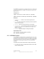
DISPLAY Command
The DISPLAY command displays configuration information for the
supported SAS controllers. The information includes controller type,
firmware version, BIOS version, volume information, and physical drive
information. An example of the information that will be output by this
command is provided in Sample Output below.
Note:
1 megabyte = 1,048,576 bytes. All sizes displayed in
megabytes are rounded down to the nearest megabyte.
Command Line –
cfggen <controller #> display [filename]
Parameters –
•
<controller #> – Number of the SAS controller targeted by this
command.
•
[filename] – Optional valid filename to store the output of the
command to a file.
CFGGEN Commands
Version 1.1
Copyright © 2006, 2007 by LSI Logic Corporation. All rights reserved.
A-7
Program Return Value –
0x00
0x01
SUCCESS: command completed successfully.
FAILURE: bad command line arguments or operational failure.
Sample Output –
The following example shows a sample output of the CREATE command
when used to create an IM configuration.
Read configuration has been initiated for controller 0
-----------------------------------------------------------------------Controller information
-----------------------------------------------------------------------Controller type
: LSI1064/1068
BIOS version
: 6.05.05.00
Firmware version
: 0.07.01.00
SCSI channel description
: 1 Serial Attached SCSI
Initiator IDs (SCSI ID)
: 63
Maximum physical devices
: 62
Concurrent commands supported
: 511
Slot
: 1
Bus
: 2
Device
: 2
Function
: 0
-----------------------------------------------------------------------IR Volume information
-----------------------------------------------------------------------IR volume 1
Status of volume
: Okay (OKY)
RAID level
: 1
Size (in MB)
: 34332
Physical hard disks (SCSI ID)
: 10 7
-----------------------------------------------------------------------Enclosure information
-----------------------------------------------------------------------Enclosure #
: 1
Enlcosure WWN
: 12345678:ABCDABCD
Start Slot
: 1
Num Slots
: 4
Start SCSI ID
: 0
-----------------------------------------------------------------------Physical device information
-----------------------------------------------------------------------Initiator at SCSI ID 63
Target on SCSI ID 7
Enclosure #
: 1
Slot #
: 1
Device is a Hard disk
SCSI ID
: 7
State
: Online (ONL)
A-8
Using the CFGGEN IR Configuration Utility
Version 1.1
Copyright © 2006, 2007 by LSI Logic Corporation. All rights reserved.
Size (in MB)/(in sectors)
Manufacturer
Model Number
Firmware Revision
Serial No
Drive Type
Target on SCSI ID 8
Enclosure #
Slot #
Device is a Hard disk
SCSI ID
State
Size (in MB)/(in sectors)
Manufacturer
Model Number
Firmware Revision
Serial No
Drive Type
Target on SCSI ID 9
Enclosure #
Slot #
Device is a Hard disk
SCSI ID
State
Size (in MB)/(in sectors)
Manufacturer
Model Number
Firmware Revision
Serial No
Drive Type
Target on SCSI ID 10
Enclosure #
Slot #
Device is a Hard disk
SCSI ID
State
Size (in MB)/(in sectors)
Manufacturer
Model Number
Firmware Revision
Serial No
Drive Type
:
:
:
:
:
:
34732/71132958
MAXTOR
ATLAS15K2_036SAS
BG31
E204EY1K
SAS
: 1
: 2
:
:
:
:
:
:
:
:
8
Hot Spare (HSP)
35074/71833095
MAXTOR
ATLAS15K2_36SAS
BG34
E207AY6K
SAS
: 1
: 3
:
:
:
:
:
:
:
:
9
Ready (RDY)
34732/71132959
MAXTOR
ATLAS15K2_036SAS
BG31
E204ERCK
SAS
: 1
: 4
:
:
:
:
:
:
:
:
10
Online (ONL)
140299/287332383
MAXTOR
ATLAS15K2_147SAS
BG34
E803YMCK
SAS
Logical drive status values are as follows:
•
Okay (OKY) – Volume is Active and drives are functioning properly.
User data is protected if the volume is IM or IME.
•
Degraded (DGD) – Volume is Active. User data is not fully protected
due to a configuration change or drive failure.
•
Rebuilding (RBLD) – Data resync or rebuild may be in progress.
CFGGEN Commands
Version 1.1
Copyright © 2006, 2007 by LSI Logic Corporation. All rights reserved.
A-9
•
Inactive, Okay (OKY) – Volume is inactive and drives are
functioning properly. User data is protected if the current RAID level
is RAID 1 (IM) or RAID 1E (IME).
•
Inactive, Degraded (DGD) – Volume is inactive and the user’s data
is not fully protected due to a configuration change or drive failure; a
data resync or rebuild may be in progress.
Physical drive status values are as follows:
A.3.5
•
Online (ONL) – Drive is operational and is part of a logical drive.
•
Hot Spare (HSP) – Drive is a hot spare that is available to replace a
failed drive in an array.
•
Ready (RDY) – Drive is ready for use as a normal disk drive; or it is
available to be assigned to a disk array or used as a hot spare.
•
Available (AVL) – Drive may or may not be ready, and it is not
suitable for use in an array or as a hot spare. Possible reasons for
this are: it is not spun up, its block size is incorrect, or its media is
removable.
•
Failed (FLD) – Drive was part of a logical drive or was a hot spare
drive, and it failed. It has been taken offline.
•
Standby (SBY) – This status is used to tag all non-hard disk drive
devices.
FORMAT Command
The FORMAT command is used to perform a low-level format of a disk
drive. The drive cannot be a hot spare drive or a member of an IM, IME,
or IS volume.
WARNING: A low-level format erases all data on the hard disk drive.
The FORMAT command cannot and should not be
interrupted; doing so may result in irreparable damage to
the hard disk drive.
Warning messages are displayed during the formatting, unless the
noprompt option is included on the command line. If the user does not
quickly respond to a series of prompts, the command is aborted. The
answers are case sensitive and must be entered in upper case.
A-10
Using the CFGGEN IR Configuration Utility
Version 1.1
Copyright © 2006, 2007 by LSI Logic Corporation. All rights reserved.
The FORMAT command does not complete and return to a shell prompt
until the format operation is complete. This may take a long time for a
large disk drive.
Command Line –
cfggen <controller #> format <SCSI ID> [noprompt]
cfggen <controller #> format bay <enclosure:bay> [noprompt]
Parameters –
•
<controller #> – Number of the controller targeted by this
command.
•
Bay – This option indicates that enclosure:bay values are specified
instead of SCSI ID values.
•
<SCSI ID> – SCSI ID of the hard disk drive to be formatted.
•
<enclosure:bay> – The enclosure:bay value for the disk drive to be
formatted. These values can be obtained from the output of the
DISPLAY command.
•
noprompt – Suppresses display of warnings and prompts.
Program Return Value –
0x00
0x01
A.3.6
SUCCESS: command completed successfully.
FAILURE: command failed.
HOTSPARE Command
The HOTSPARE command creates a hot spare disk drive. One or two
hot spare disk can be created per controller. The capacity of a hot spare
disk must be greater than or equal to the capacity of the smallest disk in
the logical drive. An easy way to verify this is to use the DISPLAY
command.
The following rules must be observed when creating hot spare disks:
1. A hot spare disk cannot be created unless at least one IM or IME
volume is already created.
CFGGEN Commands
Version 1.1
Copyright © 2006, 2007 by LSI Logic Corporation. All rights reserved.
A-11
2. CFGGEN does not allow adding a hot spare disk of a type
(SAS/SATA) that is different from the disk types in any of the
volumes.
Command Line –
cfggen <controller #> hotspare <SCSI ID>
cfggen <controller #> hotspare bay <enclosure:bay>
Parameters –
•
<controller #> – Number of the SAS controller targeted by this
command.
•
Bay – This option indicates that enclosure:bay values are specified
instead of SCSI ID values.
•
<SCSI ID> – SCSI ID of the drive targeted by this command.
•
<enclosure:bay> – The enclosure:bay value for the disk drive to use
for the new hot spare disk. These values can be obtained via the
output of the DISPLAY command.
Program Return Value –
0x00
0x01
A.3.7
SUCCESS: command completed successfully.
FAILURE: bad command line arguments or operational failure.
STATUS Command
The STATUS command displays the status of any volume
synchronization operation that is currently in progress on the controller.
If no such operation is in progress, CFGGEN displays a message
indicating this before it exits. The STATUS command adds the flag
Inactive to the Volume State field, if the controller firmware marks the
volume as Inactive.
Command Line –
cfggen <controller #> status
Parameters –
•
A-12
<controller #> – Number of the SAS controller targeted by this
command.
Using the CFGGEN IR Configuration Utility
Version 1.1
Copyright © 2006, 2007 by LSI Logic Corporation. All rights reserved.
Program Return Value –
0x00
0x01
SUCCESS: command completed successfully.
FAILURE: command failed.
Sample Output –
Here is an example of the status information returned when a volume
resynchronization is in progress:
Background command progress status for controller 0...
IR Volume 1
Current operation
: Synchronize
Volume ID
: 6
Volume status
: Enabled
Volume state
: Degraded
Physical disk I/Os
: Not quiesced
Volume size (in sectors)
: 70311936
Number of remaining sectors
: 68250624
Percentage complete
: 2.93%
Here is an example of the status information returned when no
background volume operation is in progress:
Background command progress status for controller 0...
IR Volume 1
Current operation
: None
Volume ID
: 6
Volume status
: Enabled
Volume state
: Optimal
Physical disk I/Os
: Not quiesced
The status fields in the data displayed can have the following values:
Current operation – Synchronize or None
Volume status – Enabled or Disabled
Volume state – [Inactive] Optimal, Degraded, or Failed
Physical disk I/Os – Quiesced or Not quiesced
A.3.8
SETOFFLINE Command
Note:
The SETOFFLINE command is supported by the DOS,
Linux, and WinPE versions of CFGGEN only.
The SETOFFLINE command makes a physical disk in a volume offline.
A physical disk that is taken offline changes its state to Failed (FLD), but
CFGGEN Commands
Version 1.1
Copyright © 2006, 2007 by LSI Logic Corporation. All rights reserved.
A-13
the disk is still associated with the volume and therefore cannot be
addressed by normal I/O requests. If a new disk replaces an offline disk,
the new disk is automatically brought online. Otherwise, the disk remains
offline until explicitly brought online by SETONLINE command.
Command Line –
cfggen
<controller #> setoffline <SCSI ID>
Parameters –
•
<controller #> – Number of the SAS controller targeted by this
command.
•
<SCSI ID> – SCSI target ID of the drive targeted by this command.
Program Return Value –
0x00
0x01
A.3.9
SUCCESS: command completed successfully.
FAILURE: command failed.
SETONLINE Command
Note:
The SETONLINE command is supported by the DOS,
Linux, and WinPE versions of CFGGEN only.
The SETONLINE command brings a physical disk in a volume online.
This is required only after the physical disk has been taken offline by the
SETOFFLINE command. When a physical disk is brought online, the IOC
synchronizes the volume.
Command Line –
cfggen
<controller #> setonline <SCSI ID>
Parameters –
A-14
•
<controller #> – Number of the controller targeted by this
command.
•
<SCSI ID> – SCSI target ID of the drive targeted by this command.
Using the CFGGEN IR Configuration Utility
Version 1.1
Copyright © 2006, 2007 by LSI Logic Corporation. All rights reserved.
Program Return Value –
0x00
0x01
SUCCESS: command completed successfully.
FAILURE: command failed.
A.3.10 AUTO Command (EFI Version Only)
The AUTO command, which is currently supported only in the EFI
version of CFGGEN, automatically creates an IM, IME, or IS volume. The
volume is created with the maximum number of disks available for use
in the specified volume type. The main difference from the CREATE
command is that with the AUTO command you do not specify SCSI ID
values for disks to use in the volume. CFGGEN automatically creates the
volume with the first usable disks it finds. Firmware and hardware
limitations for the family of controllers limit the number of configurations
that are possible.
When a disk drive is added to an IM, IME, or IS volume, its entire storage
capacity may or may not be used, depending on drive capacity and
volume capacity. For example, if you add a 36-GB disk drive to a volume
that only uses 9-GB of capacity on each disk drive, the remaining 27-GB
of capacity on the disk drive are unusable.
When AUTO creates an IM volume, the first disk found is assigned as
the primary disk drive. If the controller is allowed to resync the disk
drives, the data on the primary disk drive will be available by accessing
the newly created volume.
CFGGEN follows these rules when creating IM, IME, and IS volumes and
hot spare disks with the AUTO command:
1. All disks that are part of a volume and the hot spares for a volume
must be connected to the same controller.
2. IM, IME, and IS volumes are supported.
3. One or two volumes can be created on a single SAS controller.
4. SAS and SATA drives cannot be mixed in a volume. With the AUTO
command, all drives used must be the same type as the first
available disk found.
5. An IM volume must have exactly two disks.
CFGGEN Commands
Version 1.1
Copyright © 2006, 2007 by LSI Logic Corporation. All rights reserved.
A-15
6. An IME volume can have three to ten disks, as long as rules 4 and
5 are not violated. An IS volume can have two to ten disks.
7. The the total number of disks combined for two volumes cannot
exceed twelve. In addition, one or two hot spare disks can be created
per controller, making a maximum of 14 disks supported per
controller. (Support for this number of disks requires Integrated RAID
firmware v1.20.00 or above.)
Command Line –
cfggen <controller #> auto <volume type> <size>
[qsync] [noprompt]
Parameters –
•
<controller #> – Number of the SAS controller targeted by this
command.
•
<volume type> – Volume type for the volume to be created. Valid
values are IM, IME, and IS.
•
<size> – Size of the RAID volume in megabytes, or MAX for the
maximum size available.
•
[qsync] – If this optional parameter is specified, a quick
synchronization of new volume will be performed. If the volume type
is IME or IS, a quick synchronization is always performed even if this
option is not specified. A quick synchronization means that the first
32-KB of the drives in the volume are cleared to 0.
•
noprompt – Suppresses display of warnings and prompts.
Program Return Value –
0x00
0x01
SUCCESS: command completed successfully.
FAILURE: bad command line arguments or operational failure.
A.3.11 DISABLEIR Command (EFI Version Only)
The DISABLEIR command, which is currently supported only in the EFI
version of CFGGEN, disables Integrated RAID functionality on the
supported SAS controller chips. This is done by setting the
MPI_IOUNITPAGE1_DISABLE_IR bit in the IO Unit 1 MPT Configuration
Page.
A-16
Using the CFGGEN IR Configuration Utility
Version 1.1
Copyright © 2006, 2007 by LSI Logic Corporation. All rights reserved.
If there are any existing IM, IME, or IS volumes when this command is
run, the user is notified via an output message, no action is taken, and
CFGGEN returns FAILURE. If Integrated RAID is already disabled when
this command is run, CFGGEN returns SUCCESS.
Command Line –
cfggen <controller #> disableir
Parameters –
•
<controller #> – Number of the SAS controller targeted by this
command.
Program Return Value –
0x00
0x01
SUCCESS: command completed successfully.
FAILURE: bad command line arguments or operational failure.
A.3.12 ENABLEIR Command (EFI Version Only)
The ENABLEIR command, which is currently supported only in the EFI
version of CFGGEN, enables Integrated RAID functionality on the
supported SAS controller chips. This is done by clearing the
MPI_IOUNITPAGE1_DISABLE_IR bit in the IO Unit 1 MPT Configuration
Page.
If there are any existing IM, IME, or IS volumes when this command is
run, the user is notified via an output message, no action is taken, and
CFGGEN returns SUCCESS. If Integrated RAID is already enabled when
this command is run, CFGGEN returns SUCCESS.
Command Line –
cfggen <controller #> enableir
Parameters –
•
<controller #> – Number of the SAS controller targeted by this
command.
CFGGEN Commands
Version 1.1
Copyright © 2006, 2007 by LSI Logic Corporation. All rights reserved.
A-17
Program Return Value –
0x00
0x01
SUCCESS: command completed successfully.
FAILURE: bad command line arguments or operational failure.
A.3.13 LIST Command (EFI Version Only)
The LIST command, which is currently supported only in the EFI version
of CFGGEN, displays a list of all controllers present in the system, along
with their corresponding controller #.
Command Line –
cfggen list
Parameters –
None
Program Return Value –
0x00
0x01
A-18
SUCCESS: command completed successfully.
FAILURE: bad command line arguments or operational failure.
Using the CFGGEN IR Configuration Utility
Version 1.1
Copyright © 2006, 2007 by LSI Logic Corporation. All rights reserved.
Customer Feedback
We would appreciate your feedback on this document. Please copy the
following page, add your comments, and fax it to us at the number
shown.
If appropriate, please also fax copies of any marked-up pages from this
document.
Important:
Please include your name, phone number, fax number, and
company address so that we may contact you directly for
clarification or additional information.
Thank you for your help in improving the quality of our documents.
Integrated RAID for SAS User’s Guide
Version 1.1
Copyright © 2006, 2007 by LSI Logic Corporation. All rights reserved.
Reader’s Comments
Fax your comments to:
LSI Logic Corporation
Technical Publications
M/S AF-198
Fax: 408.433.4333
Please tell us how you rate this document: Integrated RAID for SAS
User’s Guide. Place a check mark in the appropriate blank for each
category.
Excellent Good Average Fair Poor
Completeness of information
Clarity of information
Ease of finding information
Technical content
Usefulness of examples and illustrations
Overall manual
____
____
____
____
____
____
____
____
____
____
____
____
____
____
____
____
____
____
____
____
____
____
____
____
____
____
____
____
____
____
What could we do to improve this document?
If you found errors in this document, please specify the error and page
number. If appropriate, please fax a marked-up copy of the page(s).
Please complete the information below so that we may contact you
directly for clarification or additional information.
Date
Name
Telephone
Title
Department
Company Name
Street
City, State, Zip
Email
Mail Stop
Fax
Customer Feedback
Version 1.1
Copyright © 2006, 2007 by LSI Logic Corporation. All rights reserved.