1
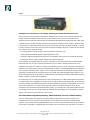
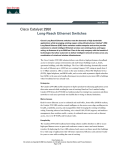
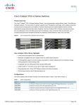
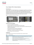
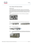
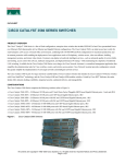
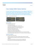
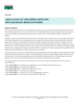
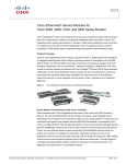
Data Sheet
Cisco Catalyst 3550 Series
Intelligent Ethernet Switches for Metro Access
Product Overview
The Cisco Catalyst® 3550 Series Intelligent
Ethernet switches is a line of powerful,
fixed-configuration multilayer switches that
extend intelligence to the metro access edge,
• Cisco Catalyst 3550-24-FX Switch—
24 100FX multimode fiber ports and
2 GBIC-based Gigabit Ethernet
ports; 1 RU
• Cisco Catalyst 3550-48 Switch—
enabling service breadth, availability,
48 10/100 ports and 2 GBIC-based
security, and manageability. Key components
Gigabit Ethernet ports; 1 RU
of the Cisco Metro Ethernet Switching
• Cisco Catalyst 3550-12G Switch—
portfolio, these switches are ideal for service
10 GBIC-based Gigabit Ethernet ports
providers looking to deliver profitable
and 2 10/100/1000BaseT ports; 1.5 RU
Ethernet services while minimizing total
• Cisco Catalyst 3550-12T Switch—
cost of ownership. With a range of Fast
10 10/100/1000BaseT ports and
Ethernet, Gigabit Ethernet, DC power, and
2 GBIC-based Gigabit Ethernet
fiber configurations, the Cisco Catalyst
ports; 1.5 RU
3550 Series is the ideal metro access switch
for enterprise and small and medium-sized
business markets. Featuring 802.1Q
tunneling, high-performance IP routing,
and subsecond Spanning-Tree Protocol
(STP) convergence, this line of powerful,
yet cost-effective, fixed-configuration
switches enable a variety of metro services,
such as transparent LAN services and
business-class Internet access.
The built-in Gigabit Ethernet ports
accommodate a range of GBIC transceivers,
including the Cisco Course Wave Division
Multiplexing (CWDM) GBIC Solution,
GigaStack® GBIC, 1000BaseT,
1000BaseSX, 1000BaseLX/LH, and
1000BaseZX GBICs. High levels of
resiliency can also be implemented by
deploying dual redundant Gigabit Ethernet
uplinks, UplinkFast and Per-VLAN
The Cisco Catalyst 3550 Series Intelligent
Spanning Tree Plus (PVST+) for uplink load
Ethernet switches include the following
balancing. This Gigabit Ethernet flexibility
configurations:
makes the Cisco Catalyst 3550 Series
• Cisco Catalyst 3550-24 Switch—
switches an ideal metro access edge
24 10/100 ports and 2 Gigabit Interface
complement to the Cisco 7600 Series
Converter (GBIC)-based Gigabit
Internet Router and Cisco Catalyst 6500
Ethernet ports; 1 rack unit (RU)
Series of metro Ethernet switches.
• Cisco Catalyst 3550-24-DC Switch—
24 10/100 ports and 2 gigabit interface
converter (GBIC)-based Gigabit
Ethernet ports; 1 RU DC-powered
Cisco Systems, Inc.
All contents are Copyright © 1992–2002 Cisco Systems, Inc. All rights reserved. Important Notices and Privacy Statement.
Page 1 of 20
Included with the Cisco Catalyst 3550-24, 3550-24-DC, 3550-24-FX and 3550-48 are the Standard Multilayer
Software Image (SMI) or the Enhanced Multilayer Software Image (EMI). The SMI feature set includes advanced
QoS, rate-limiting, access control lists (ACLs), and basic state and RIP routing functionality. The EMI provides a
richer set of features including advanced hardware-based IP unicast and multicast routing and the Web Cache
Communication Protocol (WCCP). After initial deployment, the Enhanced Multilayer Software Image Upgrade Kit
gives users the flexibility to upgrade to the EMI. The Cisco Catalyst 3550-12T and 3550-12G are only available with
the EMI.
Figure 1
Cisco Catalyst 3550-24 Intelligent Ethernet Switch
Figure 2
Cisco Catalyst 3550-24-DC Intelligent Ethernet Switch
Figure 3
Cisco Catalyst 3550-24-FX Intelligent Ethernet Switch
Figure 4
Cisco Catalyst 3550-48 Intelligent Ethernet Switch
Cisco Systems, Inc.
All contents are Copyright © 1992–2002 Cisco Systems, Inc. All rights reserved. Important Notices and Privacy Statement.
Page 2 of 20
Figure 5
Cisco Catalyst 3550-12G and 3550-12T Intelligent Ethernet Switches
Intelligence at the Metro Access Edge: Enabling Profitable Ethernet Services
Service providers are facing significant challenges in meeting the service needs of their enterprise and small and
medium-sized business (SMB) market customers. As they continue to put more and more mission-critical
applications on their networks, these customers are demanding high bandwidth at speeds greater than T1/E1 and at
competitive prices. Enterprise and SMB customers have experienced the speed and cost benefits of Ethernet in their
LANs and want to extend these benefits into the wide-area and metro-area networks (WAN and MAN). However,
in today’s economic environment, service providers face several challenges as they look to meet the service needs of
their customers. Such challenges include:
• Providing profitable new services while reducing operational and capital costs
• Meeting variable bandwidth demand at speeds greater than T1/E1
• Effectively integrating existing WAN services such as Frame Relay and Asynchronous Transfer Mode (ATM)
• Building cost-effective, highly available, scalable metro Ethernet networks
These challenges are especially evident at the metro access edge. As service providers look to provide profitable
Ethernet services such as Layer 2 virtual private networks (Layer 2 VPNs) or business Internet access, Cisco
intelligent functionality such as 802.1Q tunneling, advanced quality of service (QoS), and granular rate-limiting, is
essential in the service provider’s customer located equipment. In addition, with intelligent features such as subsecond
STP convergence and CWDM GBIC support, Cisco Catalyst 3550 Series switches provide the necessary network
availability and scalability at the access edge. With Cisco Catalyst 3550 Series Intelligent Ethernet switches, Cisco
delivers the optimal balance of performance, cost-effectiveness, and intelligence, enabling profitable Ethernet service
breadth, availability, security, and manageability.
Most important, the Cisco Catalyst 3550 Series is a key component of the Cisco Metro Ethernet Switching portfolio.
For regional metro, metro aggregation and metro access, Cisco Metro Ethernet Switching enables service providers
to deliver profitable, comprehensive Ethernet services. With the effective integration of existing WAN services, such
as Frame Relay and ATM, Cisco Metro Ethernet Switching offers an unmatched breadth of service delivery
mechanisms. With its extensive automated operations support, Cisco also helps service providers minimize total cost
of ownership for new services. Through technology leadership, financial stability, and a commitment to customer
support, Cisco ensures service success from “start-to-scale.”
Service Breadth through 802.1Q Tunneling, Advanced Quality of Service, and Rate-limiting
The Cisco Catalyst 3550, with its 802.1Q tunneling capability, enables service providers to create Layer 2
transparent LAN services (TLS) with a clear separation of their network from enterprise and SMB customer
networks. Using a 802.1Q tunneling implementation, service provider VLAN information (802.1Q tag) is added to
the customer’s original 802.1Q-tagged packets as the packets come into the service provider network. The service
Cisco Systems, Inc.
All contents are Copyright © 1992–2002 Cisco Systems, Inc. All rights reserved. Important Notices and Privacy Statement.
Page 3 of 20
provider 802.1Q tag is removed when the packets exit their network, leaving the original packets untouched. Other
Layer 2 protocols such as STP, VLAN Trunk Protocol (VTP), and Cisco Discovery Protocol will also be tunneled
through the service provider’s network. The 802.1Q tunneling feature enables service providers to use a single VLAN
(up to 4096 VLAN IDs) to support customers who have multiple VLANs. In addition, the feature preserves
customers’ original VLAN IDs and segregates traffic from different customers within the service provider
infrastructure even when those customers use the same VLAN IDs. As a result, enterprise customers subscribing to
TLS can transparently send and receive traffic from other metro sites through the service provider network as though
the sites were within the same corporate LAN.
In addition to Layer 2 VPN services, Multi-VRF CE (Virtual Routing Forwarding Customer Edge, also called
VRF-lite) and Border Gateway Protocol (BGP) on the Cisco Catalyst 3550 will enable the creation of a Layer 3 VPN
service by keeping separate routing tables for each VPN customer. Multi-VRF CE is a feature that allows a service
provider to support two or more VPNs on a single 3550 switch, where IP addresses can be overlapped among the
VPNs. Multi-VRF CE uses input interfaces to distinguish routes for different VPNs and forms virtual
packet-forwarding tables by associating one or more Layer 3 interfaces with each VRF. Interfaces in a VRF can be
either physical, such as Ethernet ports, or logical, such as VLAN SVIs, but an interface cannot belong to more than
one VRF at any time.
The Cisco Catalyst 3550 offers superior Layer 3 granular QoS features to enable service providers to provide highquality services with service-level agreements (SLAs). The QoS features ensure that network traffic is classified,
prioritized, and congestion is avoided in the most efficient manner possible. The Cisco Catalyst 3550 can classify,
reclassify, police, and mark the incoming packets before the packet is placed in the shared buffer. Packet classification
allows the network elements to discriminate between various traffic flows and enforce policies based on Layer 2 and
Layer 3 QoS fields.
To implement QoS, first, the Cisco Catalyst 3550 switches identify traffic flows, or packet groups, and classify or
reclassify these groups using either the Differentiated Services Code Point (DSCP) field or the 802.1p class-of-service
(CoS) field, or both. Classification and reclassification can be based on criteria as specific as the source/destination
IP address, source/destination Media Access Control (MAC) address, or the Layer 4 Transmission Control Protocol/
User Datagram Protocol (TCP/UDP) port. At the ingress, the Cisco Catalyst 3550 can also perform policing and
marking of the packet. To ensure proper policing and marking on a per packet basis, control plane and data plane
access control lists (ACLs) are supported on all ports.
After the packet goes through classification, policing, and marking, it is assigned to the appropriate queue before
exiting the switch. The Cisco Catalyst 3550 Series supports four egress queues per port, which allows the service
provider to be more discriminating and specific in assigning priorities for the various applications. At egress, the
switch performs scheduling and congestion control. Scheduling is an algorithm that determines the order in which
the queues are processed. The switches support Weighted Round Robin (WRR) scheduling and strict priority
queuing. The WRR queuing algorithm ensures that the lower-priority packets are not entirely starved for bandwidth
and are serviced without compromising the priority settings administered by the service provider. Strict priority
queuing ensures that the highest-priority packets will always get serviced first, ahead of all other traffic, which allows
the other three queues to be serviced using WRR scheduling. In conjunction with scheduling, the Cisco Catalyst 3550
Series Gigabit Ethernet ports support congestion control via Weighted Random Early Detection (WRED). WRED
avoids congestion by setting thresholds at which packets are dropped before congestion occurs.
Cisco Systems, Inc.
All contents are Copyright © 1992–2002 Cisco Systems, Inc. All rights reserved. Important Notices and Privacy Statement.
Page 4 of 20
The Cisco Catalyst 3550 is capable of performing rate limiting via its support of the Cisco Committed Information
Rate (CIR) functionality. Through CIR, bandwidth can be guaranteed in increments as low as 8 Kbps. Bandwidth
can be allocated based on several criteria, including MAC source address, MAC destination address, IP source
address, IP destination address, and TCP/UDP port number. Per-VLAN, per-port policing on the ingress is also
supported. Each Cisco Catalyst 3550 Series 10/100 port supports eight aggregate or individual ingress policers and
eight aggregate egress policers. Each Cisco Catalyst 3550 Series Gigabit Ethernet port supports 128 aggregate or
individual ingress policers and 8 aggregate egress policers. This gives service providers the flexibility to offer more
granular services.
In addition, the Cisco Catalyst 3550 Series also supports hardware-based high-performance IP routing, such as Open
Shortest Path First (OSPF); Interior Gateway Routing Protocol (IGRP); Enhanced IGRP (EIRGP); Border Gateway
Protocol (BGP); Routing Information Protocol (RIP) and RIP v2; Protocol-Independent Multicast (PIM); and
hardware-based IGMP snooping for multicast applications. For voice over IP (VoIP), the Cisco Catalyst 3550 Series
supports Auxiliary VLAN. Together with the superior QoS and rate-limiting features mentioned above, service
providers can build a flexible network with the Cisco Catalyst 3550 Series to provide voice, video, and high-speed
data services from a single network architecture.
Service Availability through Resiliency Enhancements and Network Redundancy
The Cisco Catalyst 3550 Series provides a rich set of resiliency enhancement features to ensure quick fail-over
recovery and create a high-availability network. The IEEE 802.1w Rapid Spanning Tree standard allows the service
provider to achieve subsecond spanning tree convergence times to maximize network stability and reliability. The
IEEE 802.1s Multiple Spanning Tree standard can be deployed in conjunction with 802.1w to improve the scalability
of the STP by grouping VLANs into spanning tree instances, as well as by providing backward compatibility to
devices running the 802.1D STP.
In addition, service providers can enable Bridge Protocol Data Unit (BPDU) guard and Spanning Tree Root Guard
(STRG) to enhance the reliability of their networks. BPDU guard allows the service provider to shut down STP
PortFast-enabled interfaces to avoid receiving BPDUs from their customers’ networks. STRG prevents customer
devices outside the service provider’s network from becoming STP root nodes.
The Cisco Catalyst 3550 Series enables the service provider to construct a highly redundant network. Per-VLAN
Spanning Tree Plus (PVST+) allows the service provider to implement Layer 2 load-sharing on redundant links,
efficiently utilizing the extra capacity inherent in a redundant design. For a Layer 3 network, Cisco Hot Standby
Router Protocol (HSRP) creates redundant fail-safe routing topologies, and equal-cost routing provides Layer 3
load-balancing and redundancy. Service providers can also utilize EtherChannel® technology to aggregate up to
16 Gbps through Gigabit EtherChannel and up to 1.6 Gbps through Fast EtherChannel. The EtherChannel
technology enhances fault tolerance and offers higher speed aggregated bandwidth between switches and to routers.
In addition to resiliency and network redundancy advantages, the Cisco Catalyst 3550 Series enables metro network
scalability at the access edge through its support of the Cisco CWDM GBIC Solution. This solution allows service
providers to scale their bandwidth without deploying additional fiber. The service provider can scale up to eight
Gigabits of bandwidth on a pair of single-mode fibers at distances up to 120 km. With the support for CWDM GBICs
on the Cisco Catalyst 3550 Series, service providers can aggregate multiple Cisco Catalyst 3550 switches to easily
upgrade network bandwidth with existing fiber infrastructure.
Cisco Systems, Inc.
All contents are Copyright © 1992–2002 Cisco Systems, Inc. All rights reserved. Important Notices and Privacy Statement.
Page 5 of 20
Metro network scalability is also enhanced by the Cisco Catalyst 3550 Series support of 4,096 VLAN IDs and 1,005
active VLANs per switch. VLAN trunks can be created from any port using the standards-based 802.1Q or the Cisco
Inter-Switch Link (ISL) VLAN trunking architecture.
Service Security through Access Control Lists and Enhanced Security Features
The Cisco Catalyst 3550 Series offers enhanced data security through the use of access control lists (ACLs). By
denying packets based on source and destination MAC addresses, IP addresses, or TCP/UDP ports, users can be
restricted from sensitive portions of the network. Also, because all ACL lookups are done in hardware, forwarding
and routing performance is not compromised when implementing ACL-based security in the network. For superior
security management, the Cisco Catalyst 3550 Series supports standard and extended ACLs on VLANs, Layer 3
interfaces, as well as Layer 2 interfaces.
Service providers can also implement higher levels of security by enabling private VLAN edge. This feature provides
security and isolation between ports on a switch, ensuring that traffic travels directly from its entry point to the
aggregation device through a virtual path and cannot be directed to a different port. Local Proxy Address Resolution
Protocol (ARP) works in conjunction with private VLAN edge to minimize broadcasts and maximize
available bandwidth.
With the Cisco Catalyst 3550 Series, service providers can implement high levels of console security. Multilevel access
security on the switch console and the Web-based management interface prevents unauthorized users from accessing
or altering switch configuration. Terminal Access Controller Access Control System (TACACS+) and Remote
Authentication Dial-In User Service (RADIUS) authentication enable centralized access control of the switch and
restricts unauthorized users from altering the configuration.
Service providers are also able to enhance their network security by adding 802.1x port-based authentication for
authenticating individual customers, DHCP Interface Tracker (Option 82) for relaying customer identification
(switch and port ID) to a DHCP server, and port security with MAC address aging for limiting the concurrent MAC
addresses allowed per port.
Service Management through IE 2100 and SNMP
The Cisco Catalyst 3550 Series provides outstanding service management capabilities via Cisco IE 2100 Series
Intelligence Engine support and SNMP. Service providers will be able to integrate the Cisco Catalyst 3550 Series
seamlessly into their operations support systems (OSSs) and enable improved flow-through provisioning.
The Cisco IE 2100 Series network device allows service providers to effectively manage a network of Cisco IOS®
Software devices, including the Cisco Catalyst 3550 Series. It is a completely self-contained unit that includes a
task-oriented Web graphic user interface (GUI), a programmable extensible markup language (XML) interface,
configuration template management, and an embedded repository. Network operators can use the Web GUI to
quickly turn existing Cisco IOS CLI configuration files into reusable templates. The Cisco IE 2100 Series integrates
easily into existing customer OSSs or business support systems (BSSs) and provisioning systems via its external
repository support and the event-based Cisco IOS XML interface that effectively “workflow-enables” Cisco
device deployment.
Service providers also can manage the Cisco Catalyst 3550 Series using Simple Network Management Protocol
(SNMP) version 2 and version 3, and the Telnet interface for comprehensive in-band management. A CLI-based
management console provides detailed out-of-band management.
Cisco Systems, Inc.
All contents are Copyright © 1992–2002 Cisco Systems, Inc. All rights reserved. Important Notices and Privacy Statement.
Page 6 of 20
A comprehensive set of Management Information Bases (MIBs) is provided for the service provider to collect traffic
information on the Cisco Catalyst 3550 Series for various billing methods.
Product Features and Benefits
Feature
Benefit
Service Breadth
Layer 2 and Layer 3 VPN services
• 802.1Q tunneling expands VLAN space by using a VLAN-in-VLAN hierarchy,
and tagging the tagged packets. The 802.1Q tunneling feature enables
service providers to use a single VLAN to support customers who have
multiple VLANs, while preserving customer VLAN IDs and segregating
traffic from different customers within the service provider infrastructure
even when they appear to be on the same VLAN.
• Multi-VRF CE (VRF-lite) forms virtual packet-forwarding tables by
associating one or more Layer 3 interfaces with each VRF, allowing the
creation of multiple Layer 3 VPNs on a single Cisco Catalyst 3550 Series.
Interfaces in a VRF could be either physical, as in an Ethernet port, or logical,
as in a VLAN switch virtual interface (SVI)—requires Enhanced Multilayer
Software Image (EMI).
Voice and video services
• Protocol-Independent Multicast (PIM) for IP multicast routing within a
network enables the network to receive the multicast feed requested and
allows switches not participating in the multicast to be pruned—support for
PIM sparse mode (PIM-SM), PIM dense mode (PIM-DM), and PIM
sparse-dense mode—requires Enhanced Multilayer Software Image (EMI).
• Distance Vector Multicast Routing Protocol (DVMRP) tunneling for
interconnecting two multicast-enabled networks across
non-multicast networks—requires Enhanced Multilayer Software
Image (EMI).
• IGMP filtering provides control of the set of multicast groups to which a user
on a switch port can belong.
• Voice VLAN (auxiliary VLAN) support for VoIP application allows the
creation of data and voice VLANs on the same physical port.
• Cisco Group Management Protocol (CGMP) server functionality enables a
switch to serve as the CGMP router for CGMP client switches—requires
Enhanced Multilayer Software Image (EMI).
• IGMP snooping allows fast client “joins” and “leaves” of multicast streams
and limits bandwidth-intensive video traffic to the requestors.
• Web Cache Communication Protocol (WCCP) enables integration of cache
engines into the network infrastructure. The cache engines transparently
store frequently accessed content and then locally fulfill successive requests
for the same content, eliminating repetitive transmissions of identical
content to web servers. Cache engines accelerate content delivery and
ensure maximum scalability and availability of content. In a service-provider
network, WCCP and cache engine solution can be deployed at the points of
presence (POPs)—requires Enhanced Multilayer Software Image (EMI).
Cisco Systems, Inc.
All contents are Copyright © 1992–2002 Cisco Systems, Inc. All rights reserved. Important Notices and Privacy Statement.
Page 7 of 20
Feature
Benefit
Advanced QoS
• 802.1p CoS and DSCP field classification via marking and reclassification on
a per-packet basis using source/destination IP address, source/destination
MAC address, or Layer 4 TCP/UDP port number.
• Cisco control-plane and data-plane QoS ACLs on all ports to ensure proper
marking on a per-packet basis.
• Four egress queues per port supported in hardware to enable differentiated
management of up to four types of traffic.
• Weighted Round Robin (WRR) scheduling to ensure differential prioritization
of packet flows by intelligently servicing the egress queues.
• Weighted Random Early Detection (WRED) on all Gigabit Ethernet ports for
avoidance of congestion at the egress queues before a disruption occurs.
• Strict priority queuing to guarantee that the highest-priority packets will
always get serviced ahead of all other traffic.
• No performance penalty for highly granular QoS functionality.
Granular rate-limiting
• Cisco Committed Information Rate (CIR) functionality allows bandwidth to
be guaranteed in increments as low as 8 Kbps.
• Rate-limiting based on source/destination IP address, source/destination
MAC address, or Layer 4 TCP/UDP information—or any combination of
these fields—using QoS ACLs (IP ACLs or MAC ACLs), class maps, policy
maps and per VLAN per port.
• Ability to easily manage data-flows asynchronously both upstream and
downstream from the end-station or on the uplink via ingress and
egress policing.
• Eight aggregate or individual ingress policers and eight aggregate egress
policers on each 10/100 port.
• 128 aggregate or individual ingress policers and eight aggregate egress
policers on each Gigabit Ethernet port.
High-performance IP routing
Except static routing, RIPv1, and
RIPv2, all other IP routing features
require the Enhanced Multilayer
Software Image (EMI)
• Cisco Express Forwarding-based routing architecture performed in
hardware to deliver extremely high-performance IP routing.
• Support for all commonly deployed and industry standard IP unicast routing
protocols (RIPv1, RIPv2, OSPF, IGRP, EIGRP) for load balancing and
constructing scalable LANs.
• Static IP routing for manually building a routing table of network
path information.
• Exterior BGP (eBGP) support to exchange route information between
routers from different autonomous systems. Interior BGP (iBGP) is
supported to exchange routes between the routers within the same
autonomous systems.
• Inter-VLAN IP routing for full Layer 3 routing between two or more VLANs.
• Equal-cost routing for load balancing and redundancy.
• Fallback bridging for forwarding of non-IP traffic between two or
more VLANs.
• Cisco HSRP to create redundant fail-safe routing topologies.
Cisco Systems, Inc.
All contents are Copyright © 1992–2002 Cisco Systems, Inc. All rights reserved. Important Notices and Privacy Statement.
Page 8 of 20
Feature
Benefit
Resiliency and reliability
• IEEE 802.1w Rapid Spanning Tree (RSTP) takes advantage of point-to-point
wiring and provides rapid convergence of the spanning tree independent of
spanning-tree timers. Reconfiguration of the spanning tree can occur in less
than one second, which is critical for metro networks carrying
mission-critical and delay-sensitive traffic such as enterprise data, voice,
and video.
• IEEE 802.1s Multiple Spanning Tree (MSTP), which uses RSTP for rapid
convergence, enables VLANs to be grouped into a spanning-tree instance,
with each instance having a spanning-tree topology independent of other
spanning-tree instances. This architecture provides for multiple forwarding
paths for data traffic, enables load balancing, and reduces the number of
spanning-tree instances required to support a large number of VLANs.
• Cisco UplinkFast/BackboneFast technologies ensure quick failover recovery,
enhancing overall network stability and reliability.
• Cisco CrossStack UplinkFast (CSUF) technology provides increased
redundancy and network resiliency through fast spanning-tree convergence
(fewer than two seconds) across a stack of switches using GigaStack GBICs
in an independent stack backplane cascaded configuration.
• Redundant stacking connections provide support for a redundant loopback
connection for top and bottom switches in an independent stack backplane
cascaded configuration.
• Bridge protocol data unit (BPDU) guard shuts down Spanning-Tree Protocol
PortFast-enabled interfaces when BPDUs are received to avoid accidental
spanning-tree topology changes.
• Spanning-tree root guard prevents edge devices outside the network
administrator’s control from becoming STP root nodes.
• Command switch redundancy enabled in the Cisco Cluster Management
Suite (CMS) Software allows customers to designate a backup command
switch that takes over cluster management functions if the primary
command switch fails.
• Unidirectional link detection (UDLD) detects and disables unidirectional
links on fiber-optic interfaces caused by incorrect fiber-optic wiring or port
faults. Aggressive UDLD allows precautionary disabling of port on
bidirectional links.
• Per-port broadcast, multicast, and unicast storm control prevents faulty
end-stations from degrading overall systems performance.
• Support for (Redundant Power System) 300 (RPS 300) that provides
superior internal power source redundancy for up to six Cisco networking
devices resulting in improved fault tolerance and network uptime.
Redundancy
• Bandwidth aggregation of up to 16 Gbps through Cisco Gigabit
EtherChannel technology and up to 1.6 Gbps through Cisco Fast
EtherChannel technology enhances fault tolerance and offers higher-speed
aggregated bandwidth between switches, to routers and individual servers.
• Supports Cisco HSRP to create redundant failsafe routing topologies.
• IEEE 802.1D Spanning Tree Protocol support for redundant backbone
connections and loop-free networks simplifies network configuration and
improves fault tolerance.
Cisco Systems, Inc.
All contents are Copyright © 1992–2002 Cisco Systems, Inc. All rights reserved. Important Notices and Privacy Statement.
Page 9 of 20
Feature
Benefit
• Per VLAN Spanning Tree Plus (PVST+) allows for Layer 2 load-sharing on
redundant links to efficiently use the extra capacity inherent in a
redundant design.
• Equal-cost routing for Layer 3 load-balancing and redundancy.
• Local Proxy ARP works in conjunction with private VLAN edge to minimize
broadcasts and maximize available bandwidth.
• VLAN Trunking Protocol (VTP) pruning limits bandwidth consumption on
VTP trunks by flooding broadcast traffic only on trunk links required to reach
the destination devices.
• Internet Group Management Protocol (IGMP) snooping provides for fast
client “joins” and “leaves” of multicast streams and limits
bandwidth-intensive video traffic to only the requestors.
• Multicast VLAN registration (MVR) continuously sends multicast streams in
a multicast VLAN while isolating the streams from subscriber VLANs for
bandwidth and security reasons.
Scalability
• The Cisco CWDM GBIC solution support allows for the scaling of bandwidth
without deploying additional fiber. It provides scalability of up to eight
Gigabits of bandwidth on a pair of single-mode fibers to reach the distances
up to 100–120 km.
• Support for up to 4,096 VLAN Ids with 1,005 active VLANs per switch; and
up to 128 spanning tree instances per switch.
• VLAN trunks can be created from any port using either standards-based
802.1Q tagging or the Cisco ISL VLAN architecture.
Network-wide security features
• IEEE 802.1x for dynamic port-based security.
• Cisco security VLAN ACLs (VACLs) on all VLANs to prevent unauthorized
data flows to be bridged within VLANs.
• Cisco standard and extended IP security Router ACLs (RACLs) for defining
security policies on routed interfaces for control plane and data plane traffic.
• Port-based ACLs for Layer 2 interfaces allows security policy to be applied
on per-Layer 2 port basis.
• Time-based ACLs allow the implementation of security settings during
specific periods of the day.
• Private VLAN edge provides security and isolation between ports on a
switch, ensuring that voice traffic travels directly from its entry point to the
aggregation device through a virtual path and cannot be directed to a
different port.
• TACACS+ and RADIUS authentication to enable centralized control of the
switch and restrict unauthorized users from altering the configuration.
• Port security secures the access to a port based on the MAC address of a
user’s device and prevents unauthorized stations from accessing the switch.
The aging feature provides the capability to limit the number of concurrent
devices per port.
• Multilevel security on console access prevents unauthorized users from
altering the switch configuration.
Cisco Systems, Inc.
All contents are Copyright © 1992–2002 Cisco Systems, Inc. All rights reserved. Important Notices and Privacy Statement.
Page 10 of 20
Feature
Benefit
• SSH and SNMPv3 provides network security by encrypting administrator
traffic during Telnet and SNMP sessions. SSH and the crypto version of
SNMPv3 require a special crypto software image due to US export
restrictions.
• The user-selectable address-learning mode simplifies configuration and
enhances security.
• DHCP Interface Tracker (Option 82) enables the DHCP relay agent (Cisco
Catalyst 3550 Series Switch) to include information about itself and the
attached client when forwarding DHCP requests from a DHCP client to a
DHCP server.
Superior manageability
• Cisco IE 2100 Series support for flow-through provisioning and integration
with OSS applications via programmable interfaces.
• Simple Network Management Protocol (SNMP) v1, v2c, and v3, and Telnet
interface support delivers comprehensive in-band management, and a
command-line interface (CLI)-based management console provides detailed
out-of-band management.
• Manageable through CiscoWorks network management software on a
per-port and per-switch basis providing a common management interface
for Cisco routers, switches, and hubs.
• Cisco IOS CLI support provides common user interface and command set
with all Cisco routers and Cisco desktop switches.
• Comprehensive MIBs provided for the service provider to collect traffic
information on Cisco Catalyst 3550 Series for various billing methods.
• Supported by the Cisco Quality Policy Manager (QPM) solution for
end-to-end QoS policies
• Support for dynamic VLAN assignment through implementation of VLAN
Membership Policy Server (VMPS) client functionality provides flexibility in
assigning ports to VLANs. Dynamic VLAN enables fast assignment of
IP address.
• Supported by the CiscoWorks 2000 LAN Management Solution.
• Supported by the Cisco Service Assurance (SA) Agent to facilitate service
level management throughout the LAN.
• Built-in Web-based Cisco Cluster Management Suite (CMS) Software
provides an easy-to-use Web-based management interface through a
standard Web browser.
• Switch Database Manager templates for access, routing, and VLAN
deployment scenarios allow the network administrator to easily
maximize memory allocation to the desired features based on
deployment-specific requirements.
• Embedded Remote Monitoring (RMON) software agent supports four
RMON groups (history, statistics, alarms, and events) for enhanced traffic
management, monitoring, and analysis.
• Support for all nine RMON groups through use of a Switch Port Analyzer
(SPAN) port, which permits traffic monitoring of a single port, a group of
ports, or the entire switch from a single network analyzer or RMON probe.
Cisco Systems, Inc.
All contents are Copyright © 1992–2002 Cisco Systems, Inc. All rights reserved. Important Notices and Privacy Statement.
Page 11 of 20
Feature
Benefit
• RSPAN (Remote SPAN) allows network administrators to remotely
monitor ports in a Layer 2 switch network from any other switch in the
same network.
• Domain Name Services (DNS) provide IP address resolution with
user-defined device names.
• Trivial File Transfer Protocol (TFTP) reduces the cost of administering
software upgrades by downloading from a centralized location.
• Network Timing Protocol (NTP) provides an accurate and consistent
timestamp to all switches within the intranet.
• Multifunction LEDs per port for port status, half-duplex/full-duplex, 10BaseT/
100BaseTX/1000BaseT indication, as well as switch-level status LEDs for
system, redundant power supply, and bandwidth utilization provide a
comprehensive and convenient visual management system.
Product Specifications
Feature
Description
Performance
• 24 Gbps switching fabric (Cisco Catalyst 3550-12G and Cisco Catalyst
3550-12T), 13.6 Gbps switching fabric (Cisco Catalyst 3550-48), 8.8 Gbps
switching fabric (Cisco Catalyst 3550-24, Cisco Catalyst 3550-24-DC, and
Cisco Catalyst 3550-24-FX)
• 12 Gbps maximum forwarding bandwidth at Layer 2 and Layer 3 (Cisco
Catalyst 3550-12G and Cisco Catalyst 3550-12T), 6.8 Gbps maximum
forwarding bandwidth at Layer 2 and Layer 3 (Cisco Catalyst 3550-48), 4.4
Gbps maximum forwarding bandwidth at Layer 2 and Layer 3 (Cisco
Catalyst 3550-24, Cisco Catalyst 3550-24-DC, and Cisco Catalyst 3550-24-FX)
• 17.0 Mpps forwarding rate for 64-byte packets (Cisco Catalyst 3550-12G and
3550-12T), 10.1 Mpps forwarding rate for 64-byte packets (Catalyst 3550-48),
6.6 Mpps forwarding rate for 64-byte packets (Cisco Catalyst 3550-24, Cisco
Catalyst 3550-24-DC, and Cisco Catalyst 3550-24-FX)
• 4 MB memory architecture shared by all ports (Cisco Catalyst 3550-12G,
3550-12T, and 3550-48), 2 MB memory architecture shared by all ports (Cisco
Catalyst 3550-24, Cisco Catalyst 3550-24-DC, and Cisco Catalyst 3550-24-FX)
• 64 MB DRAM and 16 MB Flash memory for CPU subsystem
• Configurable up to 12,000 MAC addresses (Cisco Catalyst 3550-12G and
3550-12T), configurable up to 8,000 MAC addresses (Cisco Catalyst 3550-48,
3550-24, 3550-24-DC, and Cisco Catalyst 3550-24-FX)
• Configurable up to 24,000 unicast routes (Cisco Catalyst 3550-12G and
3550-12T), Configurable up to 16,000 unicast routes (Cisco Catalyst 3550-48,
Cisco Catalyst 3550-24, Cisco Catalyst 3550-24-DC, and Cisco Catalyst
3550-24-FX)
• Configurable up to 8,000 multicast routes (Cisco Catalyst 3550-12G and
3550-12T), Configurable up to 2,000 multicast routes (Cisco Catalyst
3550-48, Catalyst 3550-24, Catalyst 3550-24-DC, and Catalyst 3550-24-FX)
Cisco Systems, Inc.
All contents are Copyright © 1992–2002 Cisco Systems, Inc. All rights reserved. Important Notices and Privacy Statement.
Page 12 of 20
Feature
Description
• Configurable Maximum Transmission Unit (MTU) of up to 2,000 Bytes for
bridging of MPLS tagged frames (Cisco Catalyst 3550-12G and 3550-12T),
Configurable Maximum Transmission Unit (MTU) of up to 1,546 Bytes for
bridging of MPLS tagged frames (Cisco Catalyst 3550-48, Cisco Catalyst
3550-24, Cisco Catalyst 3550-24-DC, and Cisco Catalyst 3550-24-FX)
Management
• BRIDGE-MIB (RFC 1493)
• CISCO-CDP-MIB
• CISCO-CLUSTER-MIB
• CISCO-CONFIG-MAN-MIB
• CISCO-FLASH-MIB
• CISCO-HSPR-EXT-MIB
• CISCO-HSRP-MIB
• CISCO-IGMP-FILTER-MIB
• CISCO-IMAGE-MIB
• CISCO-L2L3-INTERFACE-MIB
• CISCO-MAC-NOTIFICATION-MIB
• CISCO-MEMORY-POOL-MIB
• CISCO-PAGP-MIB
• CISCO-PORT-QOS-MIB
• CISCO-PROCESS-MIB
• CISCO-RTTMON-MIB (subsystems supported: sub_rtt_rmon and
sub_rtt_rmonlib)
• CISCO-STACK-MIB (only a subset of the available MIB objects are
implemented; not all objects are supported)
• CISCO-STP-EXTENSIONS-MIB
• CISCO-TCP-MIB
• CISCO-VLAN-IFTABLE-RELATIONSHIP-MIB
• CISCO-VLAN-IFINDEX-RELATIONSHIP-MIB
• CISCO-VLAN-MEMBERSHIP-MIB
• CISCO-VTP-MIB
• ENTITY-MIB
• IF-MIB
• IGMP-MIB
• IPMROUTE-MIB
• OLD-CISCO-CHASSIS-MIB
Cisco Systems, Inc.
All contents are Copyright © 1992–2002 Cisco Systems, Inc. All rights reserved. Important Notices and Privacy Statement.
Page 13 of 20
Feature
Description
• OLD-CISCO-SYSTEM-MIB
• OLD-CISCO-TS-MIB
• OSPF-MIB (RFC 1253)
• PIM MIB
• RFC1213-MIB
• RMON1-MIB (only RMON etherStats, etherHistory, alarms, and events
are supported)
• RMON2-MIB
• SNMPv2-MIB
• TCP-MIB
• UDP-MIB
Standards
• IEEE 802.1x
• IEEE 802.1w
• IEEE 802.1s
• IEEE 802.3x full duplex on 10BaseT, 100BaseTX, and 1000BaseT ports
• IEEE 802.1D Spanning-Tree Protocol
• IEEE 802.1p CoS Prioritization
• IEEE 802.1Q VLAN
• IEEE 802.3 10BaseT specification
• IEEE 802.3u 100BaseTX specification
• IEEE 802.3ab 1000BaseT specification
• IEEE 802.3z 1000BaseX specification
• 1000BaseX (GBIC)
• 1000BaseSX
• 1000BaseLX/LH
• 1000BaseZX
• 1000Base-CWDM GBIC 1470nm
• 1000Base-CWDM GBIC 1490nm
• 1000Base-CWDM GBIC 1510nm
• 1000Base-CWDM GBIC 1530nm
• 1000Base-CWDM GBIC 1550nm
• 1000Base-CWDM GBIC 1570nm
• 1000Base-CWDM GBIC 1590nm
Cisco Systems, Inc.
All contents are Copyright © 1992–2002 Cisco Systems, Inc. All rights reserved. Important Notices and Privacy Statement.
Page 14 of 20
Feature
Description
• 1000Base-CWDM GBIC 1610nm
• RMON I and II standards
• SNMPv1, SNMPv2c, AND SNMPv3
Year 2000 (Y2K) compliance
• Y2K compliant
Connectors and cabling
• 10BaseT ports: RJ-45 connectors; two-pair Category 3, 4, or 5 unshielded
twisted-pair (UTP) cabling
• 100BaseTX ports: RJ-45 connectors; two-pair Category 5 UTP cabling
• 100BaseFX ports: MT-RJ connectors, 50/125 or 62.5/125 micron multimode
fiber-optic cabling
Type of Cable
Cisco Part Number
• 1-meter, MT-RJ-to-SC multimode cable
CAB-MTRJ-SC-MM-1M
• 3-meter, MT-RJ-to-SC multimode cable
CAB-MTRJ-SC-MM-3M
• 5-meter, MT-RJ-to-SC multimode cable
CAB-MTRJ-SC-MM-5M
• 1-meter, MT-RJ-to-ST multimode cable
CAB-MTRJ-ST-MM-1M
• 3-meter, MT-RJ-to-ST multimode cable
CAB-MTRJ-ST-MM-3M
• 5-meter, MT-RJ-to-ST multimode cable
CAB-MTRJ-ST-MM-5M
• 1000BaseT ports: RJ-45; two-pair Category 5 UTP cabling
• 1000BaseT GBIC-based ports: RJ-45 connectors; two-pair Category
5 UTP cabling
• 1000BaseSX, -LX/LH, -ZX, and CWDM GBIC-based ports: SC fiber
connectors, single-mode or multimode fiber
• Cisco GigaStack GBIC ports: copper-based Cisco GigaStack cabling
• Management console port: 8-pin RJ-45 connector, RJ-45-to-RJ-45 rollover
cable with RJ-45-to-DB9 adapter for PC connections; for terminal
connections, use RJ-45-to-DB25 female data-terminal-equipment (DTE)
adapter (can be ordered separately from Cisco, part number
ACS-DSBUASYN=)
Power connectors
Customers can provide power to a switch by using either the internal power
supply or the Cisco RPS 300 Redundant Power System. The connectors are
located at the back of the switch.
Internal Power Supply Connector
• The internal power supply is an auto-ranging unit.
• The internal power supply supports input voltages between 100 and
240 VAC.
• Use the supplied AC power cord to connect the AC power connector to an
AC power outlet.
Cisco RPS Connector
Cisco Systems, Inc.
All contents are Copyright © 1992–2002 Cisco Systems, Inc. All rights reserved. Important Notices and Privacy Statement.
Page 15 of 20
Feature
Description
• The connector offers connection for an optional Cisco RPS 300 that uses AC
input and supplies DC output to the switch.
• The connector offers a 300-watt redundant power system that can support
six external network devices and provides power to one failed device at
a time.
• The connector automatically senses when the internal power supply of a
connected device fails and provides power to the failed device, preventing
loss of network traffic.
• Attach only the Cisco RPS 300 (model PWR300-AC-RPS-N1) to the
redundant-power-supply receptacle.
Indicators
• Per-port status LEDs: link integrity, disabled, activity, speed, and
full-duplex indications
• System status LEDs: system, RPS, and bandwidth utilization indications
Dimensions and weight (HxWxD)
• 2.63 x 17.5 x 15.9 in. (6.7 x 40.4 x 44.5 cm) (Cisco Catalyst 3550-12G and
3550-12T)
• 1.75 x 17.5 x 14.4 in. (4.45 x 36.6 x 44.5 cm) (Cisco Catalyst 3550-24 and Cisco
Catalyst 3550-24-DC)
• 1.75 x 17.5 x 16.3 in. (4.45 x 41.3 x 44.5 cm) (Cisco Catalyst 3550-48 and Cisco
Catalyst 3550-24-FX)
• 1.5 rack-unit (RU) high (Cisco Catalyst 3550-12G and 3550-12T)
• 1.0 RU high (Cisco Catalyst 3550-48, Cisco Catalyst 3550-24, Cisco Catalyst
3550-24-DC, and Cisco Catalyst 3550-24-FX)
• 16 lb (7.26 kg) (Cisco Catalyst 3550-12G and 3550-12T)
• 11 lb (5.0 kg) (Cisco Catalyst 3550-24 and Cisco Catalyst 3550-24-DC)
• 13 lb (5.9 kg) (Cisco Catalyst 3550-48)
• 12 lb (5.45 kg) (Cisco Catalyst 3550-24-FX)
Environmental ranges
• Operating temperature: 32 to 113 F (0 to 45 C)
• Storage temperature: –13 to 158 F (–25 to 70 C)
• Operating relative humidity: 10 to 85% (noncondensing)
• Operating altitude: Up to 10,000 ft (3049 m)
• Storage altitude: Up to 15,000 ft (4573 m)
Power requirements
• Power consumption: 190W (maximum), 650 BTUs per hour (Cisco Catalyst
3550-12G and 3550-12T); 65W (maximum), 222 BTUs per hour (Cisco
Catalyst 3550-24);110W (maximum), 375 BTUs per hour (Cisco Catalyst
3550-48); 72W (maximum), 250 BTUs per hour (Cisco Catalyst 3550-24-DC);
85W (maximum), 290 BTUs per hour (Cisco Catalyst 3550-24-FX)
• AC input voltage/frequency: 100 to 127/200 to 240 VAC (auto-ranging),
50 to 60 Hz
Cisco Systems, Inc.
All contents are Copyright © 1992–2002 Cisco Systems, Inc. All rights reserved. Important Notices and Privacy Statement.
Page 16 of 20
Feature
Description
• DC input voltages
– RPS input: +12V @ 13A (Catalyst 3550-12G, 3550-12T, and 3550-48); +12V
@ 8.3A (Catalyst 3550-24 and 3550-24-FX)
– DC input for 3550-24-DC: –36 to –72VDC @ 2A
Acoustic noise
• ISO 7770, bystander position—operating to an ambient temperature of 30
degrees Celsius:
– Catalyst 3550-12G and 3550-12T: 58 dBa
– Catalyst 3550-24 and 3550-24-DC: 48 dBa
– Catalyst 3550-48 and 3550-24-FX: 46 dBa
Mean time between failure (MTBF)
• 110,332 hours (Cisco Catalyst 3550-12G)
• 113,658 hours (Cisco Catalyst 3550-12T)
• 193,000 hours (Cisco Catalyst 3550-24)
• 163,000 hours (Cisco Catalyst 3550-48)
• 183, 000 hours (Cisco Catalyst 3550-24-DC)
• 186,000 hours (Cisco Catalyst 3550-24-FX)
Regulatory Agency Approvals
Safety certifications
•
•
•
•
•
•
UL to UL 1950, Third Edition
c-UL to CAN/CSA 22.2 No. 950-95, Third Edition
TUV/GS to EN 60950 with Amendment A1-A4 and A11
CB to IEC 60950 with all country deviations
NOM to NOM-019-SCFI
CE Marking
Electromagnetic emissions
certifications
•
•
•
•
•
•
FCC Part 15 Class A
EN 55022 Class A (CISPR 22 Class A)
VCCI Class A
AS/NZS 3548 Class A
BSMI
CE Marking
Network Equipment Building
Systems (NEBS) (for 3550-24-DC)
•
•
•
•
Bellcore
GR-1089-CORE
GR-63-CORE
SR-3580 Level 3
Warranty
• Limited lifetime warranty
Cisco Systems, Inc.
All contents are Copyright © 1992–2002 Cisco Systems, Inc. All rights reserved. Important Notices and Privacy Statement.
Page 17 of 20
Service and Support
The services and support programs described in the Table below are available as part of the Cisco Desktop Switching
Service and Support solution, and are available directly from Cisco and through resellers.
Service and Support
Features
Cisco Advanced Services
Benefits
•
Cisco Total Implementation Solutions
(TIS)—available direct from Cisco
Packaged Total Implementation
Solutions (Packaged TIS)—available
through resellers
• Project management
• Site survey, configuration
deployment
• Installation, text, and cutover
• Training
• Major moves, adds, changes
(MAC)
• Design review and product staging
• Supplements existing staff
• Ensures functionality meets
needs
• Mitigates risk
• 24x7 access to software updates
• Web access to technical
repositories
• Telephone support through the
Cisco Technical Assistance Center
• Advance replacement of hardware
parts
• Enables proactive or expedited
issue resolution
• Lowers cost of ownership by
utilizing Cisco expertise and
knowledge
• Minimizes network downtime
Cisco Technical Support Services
Cisco SMARTnet™ and SMARTnet
Onsite (OS)—available direct
from Cisco
Packaged SMARTnet—available
through resellers
Ordering Information
Model Numbers
Configuration
WS-C3550-12G
• 10 1000BaseX ports + 2 10/100/1000BaseT ports
• 1.5 rack unit (RU) stackable, multilayer Gigabit Ethernet switch
• Provides advanced IP routing
WS-C3550-12T
• 10 10/100/1000BaseT ports + 2 1000BaseX ports
• 1.5 rack unit (RU) stackable, multilayer Gigabit Ethernet switch
• Provides advanced IP routing
WS-C3550-24-SMI
•
•
•
•
24 10/100 ports + 2 1000BaseX ports
1 RU stackable, multilayer switch
Provides advanced IP routing
Standard Multilayer Software Image (SMI) installed, upgradable to advanced
IP routing
WS-C3550-24-DC-SMI
•
•
•
•
24 10/100 ports + 2 1000BaseX ports
1 RU stackable, multilayer switch; DC-Powered
Provides basic IP routing
Standard Multilayer Software Image (SMI) installed, upgradable to advanced
IP routing
Cisco Systems, Inc.
All contents are Copyright © 1992–2002 Cisco Systems, Inc. All rights reserved. Important Notices and Privacy Statement.
Page 18 of 20
Model Numbers
Configuration
WS-C3550-24-FX-SMI
•
•
•
•
24 100FX ports + 2 1000BaseX ports
1 RU stackable, multilayer switch
Provides basic IP routing
Standard Multilayer Software Image (SMI) installed, upgradable to advanced
IP routing
WS-C3550-24-EMI
•
•
•
•
24 10/100 ports + 2 1000BaseX ports
1 RU stackable, multilayer switch
Enhanced Multilayer Software Image (EMI) installed
Provides advanced IP routing
WS-C3550-48-SMI
• 48 10/100 ports + 2 1000BaseX ports
• 1 RU stackable, multilayer switch
• Standard Multilayer Software Image (SMI) installed, upgradable to advanced
IP routing
WS-C3550-48-EMI
•
•
•
•
CD-3550-EMI=
• Enhanced Multilayer Software Image (EMI) upgrade kit for standard versions of
the Cisco Catalyst 3550-24, 3550-24-DC, 3550-24-FX, and 3550-48 switches
• Provides advanced IP routing
RCKMNT-3550-1.5RU=
• Spare rack mount kit for the Cisco Catalyst 3550-12G and 3550-12T switches
RCKMNT-1RU=
• Spare rack mount kit for the Cisco Catalyst 3550-24, 3550-24-DC, 3550-24-FX, and
3550-48 switches
48 10/100 ports + 2 1000BaseX ports
1 RU stackable, multilayer switch
Enhanced Multilayer Software Image (EMI) installed
Provides advanced IP routing
For More Information on Cisco Products, Contact:
• United States and Canada: 800 553-NETS (6387)
• Europe: 32 2 778 4242
• Australia: 612 9935 4107
• Other: 408 526-7209
• World Wide Web URL: http://www.cisco.com
Cisco Systems, Inc.
All contents are Copyright © 1992–2002 Cisco Systems, Inc. All rights reserved. Important Notices and Privacy Statement.
Page 19 of 20
Corporate Headquarters
Cisco Systems, Inc.
170 West Tasman Drive
San Jose, CA 95134-1706
USA
www.cisco.com
Tel: 408 526-4000
800 553-NETS (6387)
Fax: 408 526-4100
European Headquarters
Cisco Systems International BV
Haarlerbergpark
Haarlerbergweg 13-19
1101 CH Amsterdam
The Netherlands
www-europe.cisco.com
Tel: 31 0 20 357 1000
Fax: 31 0 20 357 1100
Americas Headquarters
Cisco Systems, Inc.
170 West Tasman Drive
San Jose, CA 95134-1706
USA
www.cisco.com
Tel: 408 526-7660
Fax: 408 527-0883
Asia Pacific Headquarters
Cisco Systems, Inc.
Capital Tower
168 Robinson Road
#22-01 to #29-01
Singapore 068912
www.cisco.com
Tel: +65 317 7777
Fax: +65 317 7799
Cisco Systems has more than 200 offices in the following countries and regions. Addresses, phone numbers, and fax numbers are listed on the
Cisco Web site at www.cisco.com/go/offices
Argentina • Australia • Austria • Belgium • Brazil • Bulgaria • Canada • Chile • China PRC • Colombia • Costa Rica • Croatia
Czech Republic • Denmark • Dubai, UAE • Finland • France • Germany • Greece • Hong Kong SAR • Hungary • India • Indonesia • Ireland
Israel • Italy • Japan • Korea • Luxembourg • Malaysia • Mexico • The Netherlands • New Zealand • Norway • Peru • Philippines • Poland
Portugal • Puerto Rico • Romania • Russia • Saudi Arabia • Scotland • Singapore • Slovakia • Slovenia • South Africa • Spain • Sweden
S w i t z e r l a n d • Ta i w a n • T h a i l a n d • Tu r k e y • U k r a i n e • U n i t e d K i n g d o m • U n i t e d S t a t e s • Ve n e z u e l a • Vi e t n a m • Z i m b a b w e
All contents are Copyright © 1992–2002, Cisco Systems, Inc. All rights reserved. CCIP, the Cisco Arrow logo, the Cisco Powered Network mark, the Cisco Systems Verified logo, Cisco Unity, Follow Me Browsing, FormShare,
iQ Breakthrough, iQ Expertise, iQ FastTrack, the iQ logo, iQ Net Readiness Scorecard, Networking Academy, ScriptShare, SMARTnet, TransPath, and Voice LAN are trademarks of Cisco Systems, Inc.; Changing the
Way We Work, Live, Play, and Learn, Discover All That’s Possible, The Fastest Way to Increase Your Internet Quotient, and iQuick Study are service marks of Cisco Systems, Inc.; and Aironet, ASIST, BPX, Catalyst,
CCDA, CCDP, CCIE, CCNA, CCNP, Cisco, the Cisco Certified Internetwork Expert logo, Cisco IOS, the Cisco IOS logo, Cisco Press, Cisco Systems, Cisco Systems Capital, the Cisco Systems logo, Empowering the
Internet Generation, Enterprise/Solver, EtherChannel, EtherSwitch, Fast Step, GigaStack, Internet Quotient, IOS, IP/TV, LightStream, MGX, MICA, the Networkers logo, Network Registrar, Packet, PIX, Post-Routing,
Pre-Routing, RateMUX, Registrar, SlideCast, StrataView Plus, Stratm, SwitchProbe, TeleRouter, and VCO are registered trademarks of Cisco Systems, Inc. and/or its affiliates in the U.S. and certain other countries.
All other trademarks mentioned in this document or Web site are the property of their respective owners. The use of the word partner does not imply a partnership relationship between Cisco and any other company.
(0208R)
LW3663 1002