1
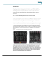
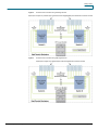
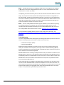
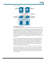
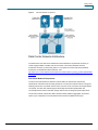
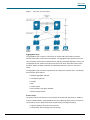
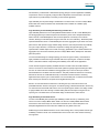
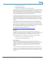
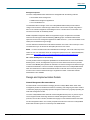
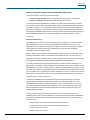
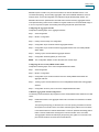
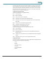
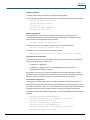
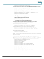
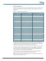
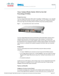
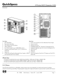
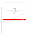
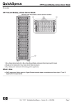
Integrating the Cisco Catalyst Blade
Switch 3020 for the HP c-Class
BladeSystem into the Cisco Data
Center Network Architecture
Design Guide
© 2008 Cisco Systems, Inc. All rights reserved. This document is Cisco Public Information.
Design Guide
Contents
Introduction ..................................................................................................................................... 3
HP c-Class BladeSystem Enclosure Overview ............................................................................. 3
Cisco Catalyst Blade Switch 3020 for HP...................................................................................... 5
Cisco Catalyst Blade Switch 3020 Features ................................................................................. 6
Spanning Tree.............................................................................................................................. 6
Traffic Monitoring.......................................................................................................................... 8
Link Aggregation Protocols........................................................................................................... 9
Data Center Network Architecture ............................................................................................... 10
Data Center Network Components............................................................................................. 10
Aggregation Layer ...................................................................................................................... 11
Access Layer.............................................................................................................................. 11
High Availability .......................................................................................................................... 12
Design Goals.............................................................................................................................. 12
High Availability .......................................................................................................................... 12
High Availability for the BladeSystem Switching Infrastructure .............................................. 13
High Availability for the Blade Servers ................................................................................... 13
Scalability ................................................................................................................................... 14
Physical Port Count ............................................................................................................... 14
Slot Count .............................................................................................................................. 15
Management .............................................................................................................................. 16
Out-of-Band Management ..................................................................................................... 16
In-Band Management ............................................................................................................ 17
Serial Console Port ................................................................................................................ 17
Management Options............................................................................................................. 18
HP c-Class BladeSystem iLO Connectivity............................................................................ 18
Design and Implementation Details............................................................................................. 18
Network Management Recommendations.................................................................................. 18
Network Topologies Using the Cisco Catalyst Blade Switch 3020 ............................................. 19
Recommended Topology....................................................................................................... 19
Alternative Topology .............................................................................................................. 22
Configuration Details .................................................................................................................. 23
VLAN Configuration ............................................................................................................... 24
RPVST+ Configuration .......................................................................................................... 24
Inter-Switch Link Configuration .............................................................................................. 24
Server-Port Configuration ...................................................................................................... 26
Server Default Gateway Configuration................................................................................... 27
RSPAN Configuration ............................................................................................................ 28
© 2008 Cisco Systems, Inc. All rights reserved. This document is Cisco Public Information.
Page 2 of 28
Design Guide
Introduction
This guide provides best design practices for deploying the Cisco® Catalyst® Blade
Switch 3020 for the HP c-Class BladeSystem enclosure within the Cisco Data Center
Networking Architecture. It describes the internal components of the blade-server
enclosure and Cisco Catalyst Blade Switch 3020 and explores different methods of
deployment.
HP c-Class BladeSystem Enclosure Overview
The HP c-Class BladeSystem enclosure represents the next generation of blade-server and bladeswitch integration. Figure 1 shows both a front and back side view of the cabinet. The c-Class
enclosure can hold up to 16 half-height servers and up to 8 switch modules. The servers are
available with either Intel or AMD processors. HP also offers full-height servers with two Intel
processors. Both support dual-core processors. The first two switch bays must contain Ethernet
switches because the onboard LAN adapters are routed to those bays. The additional six bays are
available for additional Ethernet switches, Fibre Channel switches, InfiniBand switches, or copper
or fiber pass-through modules. Each full-height server contains four Gigabit Ethernet interfaces,
two running each module in module slots 1 and 2. Full-height servers also have three mezzanine
slots for additional I/O connections such as Fibre Channel, InfiniBand, or even more Ethernet
switches.
Figure 1.
Front and Back Views of HP c-Class BladeSystem Enclosure
The HP c-Class BladeSystem backplane provides power and network connectivity to the blades.
The base I/O module slots house a pair of Cisco Catalyst Blade Switch 3020s, which provide a
highly available and multihomed environment wherein each server blade is attached through a
Gigabit Ethernet port to each Cisco Catalyst Blade Switch 3020. Two Cisco Catalyst Blade Switch
3020s within the blade enclosure connect the blade-server modules to external network devices
such as aggregation layer switches. Figures 2 and 3 show the logical connections between the
servers, the two internal blade switches, and the outside network.
© 2008 Cisco Systems, Inc. All rights reserved. This document is Cisco Public Information.
Page 3 of 28
Design Guide
Figure 2.
Enclosure Interconnections Using Full-Height Servers
Figure 3.
Enclosure Interconnections Using Half-Height Servers
© 2008 Cisco Systems, Inc. All rights reserved. This document is Cisco Public Information.
Page 4 of 28
Design Guide
Cisco Catalyst Blade Switch 3020 for HP
This section briefly describes the Cisco Catalyst Blade Switch 3020 for HP and explains how the
blade servers within the HP c-Class BladeSystem are physically connected to the switching
modules.
The Cisco Catalyst Blade Switch 3020 provides enhanced Layer 2 services (known as Layer 2+ or
Intelligent Ethernet switching) to the HP c-Class BladeSystem. The Cisco Catalyst Blade Switch
3020 enhances basic Layer 2 switching by including Cisco proprietary protocols, access control
lists (ACLs), and quality of service (QoS) based on Layer 3 information. With Simple Network
Management Protocol (SNMP), command-line interface (CLI), or HTTP management options
available and a robust set of Cisco IOS® Software switching features, the Cisco Catalyst Blade
Switch 3020 naturally integrates into the data center environment. The following features highlight
this capacity:
●
Loop protection and rapid convergence with support for Per VLAN Spanning Tree Plus
(PVST+), IEEE 802.1w, IEEE 802.1s, Bridge Protocol Data Unit (BDPU) Guard, Loop
Guard, PortFast, UplinkFast, and Unidirectional Link Detection (UDLD)
●
Advanced management protocols, including Cisco Discovery Protocol, VLAN Trunking
Protocol (VTP), and Dynamic Trunking Protocol (DTP)
●
Port Aggregation Protocol (PAgP) and Link Aggregation Control Protocol (LACP) for link
load balancing and high availability
●
Support for authentication services, including RADIUS and TACACS+ client support
●
Support for protection mechanisms, such as limiting the number of MAC addresses allowed
or shutting down the port in response to security violations
Each Ethernet switch provides eight external Ethernet ports for connecting the blade enclosure to
the external network. Four Small Form-Factor Pluggable (SFP) ports provide 1000BASE-SX
interfaces and are shared with four of the copper Gigabit Ethernet links. Two additional copper
Gigabit Ethernet ports are shared with two internal crossover interfaces connecting the pair of
switches (labeled X-Crossovers in Figures 2 and 3). All of these ports can be grouped to support
the IEEE 802.3ad LACP. Each blade server is connected to the backplane using the available
Gigabit Ethernet network interface cards (NICs). The number of NICs on each blade server varies.
Each server, whether it is full- or half-height, supports an additional Ethernet interface providing
Integrated Lights Out (iLO) support.
Note:
The iLO interface supports a management interface that resides on each server blade. For
more information about the iLO system, refer to the “Management” section of this guide.
© 2008 Cisco Systems, Inc. All rights reserved. This document is Cisco Public Information.
Page 5 of 28
Design Guide
Cisco Catalyst Blade Switch 3020 Features
This section highlights information about the protocols and features provided by the Cisco Catalyst
Blade Switch 3020 that help integrate the HP c-Class BladeSystem enclosure into the Cisco Data
Center Network Architecture.
Spanning Tree
The Cisco Catalyst Blade Switch 3020 supports different versions of the Spanning Tree Protocol
and associated features, including the following:
●
Rapid Spanning Tree Protocol (RSTP), based on IEEE 802.1w
●
Multiple Spanning Tree (MST), based on IEEE 802.1s (and includes IEEE 802.1w support)
●
PVST+
●
Rapid PVST+ (RPVST+)
●
Loop Guard
●
UDLD
●
BPDU Guard
●
PortFast
●
UplinkFast (Cisco proprietary enhancement for IEEE 802.1d deployments)
●
BackboneFast (Cisco proprietary enhancement for IEEE 802.1d deployments)
The IEEE 802.1w protocol is the standard for rapid spanning tree convergence, whereas IEEE
802.1s is the standard for multiple spanning-tree instances. Support for these protocols is essential
in a server-farm environment for allowing rapid Layer 2 convergence after a failure occurs in the
primary path. The primary benefits of IEEE 802.1w include the following:
●
The spanning-tree topology converges quickly after a switch or link failure.
●
Convergence is accelerated by a handshake, known as the proposal agreement
mechanism.
Note:
The user need not enable PortFast, BackboneFast, or UplinkFast if running RSTP.
In terms of convergence, Spanning Tree Protocol algorithms based on IEEE 802.1w are much
faster than the traditional Spanning Tree Protocol IEEE 802.1d algorithms. The proposal
agreement mechanism allows the Cisco Catalyst Blade Switch 3020 to decide new port roles by
exchanging proposals with its neighbors.
With IEEE 802.1w, as with other versions of the Spanning Tree Protocol, BPDUs are sent by
default every 2 seconds (called the hello time). If three BPDUs are missed, Spanning Tree Protocol
recalculates the topology, a process that takes less than 1 second for IEEE 802.1w.
Because the data center is made of point-to-point links, the only failures are physical failures of the
networking devices or links. The IEEE 802.1w protocol can actively confirm that a port can safely
transition to forwarding without relying on any timer configuration, meaning that the actual
convergence time is less than 1 second.
© 2008 Cisco Systems, Inc. All rights reserved. This document is Cisco Public Information.
Page 6 of 28
Design Guide
A scenario wherein BPDUs are lost may be caused by unidirectional links, which can cause Layer
2 loops. To prevent this problem, use Loop Guard and UDLD. Loop Guard prevents a port from
forwarding as a result of missed BPDUs, which might cause a Layer 2 loop that could bring down
the network.
UDLD allows devices to monitor the physical configuration of fiberoptic or copper Ethernet cables
and detect when a unidirectional link exists. When a unidirectional link is detected, UDLD shuts
down the affected port and generates an alert. BPDU Guard prevents a port from being active in a
spanning-tree topology as a result of an attack or a misconfigured device connected to the switch
port. The port that sees unexpected BPDUs is automatically disabled and must then be manually
enabled, giving the network administrator full control over port and switch behavior.
The Cisco Catalyst Blade Switch 3020 supports Per VLAN Spanning Tree (PVST) and a maximum
of 128 spanning- tree instances. RPVST+ is a combination of Cisco PVST Plus (PVST+) and
RSTP, provides the flexibility of one spanning-tree instance per VLAN and the fast convergence
benefits of IEEE 802.1w. MST allows the switch to map several VLANs to one spanning-tree
instance, reducing the total number of spanning-tree topologies the switch processor must manage.
A maximum of 16 MST instances is supported. In addition, MST uses IEEE 802.1w for rapid
convergence. MST and RPVST+ create a more predictable and resilient spanning-tree topology,
while providing downward compatibility for integration with devices that use IEEE 802.1d and
PVST+ protocols.
Figure 4 illustrates an example of Spanning Tree Protocol when using two switches in the
crossover configuration. Each blade switch is dual homed to each aggregation switch through a 2port Cisco EtherChannel interface. In this figure the blocked links are indicated in red. In this
example, only four of the eight uplinks from each blade switch are used. The network designer can
make those EtherChannel uplinks more robust (up to four 4 ports each), or use them to connect
other devices such as intrusion detection systems (IDSs) or standalone servers.
Figure 4.
Spanning-Tree Example with the HP c-Class Enclosure and Cisco Catalyst Blade Switch 3020s
© 2008 Cisco Systems, Inc. All rights reserved. This document is Cisco Public Information.
Page 7 of 28
Design Guide
Note:
The IEEE 802.1w protocol is enabled by default when running spanning tree in RPVST+
or MST mode on the Cisco Catalyst Blade Switch 3020. The Cisco Catalyst Blade Switch 3020
enables PVST+ for VLAN 1 by default.
The Spanning Tree Protocol uses the path cost value to determine the shortest distance to the root
bridge. The port path cost value represents the media speed of the link and is configurable on a
per-interface basis, including Cisco EtherChannel interfaces. To allow for more granular Spanning
Tree Protocol calculations, enable the use of a 32-bit value instead of the default 16-bit value. The
longer path cost better reflects changes in the speed of channels and allows the Spanning Tree
Protocol to optimize the network in the presence of loops.
Note:
The Cisco Catalyst Blade Switch 3020 supports IEEE 802.1t, which allows for spanning-
tree calculations based on a 32-bit path cost value instead of the default 16 bits. For more
information about the standards supported by the Cisco Catalyst Blade Switch 3020, refer to the
Cisco Catalyst Blade Switch 3020 Overview document: http://www.cisco.com/go/bladeswitch.
For more information regarding spanning tree and Layer 2 design in the data center, visit:
http://www.cisco.com/en/US/solutions/ns340/ns517/ns224/ns304/net_design_guidance0900aecd80
0e4d2e.pdf.
Traffic Monitoring
The Cisco Catalyst Blade Switch 3020 supports the following traffic-monitoring features, which are
useful for monitoring blade-enclosure traffic in data center environments:
●
Switched Port Analyzer (SPAN)
●
Remote SPAN (RSPAN)
SPAN mirrors traffic transmitted or received on source ports or source VLANs to another local
switch port. This traffic can be analyzed by connecting a switch or Remote Monitoring (RMON)
probe to the destination port of the mirrored traffic. Only traffic that enters or leaves source ports or
source VLANs can be monitored using SPAN.
RSPAN facilitates remote monitoring of multiple switches across your network. The traffic for each
RSPAN session is carried over a user-specified VLAN that is dedicated to that RSPAN session for
all participating switches. The SPAN traffic from the source ports or source VLANs is copied to the
RSPAN VLAN. This mirrored traffic is then forwarded over trunk ports to any destination session
that is monitoring the RSPAN VLAN.
Figure 5 illustrates the use of RSPAN in a dual-blade switch environment. Here the internal crossconnects can allow the RSPAN traffic to traverse the backplane from one switch to the other. The
second switch can either send the SPAN traffic out an uplink port to a local IDS device or pass it up
the EtherChannel uplink to the aggregation switch above. Because RSPAN uses its own unique
VLAN, it can use ports that may be blocked by other data VLANs.
© 2008 Cisco Systems, Inc. All rights reserved. This document is Cisco Public Information.
Page 8 of 28
Design Guide
Figure 5.
RSPAN Example
Link Aggregation Protocols
Cisco Fast EtherChannel interfaces and Gigabit EtherChannel interfaces are logically bundled, and
they provide link redundancy and scalable bandwidth between network devices. PAgP and LACP
help automatically create these channels by exchanging packets between Ethernet interfaces and
negotiating a logical connection. PAgP is a Cisco proprietary protocol that can be run only on Cisco
switches or on switches manufactured by vendors that are licensed to support PAgP. LACP is a
standard protocol that allows Cisco switches to manage Ethernet channels between any switches
that conform to the IEEE 802.3ad protocol. Because the Cisco Catalyst Blade Switch 3020
supports both protocols, you can use either IEEE 802.3ad or PAgP to form port channels between
Cisco switches.
For both of these protocols, a switch learns the identity of partners capable of supporting either
PAgP or LACP and identifies the capabilities of each interface. The switch dynamically groups
similarly configured interfaces into a single, logical link, called a channel or aggregate port. The
interface grouping is based on hardware, administrative, and port parameter attributes. For
example, PAgP groups interface with the same speed, duplex mode, native VLAN, VLAN range,
trunking status, and trunking type. After grouping the links into a port channel, PAgP adds the
group to the spanning tree as a single switch port.
In Figure 6, each blade switch uses an alternative configuration. The switch is no longer dual
homed; instead all the ports are put into a single Cisco EtherChannel uplink to the aggregation
switch above. This single EtherChannel uplink can use up to the full 8 ports, providing a 2-to-1
cable reduction from the servers. In this configuration, the Spanning Tree Protocol may not be
needed because there is no loop in the network if the interconnect ports between the two blade
switches are disabled.
© 2008 Cisco Systems, Inc. All rights reserved. This document is Cisco Public Information.
Page 9 of 28
Design Guide
Figure 6.
Alternative Network Configuration
Data Center Network Architecture
The architecture of the data center infrastructure must address the requirements necessary to
create a highly available, scalable, and secure network. This section describes the basic
architecture necessary to meet these goals. It is a synopsis of the Cisco Data Center Network
Architecture; for details about this architecture, visit:
http://www.cisco.com/en/US/solutions/ns340/ns517/ns224/ns304/net_design_guidance0900aecd80
0e4d2e.pdf.
Data Center Network Components
The terms front-end network and back-end network define the devices that comprise the
infrastructure of the data center and their general role. The front-end network is the IP routing and
switching environment. It provides client-to-server, server-to-server, and server-to-storage network
connectivity. The back-end network supports the storage-area-network (SAN) fabric and
connectivity between servers and other storage devices such as storage arrays and tape drives.
The front-end network contains two distinct functional areas called the aggregation and access
layers. Figure 7 depicts the front-end network and the services available at each layer.
© 2008 Cisco Systems, Inc. All rights reserved. This document is Cisco Public Information.
Page 10 of 28
Design Guide
Figure 7.
Data Center Front-End Network
Aggregation Layer
The aggregation layer is a point of convergence for network traffic that provides connectivity
between server farms and the rest of the enterprise. The aggregation layer supports Layer 2 and
Layer 3 functions and presents an ideal location for deploying centralized application, security, and
management services. Shared across the access layer server farms, these data center services
provide an efficient, scalable, predictable, and deterministic behavior common to server-farm
needs.
The aggregation layer provides a comprehensive set of features for the data center. The following
devices support these features:
●
Multilayer aggregation switches
●
Load-balancing devices
●
Firewalls
●
IDSs
●
Content engines
●
Secure Sockets Layer (SSL) offloaders
●
Network-analysis devices
Access Layer
The primary role of the access layer is to provide the server farms with port density. In addition, it
must be a flexible, efficient, and predictable environment supporting client-to-server and server-toserver traffic. A Layer 2 domain meets these requirements by providing the following:
●
Adjacency between servers and service devices
●
A deterministic, fast-converging, loop-free topology
© 2008 Cisco Systems, Inc. All rights reserved. This document is Cisco Public Information.
Page 11 of 28
Design Guide
Layer 2 adjacency in the server farm allows for the deployment of servers or clusters that require
the exchange of information done at Layer 2 only. It also readily supports access to network
services in the aggregation layer such as load balancers and firewalls, enabling an efficient use of
shared, centralized network services by the server farms. In contrast, if services are deployed at
each access switch, the benefit of those services is limited to the servers directly attached to the
switch. It is easier to insert new servers into the access layer when the aggregation layer is
responsible for data center services, and the Layer 2 environment provides the flexibility to scale
the number of ports -- another benefit provided in a Layer 2 access layer.
The access layer must provide a deterministic environment to help ensure a stable Layer 2 domain.
A predictable access layer allows the spanning tree to converge and recover quickly during failover
and fallback scenarios.
High Availability
High availability in the data center is a goal that must be achieved systematically. A highly available
environment is attainable by addressing each layer of the data center and each of the devices that
comprise that particular data center layer. Network and software features help achieve high
availability, as well as physical redundancy of links and devices.
The aggregation and access layers use redundant devices and links to help ensure no single point
of failure occurs. The Layer 2 and Layer 3 features supported by these switches also create a
highly available infrastructure. Spanning Tree Protocol support on both the aggregation and access
switches creates a deterministic topology that converges quickly. Logical redundancy or fault
tolerance may be achieved with Layer 3 technologies such as Hot Standby Router Protocol (HSRP)
or Virtual Router Redundancy Protocol (VRRP). These protocols allow for virtualization of the
gateways for servers or clients across the physical routing devices in the network. This
virtualization mitigates the effect of a routing-device failure on the availability of data center
services. Load-balancing services deployed in the aggregation layer allow the network to monitor
server health and application availability. These devices and features combined produce a more
resilient application environment.
Dual homing a server in relation to separate access layer switches is another method to achieve a
higher level of availability in the data center. NIC teaming removes the possibility of a single NIC
failure isolating the server. It requires the server to have two separate NICs that support teaming
software. Typically, teaming software detects failures over an external network probe between
members of the team by monitoring the local status of each NIC in the team. The combination of
dual-homed servers and a network load balancer provides an even greater level of availability for
the server and the applications it supports.
Design Goals
This section describes the design goals for deploying blade servers and the functions that the
Cisco Catalyst Blade Switch 3020 supports in data centers. It discusses high availability, scalability,
and management.
High Availability
Data centers are the repository of critical business applications that support the continual operation
of an enterprise. These applications must be accessible throughout the working day during peak
times, and some on a 24-hour basis. The infrastructure of the data center, network devices, and
servers must address these diverse requirements. The network infrastructure provides device and
© 2008 Cisco Systems, Inc. All rights reserved. This document is Cisco Public Information.
Page 12 of 28
Design Guide
link redundancy combined with a deterministic topology design to achieve application-availability
requirements. Servers are typically configured with multiple NICs and dual homed to the access
layer switches to provide backup connectivity to the business application.
High availability is an important design consideration in the data center. The Cisco Catalyst Blade
Switch 3020 has numerous features and characteristics that contribute to a reliable, highly
available network.
High Availability for the BladeSystem Switching Infrastructure
High availability between the Cisco Catalyst Blade Switch 3020s in the HP c-Class BladeSystem
and the aggregation layer switches requires link redundancy. Each Cisco Catalyst Blade Switch
3020 in the HP c-Class BladeSystem uses four SFP uplinks for connectivity to the external
network, allowing for redundant paths using two links each for more redundancy. Redundant paths
implemented between the HP c-Class BladeSystem and each aggregation layer switch when each
path uses two links provide a highly resilient design. However, this setup introduces the possibility
of Layer 2 loops; therefore, a mechanism is required to manage the physical topology. The
implementation of RSTP helps ensure a fast-converging, predictable Layer 2 domain between the
aggregation layer and access switches (the Cisco Catalyst Blade Switch 3020s) when redundant
paths are present.
The recommended design is a triangle topology (as shown in Figure 4 earlier), which delivers a
highly available environment through redundant links and a spanning tree. It allows for multiple
switch or link failures without compromising the availability of the data center applications.
These channels support the publicly available subnets in the data center and traffic between
servers. The server-to-server traffic that uses these uplinks is logically segmented through VLANs
and can use network services available in the aggregation layer. There is also a port channel
defined between the two blade-enclosure switches. This path provides intraenclosure connectivity
between the servers for VLANs defined locally on the blade-enclosure switches. Clustering
applications that require Layer 2 communication can use this traffic path, as well as mirrored traffic.
Each of these port channels is composed of two Gigabit Ethernet ports.
RPVST+ is recommended as the method for controlling the Layer 2 domain because of its
predictable behavior and fast convergence. A meshed topology combined with RPVST+ allows only
one active link from each blade switch to the root of the spanning-tree domain. This design creates
a highly available server farm through controlled traffic paths and the rapid convergence of the
spanning tree. The details of the recommended design are discussed in a later section.
High Availability for the Blade Servers
The HP c-Class BladeSystem provides high availability to blade servers by multihoming each
server to the Cisco Catalyst Blade Switch 3020s. The two Cisco Catalyst Blade Switch 3020s
housed in the interconnect bays are connected to the blade server over the backplane. Four
backplane Gigabit Ethernet connections are available to every blade-server slot.
Multihoming the server blades allows the use of a NIC teaming driver, which provides another highavailability mechanism to fail over and load balance at the server level. Three modes of teaming
are supported:
© 2008 Cisco Systems, Inc. All rights reserved. This document is Cisco Public Information.
Page 13 of 28
Design Guide
●
Network Fault Tolerance (NFT)
●
Transmit Load Balancing (TLB)
●
Switch Assisted Load Balancing (server load balancing [SLB])
NFT teaming creates a virtual interface by grouping the blade-server network adapters into a team.
One adapter is the primary active interface and all other adapters are in a standby state. The virtual
adapter uses a single MAC address and a single Layer 3 address. NFT provides adapter fault
tolerance by monitoring the state of each team member’s network connection. The standby NICs
become active only if the primary NIC loses connectivity to the network.
TLB teaming supports adapter fault tolerance (NFT) and adds more functions in the server for load
balancing egress (transmit) traffic across the team. Note that a TLB team uses only one NIC to
receive traffic. The load-balancing algorithm is based on either the destination MAC or IP address.
This teaming method provides better use of the bandwidth available for egress traffic in the network
than NFT.
SLB teaming extends the functions of TLB by allowing the team to receive load-balanced traffic
from the network. This reception requires that the switch can load balance the traffic across the
ports connected to the server NIC team. The Cisco Catalyst Blade Switch 3020 supports the IEEE
802.3ad standard and Gigabit Ethernet port channels. SLB teaming can only be used on full-height
servers, because it requires that both NICS go to the same upstream switch.
For more information about NIC teaming, please visit:
http://h18000.www1.hp.com/products/servers/networking/whitepapers.html.
Scalability
The capability of the data center to adapt to increased demands without compromising its
availability is a crucial design consideration. The aggregation layer infrastructure and the services it
provides must accommodate future growth in the number of servers or subnets it supports.
When deploying blade servers in the data center, two primary factors need to be considered:
●
Number of physical ports in the aggregation and access layers
●
Number of slots in the aggregation layer switches
Physical Port Count
The introduction of blade systems into the data center requires greater port density at the
aggregation layer. Blade systems, deployed with internal switches, provide their own access layer.
The cabling and maximum number of servers per enclosure are predetermined. Scaling the
aggregation layer ports to accommodate the blade-system uplinks is an area that requires
attention.
It is important to remember that aggregation switches provide data center services such as load
balancing, security, and network analysis that may require dedicated ports for appliances or slots
for integrated services. This situation directly affects the number of ports available for access layer
connectivity.
© 2008 Cisco Systems, Inc. All rights reserved. This document is Cisco Public Information.
Page 14 of 28
Design Guide
Slot Count
The data center infrastructure must be flexible enough to allow growth in both server capacity and
service performance. Connecting a blade system directly into the aggregation layer places more
significance on the number of slots available to accommodate blade-system uplinks and integrated
services.
Traditionally, the access layer provides the port density necessary to allow the physical growth of
server farms. Modular access layer switches offer connectivity to densely packed server farms over
a few uplinks. The aggregation layer switches support a limited number of uplinks from the access
layer. With this model, the number of servers supported per uplink is high.
Blade systems use more aggregation layer resources per server than this traditional deployment
model. Each uplink from a blade enclosure provides connectivity to a maximum of 16 servers. The
aggregation layer must be flexible enough to manage the increased demand for ports and slots in
this blade server-system environment.
To scale the server farm, use an aggregation layer switch that provides an ample number of slots
for line cards or service-module expansion.
In addition, consider using the following two options (which are not mutually exclusive):
●
Deploying service switches in the aggregation layer (as depicted in Figure 8)
●
Using a data center core to accommodate multiple aggregation layer modules
Service switches are deployed in the aggregation layer to host integrated data center services such
as load balancing, intrusion detection, and network analysis. Relocating these services to a
separate switch frees ports and slots in the aggregation layer switches. This design allows the
aggregation switches to commit more slots and, ultimately, more ports to the Layer 2 connectivity of
the server farms. Figure 8 depicts deployment of a service switch.
Figure 8.
Data Center Scaling with Service Switches
© 2008 Cisco Systems, Inc. All rights reserved. This document is Cisco Public Information.
Page 15 of 28
Design Guide
The data center core is a mechanism to replicate and horizontally scale the data center
environment. In the recommended design the aggregation and access layers are regarded as a
module that can be duplicated to extend the enterprise. Each data center module provides its own
network services locally in the aggregation switches. This approach allows the network
administrator to determine the limits of each data center module and replicate as necessary.
Figure 9 depicts the design of the data center core. The aggregation switches for each data center
module are attached at Layer 3 to the core. In addition, the aggregation switches house the service
modules required to support the server farms.
Figure 9.
Design of Data Center Core
Management
The Cisco Catalyst Blade Switch 3020 is accessible for management and configuration by any of
the following traffic paths:
●
Out-of-band (OOB) management
●
In-band management
●
Serial console port
These traffic paths provide three different management options for network administration and
support different user and application interfaces to the Cisco Catalyst Blade Switch 3020. The
remote management of the blade servers within the HP c-Class BladeSystem is critical to an
efficient and scalable data center. This section discusses these topics, as well as the iLO
connectivity options provided using the enclosure to the blade servers.
Out-of-Band Management
OOB management is the practice of dedicating an interface on the managed device for carrying
management traffic. It is also the recommended management method for blade systems. OOB
management isolates the management and data traffic and provides a more secure environment.
© 2008 Cisco Systems, Inc. All rights reserved. This document is Cisco Public Information.
Page 16 of 28
Design Guide
The Cisco Catalyst Blade Switch 3020 contains an additional Fast Ethernet port, which connects to
the HP c-Class BladeSystem Onboard Administrator, providing OOB management using the insight
manager interface. The user may also use this path to access the CLI functions of the switch,
transfer SNMP information, and upload software images and configuration files. This path is
independent of the switch fabric. This Fast Ethernet port defaults to a Dynamic Host Configuration
Protocol (DHCP) client from a DHCP server either as part of the Onboard Administrator or external
on the network attached to the enclosure. The user can also set a static IP address for the Fast
Ethernet port.
The Cisco Catalyst Blade Switch 3020 supports multiple switched virtual interfaces (SVIs) to be
active at the same time; however, it does not perform any routing functions between SVIs. By
default, the SVI is created as VLAN 1 and enabled during the setup phase of the installation. The
VLAN is often referred to as the “management VLAN”. Cisco recommends that the user change the
management VLAN to something other than VLAN 1. Therefore, it is important to create an SVI
with another VLAN and allow this VLAN on the external front-panel ports. In addition, you can
manage the switch using the Fa0 port using the Onboard Administrator on the back of the
enclosure.
By default, the Cisco Catalyst Blade Switch 3020 provides no routing functions and can have only
one default gateway defined. Even though the Fa0 interface is called “routed”, it cannot route user
traffic. Therefore, if you enable multiple SVIs or enable the Fast Ethernet port, you will not be able
to access all these interfaces from other subnets. The recent migration (12.2(22)SE) of the Cisco
Catalyst Blade Switch 3020 from the LANBase image to IP Base provides basic Layer 3 routing
(RIP and Static Routing and EIRGP Stub).
For best practices in selecting the management VLAN, please visit:
http://www.cisco.com/en/US/products/hw/switches/ps700/products_white_paper09186a00801b49a
4.shtml.
In-Band Management
In-band management uses logical isolation to separate management traffic from data traffic. VLANs
segregate the two traffic types that are sharing the bandwidth of the uplink ports. This practice is
common in situations in which multiple applications running on the servers must be managed along
with the network infrastructure devices.
In-band management traffic uses the uplink trunk ports located on the back of the Cisco Catalyst
Blade Switch 3020s for management. Cisco recommends that the Data VLANs not be the same
VLAN as the management VLAN.
Serial Console Port
The front panel of the Cisco Catalyst Blade Switch 3020 has an RJ-45 serial port that can be used
to manage the switch through the CLI. The CLI can be accessed by connecting directly to the
console port with the serial port of a workstation or remotely by using terminal servers and IP
connectivity protocols such as Telnet.
© 2008 Cisco Systems, Inc. All rights reserved. This document is Cisco Public Information.
Page 17 of 28
Design Guide
Management Options
The Cisco Catalyst Blade Switch 3020 switch is manageable with the following methods:
●
HTTP-based device-manager GUI
●
SNMP-based management applications
●
Cisco IOS Software CLI
The embedded device manager on the Cisco Catalyst Blade Switch 3020 provides a GUI to
configure and monitor the switch through a Web browser. This scenario requires using either inband or out-of-band management and enabling the HTTP or HTTPS server on the switch. The
HTTP server and SSL are enabled by default.
SNMP-compatible management utilities are supported through a comprehensive set of MIB
extensions and through four Remote Monitoring (RMON) groups. CiscoWorks 2000 and HP
OpenView are two such management applications. SNMP Versions 1, 2, and 3 are available on the
switch (Cisco IOS Software Crypto image).
The CLI delivers the standard Cisco IOS Software interface over Telnet or the console port. Cisco
recommends that you use the Secure Shell (SSH) Protocol for CLI access.
Note:
For more information about the embedded device manager, refer to the online help on the
switch CLI. For more information about the management options for the HP c-Class BladeSystem,
please visit: http://h18004.www1.hp.com/products/blades/components/management.html.
HP c-Class BladeSystem iLO Connectivity
The iLO provides remote-management capabilities and is standard with all c-Class server blades.
Remote power, console, and diagnostics are just a few of the advanced functions iLO provides.
The HP c-Class BladeSystem provides two methods to access this management interface through
its Onboard Administrator. The iLO connection is independent of the Cisco Catalyst Blade Switch
3020. The blade-server’s Onboard Administrator located on the back of the enclosure provides
access to each of the iLO interfaces through a single Ethernet cable. A redundant Onboard
Administrator is also available.
Design and Implementation Details
Network Management Recommendations
An OOB network is recommended for managing the Cisco Catalyst Blade Switch 3020. OOB
management provides an isolated environment for monitoring and configuring the switch. Isolation
is achieved by deploying a physically separate management network or by logically separating the
traffic with management VLANs.
The Cisco Catalyst Blade Switch 3020 has 8 external Gigabit Ethernet ports; any of them may be
used to support network-monitoring devices and network-management traffic. Using secure
protocols, such as SSH or HTTPS, maintains the integrity of communications between the switch
and the management station. The console port positioned at the front of the Cisco Catalyst Blade
Switch 3020 is another option for connectivity to the OOB network.
© 2008 Cisco Systems, Inc. All rights reserved. This document is Cisco Public Information.
Page 18 of 28
Design Guide
Network Topologies Using the Cisco Catalyst Blade Switch 3020
This section discusses the following physical topologies:
●
Recommended topology: Classic V-shaped topology with Spanning Tree Protocol
●
Alternative topology: Square topology with Spanning Tree Protocol
These network designs emphasize high availability in the data center by eliminating any single
point of failure and by providing deterministic traffic patterns and predictable behavior during times
of network convergence. The configuration example included uses a pair of Cisco Catalyst 6513
Switches as the aggregation layer platform. This Layer 2/Layer 3 switching platform supports the
slot density and integrated network services required by data centers deploying blade systems. An
HP c-Class BladeSystem with two Cisco Catalyst Blade Switch 3020s composes the Layer 2
access layer.
Recommended Topology
Typical deployment in the data center uses the classic triangle topology. This deployment model
has no single point of failure. The Cisco Catalyst Blade Switch 3020s are dual homed to the
aggregation layer, providing link redundancy. The Spanning Tree Protocol manages the physical
loops created by the uplinks between the aggregation and access switches, facilitating a
predictable and fast-converging topology.
RPVST+ fulfills the high-availability requirements of this design and is the recommended mode of
spanning-tree operation. RPVST+ provides fast convergence (less than 1 second) in device or
uplink failure scenarios. In addition, RPVST+ offers enhanced Layer 2 features for the access layer
with integrated capabilities equivalent to PortFast, UplinkFast, and BackboneFast.
The connection between the two internal blade switches supports local traffic limited to the HP
BladeSystem; for example, clustering applications or management traffic such as remotely mirrored
(RSPAN) traffic. This connection does not carry a publicly accessible subnet (for example, a VLAN
that exists on the uplinks to the aggregation switches). If it did, another set of interfaces would have
to be accounted for in the Spanning Tree Protocol calculations. Therefore, to create a less-complex
Spanning Tree Protocol domain, these cross-connect interfaces are removed from the equation by
clearing the public VLANs from the links.
The HP c-Class BladeSystem server-blade NICs support the logical separation of VLANs by
trunking, allowing each NIC to accommodate the public and the private VLANs on the Cisco
Catalyst Blade Switch 3020s. In addition, full-height servers are dual homed to each of the two
Cisco Catalyst Blade Switch 3020s in the HP BladeSystem. This structural design allows for the
physical separation of public and private VLANs between two NICs homed to the same Cisco
Catalyst Blade Switch 3020.
A series of network-convergence tests was performed to verify and characterize the highavailability features of the recommended design. These tests consisted of passing traffic between
an external client device and the blade servers while monitoring packet loss. The following test
cases were used:
●
Uplink failure and recovery between switch A and the primary root
●
Uplink failure and recovery between switch B and the primary root
●
Switch A failure and recovery
●
Switch B failure and recovery
© 2008 Cisco Systems, Inc. All rights reserved. This document is Cisco Public Information.
Page 19 of 28
Design Guide
●
Primary root switch failure and recovery
●
Secondary root switch failure and recovery
These tests revealed the intricacies of fast convergence in the data center and the necessity for a
holistic approach to high availability. Test cases that did not involve the failure of the active HSRP
aggregation switch resulted in an average failover time of about 1 second. Failing the active HSRP
device requires convergence at Layer 3 and resulted in a recovery time that reflected the settings
of the HSRP timers.
It is possible to tune the HSRP timers for subsecond convergence. However, when multiple HSRP
devices are involved the recovery time is typically in the 5-second range.
In this topology, 2 to 4 Gigabit Ethernet links compose the port-channel uplinks between the access
and aggregation layers. This configuration allows a single link to fail without triggering Spanning
Tree Protocol convergence.
Note:
The default gateway for the servers is the HSRP address of the Layer 3 aggregation
switches. Failover times may be affected if the default gateway of the server is located on another
device, such as a load balancer or firewall.
The recommended topology provides a high level of availability to the blade servers except in one
failure scenario. If all the uplinks to each of the aggregation switches from a single Cisco Catalyst
Blade Switch 3020 are unavailable, the server NICs homed to that Cisco Catalyst Blade Switch
3020 are not notified by default. The blade servers are unaware of the disconnection between the
access layer switches (Cisco Catalyst Blade Switch 3020s) and the aggregation layer switches, so
they continue to forward traffic. To address this breakdown in network connectivity, use one of the
following methods:
●
Use the NIC teaming features of the ProLiant blade servers
●
Deploy the Layer 2 trunk failover feature in the Cisco Catalyst Blade Switch 3020s
In addition, the NIC teaming features of the blade servers provide redundancy at the networkadapter level. Stagger the preferred primary NICs between the two Cisco switches in the enclosure
to increase server availability. Assigning the primary NIC is a straightforward process. The NIC
teaming software provides a GUI or a small configuration file, depending on the operating system,
to construct the team. HP also offers network-aware teaming software to verify and detect network
routes. For more information about these features, visit the ProLiant Essential Intelligent Network
Pack at http://h18004.www1.hp.com/products/servers/proliantessentials/inp/index.html.
By monitoring the health of a server farm, a load balancer can bypass the network failure by
redirecting traffic to available servers, helping ensure fulfillment of end-user requests despite the
network failure.
The recommended network topology allows for traffic monitoring either locally or remotely using
SPAN. Local SPAN supports monitoring of network traffic within one switch, whereas RSPAN
allows the destination of mirrored traffic to be another switch within the data center. The source of
mirrored traffic for a SPAN or RSPAN session can be one or more ports or VLANs.
Local SPAN is readily supported by the Cisco Catalyst Blade Switch 3020 over any of the external
Gigabit Ethernet ports. This connection is an ideal location to attach an IDS or other networkanalysis device.
© 2008 Cisco Systems, Inc. All rights reserved. This document is Cisco Public Information.
Page 20 of 28
Design Guide
RSPAN requires a VLAN to carry the mirrored traffic to the remote destination switch. In the
recommended topology, the secondary aggregation switch is the RSPAN destination, where an
analysis device, such as the integrated Cisco Network Analysis Module (NAM), resides. The
RSPAN VLAN uses the uplink between the blade switch and the secondary aggregation switch.
This uplink is blocking under normal conditions for regular VLANs. As a result, bandwidth usage is
a concern only when the uplink is forwarding and sharing the path with production traffic.
Configuring the Aggregate Switches
Complete the following steps on the aggregate switches:
Step 1. VLAN configuration
Step 2. RPVST+ configuration
Step 3. Primary and secondary root configuration
Step 4. Configuration of port channels between aggregate switches
Step 5. Configuration of port channels between aggregate switches and Cisco Catalyst Blade
Switch 3020s
Step 6. Trunking of port channels between aggregate switches
Step 7. Configuration of default gateway for each VLAN
Note:
The “Configuration Details” section describes each of these steps.
Configuring the Cisco Catalyst Blade Switch 3020s
Complete the following steps on the Cisco Catalyst Blade Switch 3020s:
Step 1. VLAN configuration
Step 2. RPVST+ configuration
Step 3. Configuration of port channels between the Cisco Catalyst Blade Switch 3020 and
aggregate switches
Step 4. Trunking of port channels between the Cisco Catalyst Blade Switch 3020 and aggregate
switches
Step 5. Configuration of server ports on the Cisco Catalyst Blade Switch 3020
Additional Aggregation-Switch Configuration
The following recommendations help integrate the Cisco Catalyst Blade Switch 3020s into the data
center:
Step 1. Enable Root Guard on the aggregate-switch links connected to the switches in the blade
enclosure.
The spanning-tree topology is calculated, and one of the primary parameters involved in
this equation is the location of the root switch. Determining the position of the root switch
in the network allows the network administrator to create an optimized forwarding path for
traffic. The Root Guard feature is designed to control the location of the root switch.
The aggregation switches should employ the spanning-tree guard root command on the
port-channel interfaces connected to the blade switches.
© 2008 Cisco Systems, Inc. All rights reserved. This document is Cisco Public Information.
Page 21 of 28
Design Guide
Step 2. Allow only those VLANs that are necessary on the port channel between the aggregate
and the blade switches.
Use the switchport trunk allowed vlan vlanID command to configure the port-channel
interfaces of the aggregate switch to allow only those VLANs indicated with the vlanID
option.
Additional Cisco Catalyst Blade Switch 3020 Configuration
Step 1. Enable BPDU Guard on the internal server ports of the switch.
Use the spanning-tree bpduguard enable command to shut down a port that receives a
BPDU when it should not be participating in the spanning tree.
Step 2. Allow only those VLANs that are necessary on the port channels between the aggregate
and the blade switches.
Use the switchport trunk allowed vlan vlanID command to configure the port-channel
interfaces of the switch to allow only those VLANs indicated with the vlanID option.
Alternative Topology
An alternative topology that does not rely on the Spanning Tree Protocol to account for redundant
paths in the network (because there are none) is to have the two Cisco Catalyst Blade Switch
3020s connect directly to two aggregate switches using a port channel supporting the server-farm
VLANs. Four to 8 of the external uplinks of each Cisco Catalyst Blade Switch 3020 are channeled
and connected to one of the two aggregate switches. (The internal connections between the two
Cisco Catalyst Blade Switch 3020s complete the loop and thus would require Spanning Tree
Protocol.) Alternatively, if you enable the internal interconnects, you can user Layer 3 interconnects
between the aggregation layer switches and still maintain a loop-free environment.
This design uses the links between the two Cisco Catalyst Blade Switch 3020s as a redundant path
for blade-server traffic. The use of a longer path cost value provides for a more granular calculation
of the topology based on the available link bandwidth (refer to the “Cisco Catalyst Blade Switch
3020 Features” section). This feature is enabled with the spanning-tree pathcost method long CLI
command. RPVST+ should be used in this network design for its fast convergence and predictable
behavior.
The following convergence tests were conducted against this alternative topology:
●
Uplink failure and recovery between switch-A and the primary root
●
Uplink failure and recovery between switch B and the secondary root
●
Failure and recovery of switch A and switch B
●
Failure and recovery of the primary and secondary root switches
These tests yielded results similar to those of the recommended topology. Layer 2 convergence
occurs in approximately 1 second. As stated previously, recovery at Layer 3 depends on the HSRP
settings of the aggregate switches (refer to the “Recommended Topology” section). In our testbed,
the failure of the active HSRP device typically increased the convergence time to 5 seconds.
© 2008 Cisco Systems, Inc. All rights reserved. This document is Cisco Public Information.
Page 22 of 28
Design Guide
This design supports traffic monitoring using SPAN or RSPAN. For example, a network-analysis
device connected to the external ports on the front of the Cisco Catalyst Blade Switch 3020 may
capture locally mirrored traffic. Alternatively, RSPAN traffic can be carried on the Cisco Catalyst
Blade Switch 3020 uplinks if bandwidth usage is not a concern. For the steps to configure traffic
monitoring, refer to the “Configuration Details” section.
Configuring the Aggregate Switches
Complete the following steps on the aggregate switches:
Step 1. VLAN configuration
Step 2. RPVST+ configuration
Step 3. Primary and secondary root configuration
Step 4. Configuration of port channels between aggregate switches
Step 5. Configuration of port channels between aggregate switches and Cisco Catalyst Blade
Switch 3020s
Step 6. Trunking of port channels between aggregate switches
Step 7. Configuration of default gateway for each VLAN
Configuring the Cisco Catalyst Blade Switch 3020s
Complete the following steps on the Cisco Catalyst Blade Switch 3020s:
Step 1. VLAN configuration
Step 2. RPVST+ configuration
Step 3. Configuration of port channels between the Cisco Catalyst Blade Switch 3020s and
aggregate switches
Step 4. Trunking of port channels between the Cisco Catalyst Blade Switch 3020 and aggregate
switches
Step 5. Configuration of server ports on the Cisco Catalyst Blade Switch 3020
Configuration Details
This section describes the configuration steps required for implementing the topologies discussed
in this guide. It discusses configurations for the following:
●
VLAN
●
RPVST+
●
Inter-Switch Link (ISL)
●
Server port
●
Server default gateway
●
RSPAN
© 2008 Cisco Systems, Inc. All rights reserved. This document is Cisco Public Information.
Page 23 of 28
Design Guide
VLAN Configuration
To configure the VLANs on the switches, complete the following tasks:
Set the VTP administrative domain name and mode and create the server-farm VLANs as follows:
(config)# vtp domain <domain name>
(config)# vtp mode transparent
(config)# vlan 60
(config-vlan)# name bladeservers
(config-vlan)# state active
RPVST+ Configuration
Configure Spanning Tree Protocol to manage the physical loops in the topology. Cisco
recommended using RPVST+ for its fast-convergence characteristics. Set the Spanning Tree
Protocol mode on each aggregation switch as follows:
(config)# spanning-tree mode rapid-pvst
Configure the path cost to use 32 bits in the Spanning Tree Protocol calculations:
(config)# spanning-tree pathcost method long
Configure the primary and secondary root switches as follows:
(config)# spanning-tree vlan <vlan range> root primary | secondary
Inter-Switch Link Configuration
The topologies discussed in this guide require connectivity between the switches. The following
three types of interswitch connections exist:
●
Aggregate 1 to aggregate 2
●
Aggregate 1 or aggregate 2 to HP c-Class BladeSystem switch A or switch B
●
HP BladeSystem switch A to switch B
Each of these connections is a Layer 2 Cisco EtherChannel connection consisting of multiple
physical interfaces bound together as a channel group or port channel. These point-to-point links
between the switches should carry more than one VLAN; therefore, each is a trunk.
Port-Channel Configuration
Link Aggregate Control Protocol (LACP) is the IEEE standard for creating and managing Cisco
EtherChannel connections between switches. Each aggregate switch uses this feature to create a
port channel across the line cards. The use of multiple line cards within a single switch reduces the
possibility of the point-to-point port channel becoming a single point of failure in the network.
Configure the active LACP members on aggregate 1 to Cisco Catalyst Blade Switch 3020 switch A
as follows:
(config)# interface GigabitEthernet12/1
(config-if)# description <<** Connected to Switch-A **>>
(config-if)# channel-protocol lacp
(config-if)# channel-group 1 mode active
(config)# interface GigabitEthernet11/1
(config-if)# description <<** Connected to Switch-A **>>
(config-if)# channel-protocol lacp
© 2008 Cisco Systems, Inc. All rights reserved. This document is Cisco Public Information.
Page 24 of 28
Design Guide
(config-if)# channel-group 1 mode active
Configure the passive LACP members on Cisco Catalyst Blade Switch 3020 switch A as follows:
(config) # interface GigabitEthernet0/19
(config-if)# description <<** Connected to Aggregation-1 **>>
(config-if)# channel-group 1 mode on
(config) # interface GigabitEthernet0/20
(config-if)# description <<** Connected to Aggregation-1 **>>
(config-if)# channel-group 1 mode on
Trunking Configuration
Use the following guidelines when configuring trunks:
●
Allow only those that are necessary on the trunk.
●
Use IEEE 802.1q trunking.
●
Tag all VLANs over a trunk from the aggregation switches.
Configure trunks using the standard encapsulation method IEEE 802.1q as follows:
(config-if)# switchport trunk encapsulation dot1q
Define the VLANs permitted on a trunk as follows:
(config-if)# switchport trunk allowed vlan <VLAN IDs>
Modify the VLANs allowed on a trunk using one of the following commands:
(config-if)# switchport trunk allowed vlan add <VLAN IDs>
(config-if)# switchport trunk allowed vlan remove <VLAN IDs>
Define a port as a trunk port as follows:
(config-if)# switchport mode trunk
Note:
The autonegotiation of a trunk requires that the ports be in the same VTP domain and be
able to pass DTP frames.
To secure and enforce a spanning-tree topology, configure the Root Guard feature on the
aggregate-switch interfaces that connect to the blade switches. The following is an example of the
interface configuration between the aggregate and blade switch with Root Guard enabled:
(config)# interface GigabitEthernet12/13
(config-if)# description <text>
(config-if)# no ip address
(config-if)# switchport
(config-if)# switchport trunk encapsulation dot1q
(config-if)# switchport trunk native vlan <vlan id>
(config-if)# switchport trunk allowed vlan <vlan id>
(config-if)# switchport mode trunk
(config-if)# spanning-tree guard root
(config-if)# channel-protocol lacp
(config-if)# channel-group <group id> mode active
© 2008 Cisco Systems, Inc. All rights reserved. This document is Cisco Public Information.
Page 25 of 28
Design Guide
Server-Port Configuration
A blade server is assigned a specific port on the blade switch. This assignment is predetermined by
the physical slot the blade server occupies in the enclosure. Table 1 correlates the server and
switch ports.
Table 1.
Correlation of Server and Switch Ports
Cisco IOS Software CLI
Identifier
Port Location in the Enclosure (when
using full-height servers)
Port Location in the Enclosure (when
using half-height servers)
GigabitEthernet 0/1
Server slot 1 upper
Server slot 1
GigabitEthernet 0/2
Server slot 2 upper
Server slot 2
GigabitEthernet 0/3
Server slot 3 upper
Server slot 3
GigabitEthernet 0/4
Server slot 4 upper
Server slot 4
GigabitEthernet 0/5
Server slot 5 upper
Server slot 5
GigabitEthernet 0/6
Server slot 6 upper
Server slot 6
GigabitEthernet 0/7
Server slot 7 upper
Server slot 7
GigabitEthernet 0/8
Server slot 8 upper
Server slot 8
GigabitEthernet 0/9
Server slot 1 lower
Server slot 9
GigabitEthernet 0/10
Server slot 2 lower
Server slot 10
GigabitEthernet 0/11
Server slot 3 lower
Server slot 11
GigabitEthernet 0/12
Server slot 4 lower
Server slot 12
GigabitEthernet 0/13
Server slot 5 lower
Server slot 13
GigabitEthernet 0/14
Server slot 6 lower
Server slot 14
GigabitEthernet 0/15
Server slot 7 lower
Server slot 15
GigabitEthernet 0/16
Server slot 8 lower
Server slot 16
GigabitEthernet 0/17
Dual-media uplink port 1
Dual-media uplink port 1
GigabitEthernet 0/18
Dual-media uplink port 2
Dual-media uplink port 2
GigabitEthernet 0/19
Dual-media uplink port 3
Dual-media uplink port 3
GigabitEthernet 0/20
Dual-media uplink port 4
Dual-media uplink port 4
GigabitEthernet 0/21
RJ-45 copper gigabit-only uplink port 1
RJ-45 copper gigabit-only uplink port 1
GigabitEthernet 0/22
RJ-45 copper gigabit-only uplink port 2
RJ-45 copper gigabit-only uplink port 2
GigabitEthernet 0/23
Shared port with internal cross-connection
Shared port with internal cross-connection
GigabitEthernet 0/24
Shared port with internal cross-connection
Shared port with internal cross-connection
The server ports on the blade switch support a single VLAN access and trunk configuration mode.
The operational mode chosen should support the server NIC configuration (that is, a trunking NIC
is attached to a trunking switch port). Enable PortFast for the edge devices.
The BPDU Guard feature disables a port that receives a BPDU. This feature protects the Spanning
Tree Protocol topology by preventing the blade server from receiving BPDUs. An administrator
must manually recover a port disabled with the BPDU Guard feature. Enable the BPDU Guard
feature on all server ports that should not be receiving BPDUs.
Port Security limits the number of MAC addresses permitted to access the blade-switch port.
Configure the maximum number of MAC addresses expected on the port.
Note:
The NIC teaming driver configuration (that is, the use of a virtual MAC address) must be
considered when configuring Port Security.
© 2008 Cisco Systems, Inc. All rights reserved. This document is Cisco Public Information.
Page 26 of 28
Design Guide
interface GigabitEthernet0/1
description <<** BladeServer-1 **>>
switchport trunk encapsulation dot1q
switchport trunk allowed vlan 10,60
switchport mode trunk
switchport port-security aging time 20
switchport port-security maximum 1 vlan 10,60
no cdp enable
spanning-tree portfast trunk
spanning-tree bpduguard enable
end
Server Default Gateway Configuration
The default gateway for a server is a Layer 3 device located in the aggregation layer of the data
center. This device can be a firewall, a load balancer, or a router. Using protocols such as HSRP
protects the gateway from being a single point of failure and creates a highly available data center
network. HSRP allows the two aggregate switches to act as a single, virtual router by sharing a
common MAC and IP address between them. Define a SVI on each aggregate switch and use the
HSRP address as the default gateway of the server farm.
Configure aggregation 1 as the active HSRP router. The priority command helps to select this
router as the active router because it has a greater value.
interface Vlan10
description <<** BladeServerFarm – Active **>>
ip address 10.10.10.2 255.255.255.0
no ip redirects
no ip proxy-arp
arp timeout 200
standby 1 ip 10.10.10.1
standby 1 timers 1 3
standby 1 priority 51
standby 1 preempt delay minimum 60
standby 1 authentication <password>
end
Configure aggregation 2 as the standby HSRP router as follows:
interface Vlan10
description <<** BladeServerFarm – Standby **>>
ip address 10.10.10.3 255.255.255.0
no ip redirects
no ip proxy-arp
arp timeout 200
standby 1 ip 10.10.10.1
standby 1 timers 1 3
standby 1 priority 50
standby 1 preempt delay minimum 60
standby 1 authentication <password>
end
© 2008 Cisco Systems, Inc. All rights reserved. This document is Cisco Public Information.
Page 27 of 28
Design Guide
RSPAN Configuration
RSPAN allows for remote traffic monitoring in the data center. Define source and destination
sessions to mirror interesting traffic to a remote VLAN captured by network-analysis tools.
Configure a VLAN for RSPAN on the Cisco Catalyst Blade Switch 3020 and the aggregate switch
as follows:
(config)# vlan <vlanID>
(config-vlan)# name <vlan name>
(config-vlan)# remote-span
Create a source session as follows. This interface is the interface or VLAN that contains interesting
traffic.
(config) # monitor session <session id> source vlan <VLAN IDs>
Configure the RSPAN VLAN as the target for the mirrored traffic as
follows:
(config) # monitor session <session ID> destination remote vlan
<remote vlan ID>
Printed in USA
© 2008 Cisco Systems, Inc. All rights reserved. This document is Cisco Public Information.
C07-468192-00 04/08
Page 28 of 28