1
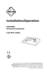
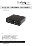
1U 17in 1080p LCD Rack Console with Front
USB Hub
RACKCONS17HD
RKCONS17HDxx
*actual product may vary from photos
DE: Bedienungsanleitung - de.startech.com
FR: Guide de l'utilisateur - fr.startech.com
ES: Guía del usuario - es.startech.com
IT: Guida per l'uso - it.startech.com
NL: Gebruiksaanwijzing - nl.startech.com
PT: Guia do usuário - pt.startech.com
For the most up-to-date information, please visit: www.startech.com
Manual Revision: 01/22/2015
FCC Compliance Statement
This equipment has been tested and found to comply with the limits for a Class B digital
device, pursuant to part 15 of the FCC Rules. These limits are designed to provide reasonable
protection against harmful interference in a residential installation. This equipment generates,
uses and can radiate radio frequency energy and, if not installed and used in accordance with
the instructions, may cause harmful interference to radio communications. However, there
is no guarantee that interference will not occur in a particular installation. If this equipment
does cause harmful interference to radio or television reception, which can be determined by
turning the equipment off and on, the user is encouraged to try to correct the interference by
one or more of the following measures:
• Reorient or relocate the receiving antenna.
• Increase the separation between the equipment and receiver.
• Connect the equipment into an outlet on a circuit different from that to which the receiver
is connected.
• Consult the dealer or an experienced radio/TV technician for help.
Use of Trademarks, Registered Trademarks, and other Protected Names and Symbols
This manual may make reference to trademarks, registered trademarks, and other
protected names and/or symbols of third-party companies not related in any way to
StarTech.com. Where they occur these references are for illustrative purposes only and do not
represent an endorsement of a product or service by StarTech.com, or an endorsement of the
product(s) to which this manual applies by the third-party company in question. Regardless
of any direct acknowledgement elsewhere in the body of this document, StarTech.com hereby
acknowledges that all trademarks, registered trademarks, service marks, and other protected
names and/or symbols contained in this manual and related documents are the property of
their respective holders.
Instruction Manual
Table of Contents
Product Overview...................................................................................1
Front View..................................................................................................................................................... 1
Rear View....................................................................................................................................................... 1
Introduction.............................................................................................2
Packaging Contents.................................................................................................................................. 2
Front Panel Controls.................................................................................................................................. 3
Installation ..............................................................................................3
Rail Installation A........................................................................................................................................ 4
Rail Installation B........................................................................................................................................ 5
Rail Installation C........................................................................................................................................ 8
Console Installation................................................................................12
PC / Server Connection............................................................................................................................ 13
Connecting to a KVM Switch................................................................................................................. 14
Operation.................................................................................................14
Specifications...........................................................................................15
Technical Support...................................................................................16
Warranty Information.............................................................................16
Instruction Manual
i
Product Overview
Front View
Top Handle
Key Lock
Menu Buttons
USB 2.0 Hub Ports
Rear View
USB Hub PC
Connection
PS/2 - USB
Selector Switch
Modular KVM DC Jack
Dock Port
Instruction Manual
PC/KVM
Connections
1
Introduction
Packaging Contents
• 1 x 1U Rack Console
• 1 x Set, Mounting Rails
• 2 x Extended Brackets
• 2 x Short Brackets
• 2 x Short Bracket Attachments
• 2 x Keys
• 1 x 6ft (1.8m) PS/2 VGA KVM Cable
• 1 x 6ft (1.8m) USB A-A Cable
• 6 x #6-32x6 Flat Screws
• 6 x M4x5 Screws
• 1 x Power Adapter
• 1 x Power Cord
• 1 x Instruction Manual
Instruction Manual
2
Front Panel Controls
The OSD (On-screen display) offers many different video, positioning and language
options. Use the table below to navigate through the menus and change settings as
needed.
Controls
Description
Soft power on/off button. Adjacent LED is lit when on.
Auto
Auto-synchronize and scale down display to any valid
factory preset timings.
Up
Press to scroll the function you want to adjust.
Down
Press to scroll the function you want to adjust.
Menu
To access the main menu. This button also acts as
the “Enter” button.
Power Indicator
GREEN
RED
RED
RED
ON
STANDBY
SUSPEND
OFF
Installation
NOTE: The Rack Console can be installed into racks where the depth measures
between 19.84 - 39.37in (504 - 1000 mm). The installation procedure will vary based on
the size of your rack:
For 24.17 – 31.5in (614 - 800mm) refer to Rail Installation A (most common).
For 19.84 – 24.17in (504 - 614mm) refer to Rail Installation B.
For 31.5 - 39.37in (800 - 1000mm) refer to Rail Installation C.
Instruction Manual
3
Rail Installation A
1. Slide the rail outward until two screws appear.
rail
two screws
2. Loosen (not remove) the seven screws shown and adjust the rail to fit your rack.
3. Secure both the front and rear brackets to your rack using the appropriate screws /
nuts for your rack (not included).
Instruction Manual
4
4. Tighten the seven screws loosened in Step 2.
5. Repeat the above steps for the other side.
Rail Installation B
1. Slide the rail outward until two screws appear.
rail
two screws
2. Remove the seven screws shown.
Instruction Manual
5
3. Remove the two original brackets from the rail.
original bracket
original bracket
4. Install the Short Bracket to the rail as shown.
Instruction Manual
6
short bracket
5. Add the Short Bracket Attachment piece to the rail and use four screws to secure
them to the rail (don’t fully tighten).
bracket attachment
short bracket
6. Secure both the front and rear brackets to your rack using the appropriate screws /
nuts for your rack (not included).
Instruction Manual
7
7. Tighten the four screws installed in Step 5.
8. Repeat the above steps on the other side.
Rail Installation C
1. Slide the rail outward until two screws appear.
rail
two screws
2. Loosen (not remove) the seven screws shown.
Instruction Manual
8
3. Remove the six screws holding the rear bracket.
4. Remove the rear bracket from the rail.
original bracket
5. Add the Extended bracket to the rail, then adjust the Extended Bracket to fit your
cabinet. Install three of the included M4x5 Screws (don’t fully tighten) to secure the
bracket in place.
Instruction Manual
9
extended bracket
6. Secure both the front and rear brackets to your rack using the appropriate screws /
nuts for your rack (not included).
7. Tighten the seven screws loosened in step 2, and the three installed in Step 5.
Instruction Manual
10
8. Repeat the above steps on the other side.
Instruction Manual
11
Console Installation
Once the rails have been installed into your rack using one of the above procedures
and all loosened screws have been tightened, use the following instructions to install
the console into the rack.
1. Push console into rails.
2. Unlock the console lid, then pull the rail-lock switches on both sides to allow the
console to slide all the way into the rack.
Lock
Unlock
rail-lock switch
Instruction Manual
12
3. Install three of the included #6-32x6 Flat Screws into the rear of the console on
both sides.
Completed installation:
PC / Server Connection
1. Turn off the PC / Server you are connecting to the console.
2. Using one of the included cable sets, connect the appropriate video (VGA / DVI)
connector to the video output of your PC / Server. Then connect either the PS/2
keyboard/mouse connectors, or use the USB interface.
3. Connect the other end of the cables to the rear of the console.
NOTE: Move the PS/2-USB Selector Switch on the rear of the console to either side to
select your desired interface
Instruction Manual
13
4. Connect the USB Hub connector using one of the included USB A-A cables to the
USB connector on your server / KVM switch to enable the front USB hub ports and
fingerprint reader (optional).
5. Connect the AC to DC power adapter to the power inlet on the console and then to
a power outlet.
Connecting to a KVM Switch
When cascading with a KVM switch, KVM Module can be used to control additional
computers from the console. The connection is exactly the same as is shown above
(see PC / Server Connection section above). The only difference is the connection
would be made to the “CONSOLE PORT” of the KVM switch instead, of a computer.
Operation
1. Once all cables are securely connected and all mounting screws are properly
tightened, grasp the Top Handle and pull the console outward, ensure the lock is in
the Unlock position and then lift upward to open.
Lock
Unlock
2. Press the Power Button on the front menu controls below the LCD panel, and power
on the connected Server or KVM switch.
3. Use the OSD controls to adjust the image as necessary – see the Front Panel
Controls section above for instruction.
Instruction Manual
14
Specifications
Display Size
17.3”
Panel Type
Active Matrix TFT LED
Maximum Screen Resolution
1920x1080 (Full HD)
Supported Platforms
USB or PS/2
Server / KVM Video Type
DVI or VGA
Response Time
2ms
Contrast Ratio
650:1
Brightness
300cd/m²
Viewing Angle
140° (H), 120° (V)
Pixel Pitch
0.198 x 0.198 mm
Keyboard/Mouse
106-key US keyboard with touchpad
Console Interface(s)
2x PS/2 (6 pin; Mini-DIN)
1x VGA (15 pin; High Density D-Sub)
1x DVI-I (29 pin)
2x USB A (4 pin)
Other Interface(s)
2x USB A (4 pin)
Chassis Material
Heavy-duty steel
Minimum/Maximum Mounting Depth
22.4 x 34.2 inches (570 – 870 mm)
Power Supply
100~240V AC Input
Power Consumption
10.2W
Operating Temperature
0°C to 50°C (32°F to 122°F)
Storage Temperature
-20°C to 60°C (-4°F to 140°F)
Humidity
10~90% RH
Dimensions (LxWxH)
20.8 x 17.2 x 1.7in (582 x 436 x 44 mm)
Weight
28.7 lbs (13 kg)
Instruction Manual
15
Technical Support
StarTech.com’s lifetime technical support is an integral part of our commitment to
provide industry-leading solutions. If you ever need help with your product, visit
www.startech.com/support and access our comprehensive selection of online tools,
documentation, and downloads.
For the latest drivers/software, please visit www.startech.com/downloads
Warranty Information
This product is backed by a two year warranty.
In addition, StarTech.com warrants its products against defects in materials
and workmanship for the periods noted, following the initial date of purchase.
During this period, the products may be returned for repair, or replacement with
equivalent products at our discretion. The warranty covers parts and labor costs only.
StarTech.com does not warrant its products from defects or damages arising from
misuse, abuse, alteration, or normal wear and tear.
Limitation of Liability
In no event shall the liability of StarTech.com Ltd. and StarTech.com USA LLP (or their
officers, directors, employees or agents) for any damages (whether direct or indirect,
special, punitive, incidental, consequential, or otherwise), loss of profits, loss of business,
or any pecuniary loss, arising out of or related to the use of the product exceed the
actual price paid for the product. Some states do not allow the exclusion or limitation
of incidental or consequential damages. If such laws apply, the limitations or exclusions
contained in this statement may not apply to you.
Instruction Manual
16
Hard-to-find made easy. At StarTech.com, that isn’t a slogan. It’s a promise.
StarTech.com is your one-stop source for every connectivity part you need. From
the latest technology to legacy products — and all the parts that bridge the old and
new — we can help you find the parts that connect your solutions.
We make it easy to locate the parts, and we quickly deliver them wherever they need
to go. Just talk to one of our tech advisors or visit our website. You’ll be connected to
the products you need in no time.
Visit www.startech.com for complete information on all StarTech.com products and
to access exclusive resources and time-saving tools.
StarTech.com is an ISO 9001 Registered manufacturer of connectivity and technology
parts. StarTech.com was founded in 1985 and has operations in the United States,
Canada, the United Kingdom and Taiwan servicing a worldwide market.