1
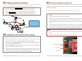
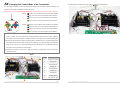
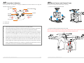
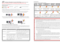
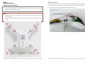
PHANTOM Index INDEX ......................................................................................................................... 2 Advanced Manual A1 SOFTWARE AND DRIVER INSTALLATION .................................................................. 3 V 1.4 2013.03.22 Revision A3 LINKING THE TRANSMITTER AND RECEIVER ............................................................ 4 A2 CONFIGURATION AND FIRMWARE& SOFTWARE UPGRADE ..................................... 3 A4 CHANGING THE CONTROL MODE OF THE TRANSMITTER ......................................... 5 A5 TRANSMITTER CALIBRATION .................................................................................. 7 A6 MOUNT CAMERA AND CAMERA FRAME ................................................................. 8 A7 INTELLIGENT ORIENTATION CONTROL (IOC) FLIGHT (WITH GPS & COMPASS MODULE) ................................................................................................................................... 9 A8 MAINTENANCE ..................................................................................................... 11 ©2013 DJI Innovations. All Rights Reserved. 1 | ©2013 DJI Innovations. All Rights Reserved. 2 | A1 Software and Driver Installation A3 Linking the Transmitter and Receiver Make sure to use the NAZA-M assistant software of 2.0 version (or above 2.0) to carry out firmware upgrade The linking of the transmitter to the receiver of the PHANTOM was carried out before they left the factory. If and parameter configuration. DO NOT use the NAZA-M assistant software bellow 2.0 version. necessary you can link the transmitter to the receiver as follows, for example you replace the transmitter. The 1. Please download the driver DJI Driver Installer and NAZA-M assistant software from the PHANTOM default receiver type is PPM. page of DJI website (http://www.dji-innovations.com/products/phantom/downloads/). 2. Connect the PHANTOM and the PC via the USB cable, power on the PHANTOM system. 3. Run the DJI Driver Installer, and follow the instructions strictly to finish installation. 4. Run the assistant software installer, and follow the instructions strictly to finish installation. DO NOT use the PHANTOM transmitter (receiver) with the third party remote control equipment. 1. Please remove the housing by referring to the section of A8 Maintenance -> Remove the Housing. 2. Locate the receiver module according to the following figure. 3. After powering on the aircraft and the transmitter, if the LED indicator of the receiver on the control board is lit solid red, this means the receiver currently has no connection with any transmitter. 4. Press down the link button for more than two seconds until the LED indicator blinks, then release the button. 5. Push the throttle stick to the lowest position and turn on the transmitter. Then if the LED indicator of the receiver turns off, the link between the transmitter and the receiver has succeeded. (Linking operation can be done only when the LED indicator of the transmitter changes to blinking red .) Note: position. A2 Configuration and Firmware& Software Upgrade 1. If the transmitter can’t enter the linking mode, please check that the throttle stick lies in the lowest You can use your R/C system normally only after the linking is done successfully. Power on your computer. Make sure the computer is connected to the Internet for the first time you use. 2. Switch on the transmitter first, then power on the aircraft. Connect the aircraft to the PC with the USB cable. DO NOT break the connection until configuration or upgrade is finished. 3. Please refer to the “Assembly &Configuration->Step3” section of NAZA-M Quick Start Guide to get the detail of assistant software usage. 4. Receiver Module Refer to the “Appendix-> Firmware & Assistant Software Upgrade” section of NAZA-M Quick Start Guide to get the detail of assistant software usage. 5. If Manual Mode is required, please select “Manual” from the drop down list of Basic->RC->Control Mode Switch in the assistant software. Refer to the “Flying Test-> Step 1 Control Mode Knowledge” Indicator LED Link Button section of NAZA-M Quick Start Guide to get the detail about the Manual Mode. ©2013 DJI Innovations. All Rights Reserved. 3 | ©2013 DJI Innovations. All Rights Reserved. 4 | A4 Changing the Control Mode of the Transmitter The following figure shows the successful change of transmitter mode to Mode 1. Mode1 You can change the operation mode of the transmitter according to the following procedures if necessary.(The operation mode of Mode1 and Mode2 are shown as below.) Make sure to carry out the A5 Transmitter Calibration, if the Control Mode of the Transmitter is changed. Mode1: Throttle, it cannot hold the central position when released. Roll, it can return to the central position when released. Pitch, it can return to the central position when released. Yaw, it can return to the central position when released. Model2: Throttle, it cannot hold the central position when released. Roll, it can return to the central position when released. Pitch, it can return to the central position when released. Yaw, it can return to the central position when released. 1. Remove the right Throttle Ratchet plate and the Ratchet Nut. Assemble the Ratchet Nut to the Nut Hole Location,and fix the Throttle Ratchet onto the Ratchet Nut and the Screw Hole Location. Adjust the screw height of the Throttle Support to change the tension, so as to give you the required operating feel. 2. Remove the left Centering Unit and the Centering Spring. Assemble them to the corresponding position of the Right part (Close to the middle location of the transmitter). Then adjust the height of the Adjusting Screw, so as to give you the required operating feel. (Note: Be careful not to excessively tension the spring when moving and fixing, to avoid damage.) 3. Exchange the connectors of Channel 2(AIN2)and Channel 3 (AIN3). (Note: Take care about the connector direction.) Mode2 1 2 9 3 4 5 8 NO. Name 1 Screw Hole Location 2 Centering Unit 3 Adjusting Screw 4 Ratchet Nut 5 Throttle Ratchet 6 3rd Channel 7 2nd Channel 8 Centering Spring 9 Nut Hole Loc tion 6 ©2013 DJI Innovations. All Rights Reserved. 5 | ©2013 DJI Innovations. All Rights Reserved. 6 | A5 Transmitter Calibration A6 Mount Camera and Camera Frame If the control mode of the transmitter is changed or calibration has not been carried out for a long time, Please mount the Camera and Camera Frame if necessary. transmitter calibration is necessary. (1)Mount the Camera to the Camera Frame IOC Switch S2 OFF CL HL Control Mode Switch S1 GPS ATTI ATTI Joystick Joystick Pitch ( Mode1 ) /T hrottle( Mode2 ) Yaw T hrottle( Mode1 ) / Pitch ( Mode2 ) Roll Power Switch CL:Course Lock HL:Home Lock 1. 2. 3. Set the switch S2 at the OFF position, and the switch S1 at the GPS position Push the Throttle stick to the top position, and push the Pitch stick to the top position. Keep the Pitch (2)Mount the Camera and Camera Frame to the aircraft stick at the top position manually since it can return to the central position when released. Make sure to use the dedicated cross screws of the type M3.0*6, since an over long screw will puncture the Turn on the Power Switch of the transmitter, you should hear the indicator sound of “Di—Di Di” from battery by passing through the battery compartment and could lead to explosion or fire. the transmitter repeatedly. Toggle the switch S2 to the CL position, you should hear an indicator sound of “Di” from the transmitter, in this case, the transmitter has entered the calibration mode. (During this period, the Throttle stick and the Pitch stick must be kept at the top position all the time.) 4. Release the Pitch stick and pull the Throttle stick to the central position. Toggle the switch S1 to the ATTI position; you should hear an indicator sound of “Di” from the transmitter. Then move all of the sticks throughout their complete range several times. After this, put the Throttle stick to the bottom position, and toggle the switch S2 to the HL position, you should hear an indicator sound of “Di” from the transmitter, in this case, the transmitter has been calibrated successfully. ©2013 DJI Innovations. All Rights Reserved. 7 | ©2013 DJI Innovations. All Rights Reserved. 8 | A7 Intelligent Orientation Control (IOC) Flight IOC Flying Test (with GPS & Compass module) Realize an IOC flight by the following procedures. Make sure to open the IOC function in the NAZA-M assistant software before using. Definition of Forward Direction: Quad -rotor will fly along this direction when you push the elevator stick. During the STEP1: same flight Record Graphic Description Nose direction STEP2: ON STEP3: OFF STEP4: ON again Set switch S2 Toggle switch S2 from to OFF position OFF to CL position Set switch S2 Toggle switch S2 from to OFF position OFF to HL position Course Forward direction Home point Lock Over 10m from Home point Before You Start Set switch S1 to GPS or Switch Usually, the forward direction of a flying aircraft is the same as the nose direction. By using IOC, wherever the Record forward ATTI position, S2 to CL Setting direction position nose points, the forward direction has nothing to do with nose direction: In course lock flying, the forward direction is the same as a recorded nose direction. See the following Home Lock figures (The red and blue arrows on the transmitter is corresponding to pitch and roll operations): Set switch S1 to GPS Switch Record position and S2 to HL Setting home point position In home lock flying, the forward direction is the same as the direction from home point to aircraft. See the following figures (The red and blue arrows on the transmitter is corresponding to pitch and roll operations): IOC FLYING NOTES!!! LED will blink quickly if recording is successful. LED will blink between and slowly to indicate the IOC mode only when MC is ready to fly in course lock or home lock modes. Home lock flying requires that 6 or more GPS satellites are found and the aircraft is further than 10m away from the home point. Before you do the home lock flight, you have to fly the aircraft out of the 10m range around home point, and then flip the switch S2 to HL position to fly in home lock when all the requirements are met. If you have already toggled the switch S2 to HL position when the aircraft is still in 10m range Method of Forward Direction & Home Point Recording around home point, and this is the first time you are going to fly in home lock during the current If you use the IOC function, please keep the Forward Direction of Course Lock Flying and the home point of flight, then if all the requirements are met, MC will change into home lock automatically when the Home Lock Flying in mind at any time. There are two ways to record the forward direction and the home point: Course Lock Flight aircraft flies out of the 10m range around home point. Manually and Automatically. You may choose any one record method. When flying in Home Lock mode, if any of the following situations happen, then the system will quit Home Lock flying and automatically enter Course Lock flying. The aircraft will fly in Course Lock Home Lock Flight using the earlier forward direction. Before takeoff, the current position of the 30 seconds after you power on the quad-rotor will be saved as home point when you quad-rotor. push the throttle stick for the first time after 6 or Automatically more GPS satellites have been found. Switch the S2 between OFF and record current nose direction as Manually quickly 3 to 5 times to record the current position of the quad-rotor as the new home point. (CL -> HL -> CL is one time.) 3. The GPS signal becomes bad (The GPS signal LED is blinking Red twice or three times). When the aircraft is flying in home lock mode far away from you and the home point, please do not We suggest that you should know clearly which flight lock method you are going to fly, and you know the locked forward direction or home point, before you switch on IOC mode during the flight. Continuously spinning the aircraft in flight will cause a yaw error. In this case, you can stop or slow down the spinning, so as to have better flight performance. (OFF ->CL-> OFF is one time.) ©2013 DJI Innovations. All Rights Reserved. You toggle the control mode switch to the ATTI. Mode. intentionally knowing. new forward direction after you power on the quad-rotor for 30s. The aircraft fly’s within 10m range of the home point. 2. toggle the IOC switch many times quickly so as to avoid the change of home point without you When 6 or more GPS satellites are found, you can CL position quickly 3 to 5 times to toggle the S2 switch between CL and HL position 1. 9 | ©2013 DJI Innovations. All Rights Reserved. 10 | 2. Extension Power A8 Maintenance There is an extension power cable in the Phantom for DIY use. The voltage from the Extension Power Cable is 1. Remove the Housing the same voltage as the power battery. The red cable is for positive and the grey cable is for negative. Make 1. Remove all the nuts and propellers by using the assistant wrench. 2. Remove the screws marked in the figure below using a Phillips Screwdriver and a Hexagon sure to keep the red cable and the grey cable separated, to avoid short circuit. Screwdriver, and then remove the housing. Note: ExtensionPowerCable Please take good care of the removed parts, for example, screws. Make sure to keep them safe and away from children. DO NOT use any thread locker, since the thread locker may corrode the shell of Phantom, may cause fractures. ©2013 DJI Innovations. All Rights Reserved. 11 | ©2013 DJI Innovations. All Rights Reserved. 12 |