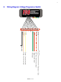
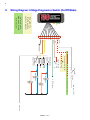
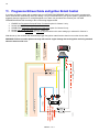
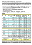
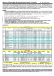
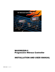
1
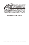
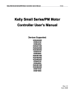
2-Stage Progressive Switch INSTALLATION AND USER MANUAL KWS0020 rev E i Table of Contents Page 1. Overview ........................................................................................................................................................................................... 1 2. Software Installation........................................................................................................................................................................ 1 3. Configuration ................................................................................................................................................................................... 2 3.1 Throttle Position Sensor (TPS) Input......................................................................................................................................... 2 3.2 RPM Input.................................................................................................................................................................................. 3 3.3 Stage Outputs ............................................................................................................................................................................. 3 3.3.1 Progressive Output............................................................................................................................................................. 3 3.3.2 Trigger Input ...................................................................................................................................................................... 3 3.3.3 Ramp Time......................................................................................................................................................................... 4 3.3.4 PWM Frequency ................................................................................................................................................................ 4 3.3.5 RPM On/Off Thresholds .................................................................................................................................................... 4 3.3.6 Relay Output (non-progressive mode only) ...................................................................................................................... 4 3.4 4. Upload / Download Configuration ............................................................................................................................................... 4 Installation ........................................................................................................................................................................................ 5 4.1 Wide-Open-Throttle Setup ......................................................................................................................................................... 5 4.2 RPM Setup Verification ............................................................................................................................................................. 5 5. Software and Firmware Updates .................................................................................................................................................... 6 6. Disclaimer ......................................................................................................................................................................................... 6 7. Warranty .......................................................................................................................................................................................... 6 8. Wiring Diagram: 2-Stage Progressive Switch ............................................................................................................................... 7 9. Wiring Diagram: 2-Stage Progressive Switch (On/Off Mode) ..................................................................................................... 8 10. Wiring Diagram: 2-Stage Progressive Switch (Progressive Mode) ......................................................................................... 9 11. Progressive Nitrous Oxide and Ignition Retard Control ........................................................................................................ 10 KWS0020 rev E 1 1. Overview The 2-STAGE PROGRESSIVE SWITCH is a digital controller that combines the functions of a throttle position sensing switch, two RPM window switches, and two progressive timers all into a very compact module. With the optional FJO high-current driver module, it can drive up to 40 amps per channel. The device also supports low-voltage OEM, V10 or 3 cylinder TACH signals without the need for additional adapters. It also works with TPS signals as low as 2 volts in either rising or falling formats. The manual trigger input allows the driver to over-ride the controller and disable stages manually. 2. Software Installation "ReadMe.txt" this file - provides basic instructions on installing software "2StageSX Installer ?.??.exe" the PC installer file (run this program to install the software on your PC) Run the "2StageSX Installer ?.??.exe" file and follow the instructions. This will install the software and driver files on your PC. Note: For Windows 98SE, the driver files will not be automatically installed. Once you have installed the software and connect the controller, you will be prompted for the location of the driver files by the windows “new hardware wizard”. The files are located on the CD in the “\USB Drivers” subdirectory. If you require additional information, please refer to the Installation/User manual provided with the kit. For your convenience, an electronic copy of this document can be found on this CDROM: "KWS0020 rev ? (2-Stage Progressive Switch Manual).pdf" KWS0020 rev E 2 3. Configuration DO NOT connect the controller to your PC until you have installed the software. The following settings do not require that the controller be connected to the PC until you are ready to UPLOAD. All changes made to the set-up require that you UPLOAD to the controller before installing it in the vehicle. (See Upload/Download section). 3.1 Throttle Position Sensor (TPS) Input Throttle Position Sensor (TPS) allows you to select if the output voltage from the throttle position sensor increases (Rises) or decreases (Falls) at wide-open-throttle (WOT). Note: If used with a WOT switch, set to “Rises” and connect the switch as shown in the wiring diagram. KWS0020 rev E 3 3.2 RPM Input RPM Multiplier selects the correct pulse count for the RPM counter. Use the following as a guide to determine the correct setting: a) Using a TACH signal - TACH signals will typically have 1 pulse per cylinder during 2 revolutions of the crankshaft (1 full cycle) and therefore the correct setting would be ÷(½ the number of cylinders) Example: When using a TACH signal 4 cylinder setting would be ÷2 6 cylinder setting would be ÷3 8 cylinder setting would be ÷4 b) Using a trigger signal from a coil - first determine how often it fires per revolution of the crankshaft. The correct setting would be: x1 for a waste-spark since it fires each revolution of the crankshaft x2 for a full-sequential since it fires every other revolution. This setting must be verified prior to operation. Verifying this setting will require the unit to be installed on the vehicle – see installation instructions later in the manual. 3.3 Stage Outputs The following applies to both Stage 1 and Stage 2. 3.3.1 Progressive Output Progressive Solenoid Driver Connected sets the mode of the output stages. Blank means that the output is configured to drive a relay. With a checkmark in this box, the controller is configured to drive the FJO SOLENOID DRIVER in progressive mode. DO NOT use the progressive mode unless you have the FJO SOLENOID DRIVER module, as you will damage the controller and/or the engine. 3.3.2 Trigger Input Trigger Switch will setting determines if the trigger switch will enable, disable or have no effect on the applicable stage. The trigger switch input can be used to control the output stages manually such as disabling them when the Transmission-brake is engaged, or as a driver over-ride. KWS0020 rev E 4 3.3.3 Ramp Time On Ramp Time (progressive mode only) sets the time period for the controller to ramp from 0% to 100%. DO NOT use the progressive mode unless you have the FJO HIGH CURRENT SOLENOID DRIVER module, as you will damage the controller and/or the engine. 3.3.4 PWM Frequency PWM Frequency is the rate at which the controller cycles the solenoids. This number is determined by the solenoid manufacturer. DO NOT use the progressive mode unless you have the FJO HIGH CURRENT SOLENOID DRIVER module, as you will damage the controller and/or the engine. 3.3.5 RPM On/Off Thresholds Turn On At sets the lower threshold of the RPM window. To change the value, click on the small up and down arrows. To quickly scroll up or down, click and hold the large down arrow while moving the mouse right or left. Turn Off At sets the upper threshold of the RPM window. To change the value, click on the small up and down arrows. To quickly scroll up or down, click and hold the large down arrow while moving the mouse right or left. 3.3.6 Relay Output (non-progressive mode only) Turn On/Off the Relay (non-progressive mode only) allows you to set whether the relay is turned on or off during the RPM window. 3.4 Upload / Download Configuration DO NOT connect the controller to your PC until you have installed the software. To connect the controller to your PC, use the USB cable supplied with the kit. The controller is powered by the USB port on your computer and as such does not require any additional power sources. Plug the USB cable into an available port on your PC. Note: If you are using a USB hub, it must be capable of providing 100mA of current to power the controller. Once the software has identified the FJO 2-STAGE SWITCH, the buttons will become fully visible and the connected ICON will be green. Clicking on the UPLOAD button will store your settings in the controller. The “Config Uploaded” window will appear following a successful upload. You are now ready to install the 2-STAGE PROGRESSIVE SWITCH on the vehicle. KWS0020 rev E 5 4. Installation The 2-STAGE PROGRESSIVE SWITCH is designed to be installed almost anywhere on the vehicle. Select a location that is away from heat sources that can damage the wires. Before permanently installing the device, we recommend that you complete the installation procedure below, as you will need access to the potentiometer and have a clear view of the LEDs for the final steps. Using the wiring diagram applicable to your application, connect the harness as illustrated. Power Input should be connected to the arming switch and fused for 5 amps Ground should be connected to chassis ground as close as possible to the battery and preferably not to the same location that the FJO HIGH CURRENT SOLENOID DRIVER is grounded to. TACH input is designed to work with a 12-volt signal but will work with signals down to 3.5 Volts. Trigger switch input requires a 12-volt signal to activate it. TPS signal input is designed to work with all analog TPS signals or with a 12-volt WOT switch Stage 1 & 2 Control Outputs are designed to trigger the FJO HIGH CURRENT SOLENOID DRIVER or the groundside of a relay coil. FJO HIGH CURRENT SOLENOID DRIVER is designed to handle a maximum load of 40 amps per stage. Exceeding this rating will cause permanent damage 4.1 1) 2) 3) 4) 5) 6) 7) 8) 4.2 1) 2) 3) 4) 5) Wide-Open-Throttle Setup Before connecting the 2-STAGE PROGRESSIVE SWITCH adjust the potentiometer to the initial position by turning it 25 turns clockwise for a rising voltage TPS, or 25 turns counterclockwise for a falling voltage TPS. Disconnect the solenoids from the relays to prevent them from firing. Turn on the ignition power and arm the 2-STAGE PROGRESSIVE SWITCH. Verify that the RED / YELLOW / GREEN LEDs are off with the throttle in the idle position. Push the throttle to the wide-open position (WOT) and hold it. If the GREEN LED is on, adjust the potentiometer to turn it off by turning it clockwise for a rising voltage TPS, or counterclockwise for a falling voltage TPS. Once the GREEN LED goes out proceed to the next step. Now turn the potentiometer the other way until it just comes back on and then one additional turn. Verify that the GREEN LED goes off at IDLE and on at WOT. Repeat steps 4-6 as necessary. RPM Setup Verification Disconnect the solenoids from the relays to prevent them from firing. Turn on the ignition power and start the engine. Arm the 2-STAGE PROGRESSIVE SWITCH. Verify that the RED / YELLOW / GREEN LEDs are off with the throttle in the idle position. Slowly increase the throttle until you reach the Turn On At RPM setting that you downloaded for stage 1. KWS0020 rev E 6 6) Watch the YELLOW LED. If you set the correct RPM multiplier it will come on just as you reach the target RPM. 7) Now repeat steps 5 and 6 and watch the RED LED and use the Turn On At RPM setting that you downloaded for stage 2. 8) If the LEDs come on at the right RPM, then you selected the correct multiplier. 9) If the LEDs come on too late then the RPM multiplier is too high and you need to set the multiplier to ½ the previous setting and repeat the RPM set-up verification. 10) If the LEDs come on too soon then the RPM multiplier is too low and you need to set the multiplier to 2x the previous setting and repeat the RPM set-up verification. Note: DO NOT use the half-step multipliers unless this is a 3 or 10 cylinder application. The installation is complete! 5. Software and Firmware Updates Please take a moment to register your product online at "http://www.fjoracing.com". Registered owners are entitled to download the free updates for the 2-Stage Progressive Switch and related software. 6. Disclaimer FJO Racing Electronics shall not be held responsible for any damages, howsoever caused, to any persons or equipment during the installation or operation of its products. FJO Racing Electronics products are meant for off-road use only, and make no claims as to the unit’s ability to meet local safety or emissions laws. 7. Warranty FJO Enterprises Inc. (FJO) warrants the material and workmanship of the equipment, components and parts manufactured by FJO against defects under normal use and service. This warranty shall extend for 180 days from the date of manufacture provided that the customer first returns the defective part or component through an authorized distributor, shipping costs prepaid. Prior to returning a product for warranty inspection, the customer must contact FJO’s service department with the product serial number to receive a WARRANTY CLAIM NUMBER. Units returned without this number will be refused. FJO may at its option, repair or replace without cost for parts and labour, the defective product. This warranty does not cover finishes, normal wear and tear, nor does it cover damage resulting from accident, misuse, dirt, tampering, unreasonable use, service attempted or performed by unauthorized service agencies, failure to provide reasonable maintenance, or FJO products that have been modified or used for commercial reasons. FJO specifically does not warrant equipment, parts or components purchased by FJO or the customer from any third party manufacturers or suppliers. Rather, for any defect in respect of equipment, parts and components purchased from third party manufacturers and suppliers, the customer shall have recourse only to the terms of the warranty of that particular manufacturer or supplier. Any recommendations made by the third party manufacturer or suppliers concerning the use or application of their products are those of the manufacturer or supplier, and FJO extends no warranty with respect to the results obtained for their use. FJO does not warranty those products in any way beyond the term of the warranty extended by the manufacturer or supplier. The warranty provided above, FJO’s obligations and liabilities hereafter, and the rights and remedies of the customer are exclusive and in substitution for, and the customer waives all other warranties, guarantees, obligations, liabilities, rights and remedies, expressed or implied, arising by law or otherwise, including (without limitation) the implied warranties of merchantability or fitness of purpose, and any obligations or liability of FJO arising from tort, or loss of use, revenue or profit, or for incidental or consequential damage. KWS0020 rev E 7 Wiring Diagram: 2-Stage Progressive Switch 8. A B C D E F G H J K W hite Whit e/Red Red Green Yellow Orange Black Stage 1 control output Stage 2 control output RPM input Trigger switch input Power (+12V) Throttle position sensor input 5A Fuse Ground KWS0020 rev E Required if no throttle position sensor is present Not used when Wide-open throttle switch is used A B C D E F G J H K W hite Whi te/Red Red Green Yellow Ora nge Black Ground Arming SW 5A Fuse Power (+12V) to Throttle -posi tion S ensor to TACH signal Fuel Nitrous Oxide Nitro us Oxide Wide-open Throttle SW Trigger Switch Stage 1 Relay Stage 2 Relay Fue l to batte ry KWS0020 rev E Wiring Diagram: 2-Stage Progressive Switch (On/Off Mode) 9. 8 Required if no throttle position sensor is present W hite White/Red Red Gre en Yell ow B lack Ground Arming SW Wide-op en Throttle SW Trig ger Switch 5A Fuse Power ( +12V) to Throttle-pos ition Sens or Fuel S olenoid to TACH si gnal Fuel S olenoid Stage 2 to battery Nitrous Solenoid Stage 1 Nitrous Solenoid KWS0020 rev E Orange Not used when Wide-open throttle switch is used 9 10. Wiring Diagram: 2-Stage Progressive Switch (Progressive Mode) 10 11. Progressive Nitrous Oxide and Ignition Retard Control If you have an ignition system with a retard trigger, the 2-STAGE PROGRESSIVE SWITCH can provide a progressive nitrous channel and automatically retard your timing. First you must determine if your ignition system’s retard function is triggered when the input has a 12 volt signal applied to it or when it is grounded. Now connect your 2-STAGE PROGRESSIVE SWITCH according to the correct wiring diagram below. 1. 2. 3. 4. 5. ENABLE the Progressive Solenoid Driver Connected option for Channel 1 only. Set the desired parameters in Channel 1’s menu. DISABLE the Progressive Solenoid Driver Connected option for Channel 2 only. Set the Turn On /Off the Relay option to TURN ON. Set the Channel 2 Turn On At and Turn Off At parameters to the same settings you selected for Channel 1. With this set-up, the controller will automatically trigger the ignition retard function when it turns on the nitrous oxide. WARNING: Failure to set the options correctly will result in engine damage due to the ignition not being retarded when the nitrous oxide is on. W hite White/R ed Red Green Ye ll ow Black Orange Ignition retard when “12 volts” applied to trigger Ignition retard when “ground” applied to trigger Trigg er Switch Gro und Armi ng SW 5 A Fu se Power (+1 2V) to T hrottle-po sition Sen sor to TAC H sig nal Fue l Sol enoid N itro us Solenoid Stage 1 to bat tery To ignition reta rd trigger To ignition retard trigger KWS0020 rev E