1
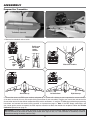
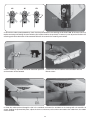
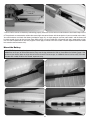
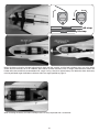
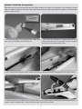
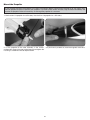
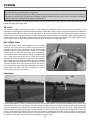
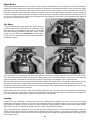
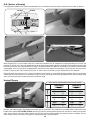
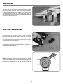
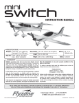
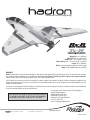
™
Vectored Thrust Flying Wing
Wingspan: 33.5 in [850mm]
Wing Area: 408 sq in [26.3 dm2]
Weight: 29.6 – 31.3 oz [840 – 885 g]
Wing Loading: 10.4 – 11.0 oz/sq ft [32 – 34 g/dm2]
Length: 33.5 in [850mm]
Radio: 6-channel computer radio with elevon mixing
Motor: 35-36-2200kV Outrunner, 40A ESC
WARRANTY
Flyzone® guarantees this kit to be free from defects in both material and workmanship at the date of purchase. This warranty does not cover
any component parts damaged by use or modification. In no case shall Flyzone’s liability exceed the original cost of the purchased kit.
Further, Flyzone reserves the right to change or modify this warranty without notice.
In that Flyzone has no control over the final assembly or material used for final assembly, no liability shall be assumed nor accepted for any
damage resulting from the use by the user of the final user-assembled product. By the act of using the user-assembled product, the user
accepts all resulting liability.
If the buyer is not prepared to accept the liability associated with the use of this product, the buyer is advised to return this kit immediately
in new and unused condition to the place of purchase.
For warranty claims Contact Flyzone Product Support:
Flyzone Product Support:
3002 N Apollo Drive Suite 1
READ THROUGH THIS MANUAL BEFORE STARTING ASSEMBLY.
Champaign, IL 61822 USA
IT CONTAINS IMPORTANT INSTRUCTIONS AND WARNINGS
Telephone: (217) 398-8970 ext. 6
CONCERNING THE ASSEMBLY AND USE OF THIS MODEL.
Fax: (217) 398-7721
E-mail: [email protected]
™
Flyzone, a Hobbico company.
© 2013 Hobbico, Inc. All rights reserved.
flyzoneplanes.com
FLZA3612/14Mnl
INTRODUCTION
The Hadron has something for everybody—in addition to the crazy “party tricks” including flat spins that are ridiculously fast and
astonishingly flat, the Hadron can also be flown pedal-to-the-metal like a pylon racer, or slow-and-easy like a park flyer. If you
want to get your Hadron airborne quickly, might as well get your batteries charging because programming your radio should take
only a few minutes and assembly takes even less time!
For the latest technical updates or manual corrections scan the QR code, or visit the Flyzone web site at
www.flyzoneplanes.com. Click the airplane icon at the top of the page, then select the Hadron when the
airplane page opens. A “Tech Notice” box indicates corrected or updated technical information.
ITEMS REQUIRED
Radio System
The Hadron may be flown with a 4-channel radio that has elevon mixing, but a computer radio (such as the Tactic TTX650) with
basic features including dual rates, exponentials, a programmable switch and a flight timer will allow you to enjoy your Hadron
to its fullest.
The Tx-R Edition of the Hadron requires:
Tactic TTX650 transmitter (TACJ2650)
OR
Minimum 4-channel transmitter capable of elevon mixing AND AnyLink SLT Universal Radio Adapter (TACJ2000)*
*Visit tx-ready.com to see AnyLink compatibility chart or contact Flyzone Product Support at the contact information on the front cover of this manual.
The Rx-R Edition of the Hadron requires:
Minimum 4-channel transmitter capable of elevon mixing and receiver.
Note: For either edition of the Hadron, if flying with a 4-channel radio, the vectoring servo and rudder servo will have to be
connected to the rudder channel via Y-connector (TACM2530 universal).
Battery
The Tx-R edition of the Hadron includes the recommended 3S battery, but the Hadron can also be flown on 4S and you’ll want
extra batteries for more flying (more about 3S and 4S batteries on page 9). Following are the recommended batteries:
3S 11.1V 2200mAh 30C LiPo (GPMP0861)
4S 14.8V 2200mAh 30C LiPo (GPMP0862)
Charger
The Smart Charger included with the Tx-R is a safe way to charge your LiPo battery, but it’s basic and just enough to get you
started. A suitable upgrade over the Smart Charger (or a recommended charger for the Rx-R version) is the Duratrax Onyx
235 AC/DC Advance Peak Charger (DTXP4235). The 235 features 110V AC or 12V DC input power, adjustable charge rate
(to charge the recommended 2200mAh batteries in as little as 30 minutes) and an LCD digital display screen (so you can see
how much capacity it took to charge the battery - handy for calculating optimum flight time).
Spare Propellers
Prop breakage on the Hadron is a rare occurrence, but if you ever do break or damage a prop keep a few spares on-hand so
you’ll never have to be grounded:
6 x 5 prop (3S) FLZA6528
5 x 5 prop (4S) FLZA6527
2
ASSEMBLY
Program Your Transmitter
1. Remove the turtledeck and set aside.
Rudder servo
arm rotates
counterclockwise
Motor
rotates
right
Motor turns clockwise
Left elevon down
Both elevons up
Right elevon up
2. Connect the servos and ESC to your receiver and power up the system with a battery so you can operate the servos and motor
(if not done so already, this may also require linking the receiver to your transmitter). Program your transmitter and connect the
servos to the receiver so the controls respond correctly to stick movements—if using the TTX650 simply follow the programming
instructions and connect the servos into the receiver as instructed on page 11. Note: If the ESC beeps continuously and
you cannot get the servos to respond, the ESC requires calibration to detect the throttle stick endpoints. Follow the Throttle
Calibration procedure on page 13.
IMPORTANT!: If using a Tactic radio, be certain to link the receiver to the transmitter after the throttle channel has been
reversed. Otherwise, the motor will switch to full-throttle when signal is lost (i.e., if the transmitter is accidentally turned off
before disconnecting the battery from the ESC).
3
NO
NO
YES
90°
3. Still with the radio system powered up, check that the pushrod hole in the vectoring servo wheel is 90° to the servo (this may
require removing and rotating the servo wheel to find another hole for the pushrod). If necessary, also adjust the V-bend in the
vectoring pushrod so the motor will be centered. Reinstall the screw for the vectoring servo wheel.
4. Also if necessary, adjust the clevises on the elevon pushrods
so the elevons will be centered.
5. Mount the vertical stabilizer to the turtledeck with two
M3 x 6 screws.
6. Guide the rudder pushrod through the slot in the turtledeck and mount the turtledeck to the fuselage with six more M3 x 6
screws. Holding the pushrod with pliers, adjust the clevis as necessary so that when connected to the rudder horn, the rudder
will be centered.
4
7. When all of the controls are hooked up and working properly, mount the receiver with the included adhesive-back hook & loop material.
8. The pushrods are connected to achieve the correct high-rate control throws with the end points in your transmitter set to 100%.
You could measure and check the throws (provided on page 12), or simply program your low-rates to 60% and the throws will
be close enough for you to fine tune from there. While you’re at it, your Hadron will also benefit from -30% exponential on highrate and -20% exponential on low-rate (negative values apply to Futaba and Tactic radios—control response should be softer/
less-sensitive around center stick).
Mount the Battery
IMPORTANT: If performing flat spins or other rigorous maneuvers, the 4S battery must be captured by two straps. It is also
critical that the straps (for 3S or 4S batteries) wrap over the top and down the side as illustrated on the following page. If the
location of your battery does not align with two of the “channels” for two straps, an additional channel can be easily cut under
the tube with a hobby knife for that second, important strap.
5
7-3/4" [195mm]
7" [180mm]
4S strap
3S strap
Mount the battery using the included adhesive-back hook-and-loop material and the hook-and-loop straps cut to the length
shown. With the ElectriFly 3S or 4S 2200mAh 30C batteries (or other batteries similar in weight) mounted where shown, the
Hadron will balance within the recommended C.G. range. If using a heavier or lighter battery, first determine where the battery
must be positioned to get the Hadron to balance within the range specified on page 12.
When removing the battery, the hook and loop material is easily separated with a screwdriver.
6
Optional: Install the Canopy Hook
Bold pilots who have the courage to flat-spin the Hadron suddenly and violently are advised to install the optional canopy
hook for additional canopy security. Pilots who fly the Hadron “normally” (performing traditional aerobatics and speed flying)
need not install the hook.
1. Cut the sharp edges off the opening of the rubber band
hook, then glue the hook to the base with CA.
2. Use medium-grit sandpaper to roughen the inside of the
canopy where the hook is to be glued. Use CA to securely
glue the base into position where shown.
3. Use a small hex key wrench or similar to loop the included rubber band under the fuselage tube, then pull the ends up.
4. Connect the ends of the rubber band to the hook. When removing the canopy to exchange batteries between flights, no
need to unhook the rubber band—simply lift off the canopy and swing it to the side.
7
Mount the Propeller
It’s not essential to balance the propeller, but to extract the highest degree of performance possible out of your motor, use a
precision propeller balancer to balance your propeller. If you feel or hear excess vibration, stop the motor immediately and
examine the propeller. Balance if necessary, or exchange the propeller for a new one.
1. Use the 6.0 x 5.0 propeller for a 3S battery. Use the 5.0 x 5.0 propeller for a 4S battery.
2. Fit the propeller to the collet assembly in the “tractor”
configuration (front of the prop facing forward) and tighten the
nut using a screwdriver shaft to torque it down.
3. If you haven’t yet done so, install the magnetic nose cone.
8
FLYING
Before flying your Hadron be certain to follow all of the instructions accompanying your radio control system for charging the
transmitter batteries and performing a range check.
Also be certain to periodically inspect the hook-and-loop straps retaining the battery to make sure they hold securely. Replace
the straps with new material as necessary. Frequently inspect the motor wires for signs of wear or chafing. If necessary,
protect the wires with additional shrink tubing or suitable tape.
The Hadron is an easy flyer—you could take it out right now and get the hang of it pretty quickly, but even experienced pilots will
benefit from these basic flight notes:
3S vs 4S
The Hadron is perfectly content flying on either a 3S or 4S battery—provided of course you use the correct propeller. On 4S
with the 5.0 x 5.0 propeller the motor draws about 40A static (about 30A average in-flight). On 3S with the 6.0 x 5.0 propeller the
motor draws about 33A static (about 21A average in-flight). If you like to fly pedal to the metal you’ll find the Hadron is faster on
4S, but still flies slowly well and performs flat spins spectacularly. If you prefer to get used to your Hadron before going all-out,
consider starting out on 3S where the Hadron will be slower (but definitely not slow at full-throttle!) and slightly lighter for even
easier launches and landings. The reduced current draw on 3S also results in longer flight times.
Set a Flight Timer
If flying your Hadron on 3S, set your flight timer to 3-1/2 minutes.
If flying on 4S set your timer to 3 minutes. Those are about the
minimum flight times flying full-throttle with the recommended
2200mAh batteries. Check your battery voltage and recharge
capacity when you land and adjust your timer accordingly—
treating your batteries conservatively, resting, unloaded voltage
after a flight should be no less than 3.7V/cell and recharge
capacity (the amount of capacity that goes back into your battery
indicating how much you used) should be no more than 1760mAh
(80% of 2200mAh). Flying “normally,” your flight time may end up
closer to 6 minutes on 3S and 5 minutes on 4S (or even longer),
but it all depends on your flying style and throttle usage, so start
conservatively and adjust your timer as required so as not to
over-capacity discharge your batteries.
Launching
Launching the Hadron is a cinch. It’s so easy that you can do it yourself; however, if it makes you feel better, you can always have
someone else launch it on its first flight. It’s best to launch the Hadron on low rates and at full throttle. Simply hold it by the finger
grips on the bottom of the fuselage, advance the throttle to full and throw it upward into the wind at a 10-15° angle. Be extremely
careful to keep your throwing hand away from the propeller. The best way to do that is good follow- through after the throw; let
your arm arc downward immediately after you release the Hadron. If you decide to do the first launch by yourself, we recommend
that you dial in five to seven clicks of up trim just to make sure it climbs. However, that’s only for the first flight; once the Hadron
is trimmed for level flight, it will climb out rapidly regardless of launch angle.
9
Flight Basics
Until you get some experience with your Hadron and really develop a feel for how it reacts to rudder input, realize that the Hadron
exhibits considerable negative pitch coupling and positive roll coupling to large amounts of rudder—when you give right rudder
the Hadron rolls right and pitches down (and vice-versa). Because of this, you’ll pretty much fly the Hadron like a 3-channel
leaving the rudder stick alone until you’re ready to do a flat spin (at least until you get used to this tendency and learn how to use
it to your advantage for other spectacular maneuvers). With vectoring-only, coupling is greatly reduced—the Hadron will still flat
spin, but not as quickly. You can also turn the vectoring off and, with experience and practice, hold a respectable knife edge with
the correct mix of elevator and aileron.
Flat Spins
There are several ways to enter the flat spin, but the easiest is
to pull to a vertical up line. Once the line is established, simply
slam the sticks to the opposite, upper corners (full throttle/
left rudder/vectoring and down elevator/right aileron) and the
Hadron will enter the flat spin immediately. (For this kind of
flat spin entry it is advisable to install the rubber band hook as
illustrated on page 7.)
Once the Hadron starts spinning you can release the right stick, but continue to hold the left stick until you want the spin to stop.
The easiest way to exit the flat spin is to center the rudder/vectoring stick, but leave the throttle at full. Usually, the Hadron will
stop spinning within a revolution or two and fly out. To exit the spin quickly, apply opposite (right) rudder/vectoring.
When exiting the flat spin, always be ready to roll the Hadron upright (or be prepared to fly upside-down) because occasionally
the Hadron will exit the spin inverted. With practice you’ll be able to get the Hadron to spin and exit the spin on command.
With practice you can do variations of the flat spin including slowing it down, slowing it down then speeding it back up, or even
transitioning from one direction to the other.
With more practice you can even fly along at low throttle, perform one quick spin, exit and continue along on the original flight
path (this maneuver is usually more successful when performed inverted). The permutations and combinations of maneuvers
that can be done with combinations of rudder and vectoring are virtually endless.
Landing
Same as the launch, the Hadron is exceptionally easy to land. Landings will be smoothest if you switch back to low rates. Simply
throttle down and make your approach. It may take a couple of attempts to learn the Hadron’s glide path, but it’s always easy to throttle
up to lengthen the approach (if you’re coming in too short) or abort the landing to perform a routine fly-by to make another attempt.
After you land, as soon as conveniently possible, open the canopy and disconnect the battery.
The chances of breaking a propeller are virtually none for normal landings on grass—we’ve performed countless landings on
smooth and rough grass (and a few on paved runways) without ever breaking a prop. But if you have a crash landing—especially
on hard or uneven ground—the chances of breaking a prop will be higher, so keep a few spare propellers on-hand so you’ll never
have to be grounded.
10
SUPPLEMENTARY SETUP INSTRUCTIONS
Tactic TTX650 Programming
These instructions mix the vectoring and rudder servos and allow either to be turned off in-flight via switch E.
I. Servo Connections to Receiver
Ch. 1: Right Elevon Servo
Ch. 2: Left Elevon Servo
Ch. 3: Throttle
Ch. 4: Vacant-not used
Ch. 5: Vectoring Servo
Ch. 6: Rudder Servo
II. Radio Programming
A. MODEL SETUP (Press and hold “ENTER”)
WING TYPE
FLAP: 2AI (2 Aileron)
TAIL: Delta
B. SETTINGS (Press “ENTER”)
1. SERVO SET (Reverse)
Channel 1: REV
Channel 2: REV
Channel 3: REV
Channel 4: NOR
Channel 5: NOR
Channel 6: NOR
2. -TRAVEL+ (End Points)
Channel 5 (Vector Servo): 125%
All others default: 100%
3. DUAL, EXPO
Personal preference: Set low rates to 60%, –30% exponential
on aileron, elevator, rudder.
4. PROGRAMMABLE MIXER (Vector Mixing)
Note: Sub-trims must be used to trim rudder and vectoring servos.
Mix 1
CH4 > CH5
Mix 2
CH4 > CH6
RATE L
+100%
+100%
RATE R
+100%
+100%
OFFSET
0%
0%
SE (Switch E)
SE (Switch E)
Switch Position 0 [L] (Rudder + Vectoring)
ON (1)
ON (1)
Switch Position 1 [M] (Rudder Only)
OFF (0)
ON (1)
Switch Position 2 [H] Vectoring Only
ON (1)
OFF (0)
CTRL
5. TIMER
3S (2200mAh, 6 x 5 prop): 3-1/2 minutes (adjust accordingly)
4S (2200mAh, 5 x 5 prop): 3 minutes (adjust accordingly)
11
C.G. (Center of Gravity)
If using batteries different than those recommended in this instruction manual be certain to balance your Hadron as follows:
4th Mark
6th Mark
While checking the C.G. the Hadron must be in ready-to-fly condition with all components installed including the receiver and
propeller. There are nine C.G marks molded into the top of the fuselage on both sides of the turtledeck. Counting backward from the
first mark at the front, the recommended C.G. range is anywhere between the 4th mark and the 6th mark, with the recommended
starting point at the 5th mark (which is approximately even with the front edge of the turtledeck). The easiest way to balance your
Hadron is simply to stick T-pins into the wing at the 4th and 6th marks and make sure your Hadron balances in-between.
Balanced nearer the front of the C.G. range you’ll notice that the Hadron is more stable and flies smoother, but can fly and land
slower when balanced nearer the aft end of the range. If most of your flying consists of high-speed passes and full-throttle flying
you’ll want to balance your Hadron nearer the front of the range.
Control Throws
These are the recommended control surface throws:
RUDDER ELEVATOR AILERON
HIGH RATE
LOW RATE
Up
3/4" [19 mm]
19°
Down
3/4" [19 mm]
19°
Up
1/2" [13mm]
13°
Down
1/2" [13mm]
13°
Up
3/4" [19 mm]
19°
Down
3/4" [19 mm]
19°
Up
1/2" [13mm]
13°
Down
1/2" [13mm]
13°
Right
3/4" [19 mm]
15°
Left
3/4" [19 mm]
15°
Right
Left
1-1/4" [32mm] 1-1/4" [32mm]
25°
25°
Elevator and aileron throw is measured at the widest part of the elevons at the root end and rudder throw is measured at the
bottom of the rudder. VECTORING THROW: Vectoring is primarily used to perform spectacular flat spins. In most instances then
you’ll want maximum vectoring throw. However, you may discover maneuvers where less vectoring throw is required. You can
either simply use less stick input, or program a vectoring low rate to your preference.
12
ESC PROGRAMMING INSTRUCTIONS
I. Throttle Calibration:
1. Remove the propeller.
2. If using a computer radio, set end points for throttle channel to 100% and trims and sub trim to 0.
3. Turn on the transmitter. Advance throttle stick.
4. Connect battery to ESC. Hear three tones… “ 1 2 3” followed by two short beeps…”beep beep.”
5. Lower throttle stick all the way. Hear short beeps (3 beeps for 3S or 4 beeps for 4S), followed by one longer beep.
6. Throttle is calibrated. Disconnect battery.
II. Programming Instructions:
The ESC is factory-set for the Hadron—other than possibly having to calibrate the throttle, there is nothing that needs to be done
with the ESC. However, should you desire to re-program the ESC to suit different requirements, following are full programming
instructions:
ESC SPECIFICATIONS
Constant Current
Burst current (<10 seconds)
BEC mode
BEC output
Battery cell count
Weight
Dimensions
FACTORY DEFAULT SETTINGS
40A
55A
Switching
5V, 3A (5 servos)
2S – 4S LiPo, 5 – 12 cell NiMH
43g
6mm x 25mm x12mm
Motor brake
Battery type
LVC mode (low-voltage cutoff)
Auto-detect* low-voltage cutoff
Start mode
Timing
OFF
LiPo
Soft cut-off
3.15 V/cell
Normal (0.3 seconds)
Low (3.75°)
*Automatically detects 4-cell or 3-cell LiPo.
The brake strength, battery type, cutoff mode, cutoff voltage, start mode and timing are all programmable. Follow the programming
instructions to change any of these settings from the factory-set defaults.
1. ACCESS PROGRAMMING MENU:
A. Turn on the transmitter. Advance throttle stick all the way.
B. Connect the battery to the ESC.
Hear three tones (“ 1 2 3”) followed by:
Two short beeps (“beep beep”) followed by:
5-second pause followed by:
Five tones (“ 1 2 3 4 5”)
PROGRAMMING MENU FUNCTION
The ESC is now in the Programming Menu
and will loop through a sequence of beeps, each
representing a function in the menu that can be
reprogrammed. (You don’t have to do anything
at this time; you can simply listen to the beeps
identifying which function correlates to which
sequence of beeps.)
1
2
3
4
5
6
7
8
One short beep
Two short beeps
Three short beeps
Four short beeps
One long beep
One long beep, one short beep
One long beep, two short beeps
Two long beeps
“beep”
“beep beep”
“beep beep beep”
“beep beep beep beep”
“beeeep”
“beeeep beep”
“beeeep beep beep”
“beeeep beeeep”
* Determines how the motor stops
when low-voltage is detected:
Soft = motor will quit gradually,
Hard = motor cull cut immediately.
13
Brake
Battery type
Cutoff mode*
Cutoff Voltage
Start mode**
Timing
Set the ESC to default
Exit programming
** Determines how the motor starts.
Normal is recommended for
airplane (fixed-wing). Soft or
super-soft is for helicopters.
2. After the sequence of beeps representing the desired function, lower the throttle stick to enter the programming mode for that
function. The ESC will beep as indicated below waiting for your command to change the setting:
Advance the throttle after number of beeps (one
beep, two beeps, three beeps) indicating the new
setting. Hear the tones (“ 1 2 1 2”) indicating the
value has been set and saved. Immediately lower the
throttle stick (within two seconds) to exit programming
mode proceeded by the number of short beeps
counting the number of LiPo cells, followed by one
long beep (“beeep”) indicating the model is ready to
fly. Or, disconnect battery at any time to exit
programming mode.
1
2
3
4
5
6
Function
One Beep
Two Beeps
Three Beeps
Brake
Battery type
Cutoff mode
Cutoff voltage
Start mode
Timing
Off
LiPo
Soft
Low (2.85 V)
Normal
Low (3.75°)
On
NiMH
Hard
Medium (3.15 V)
Soft
Medium (15°)
Brake
Battery type
Cutoff mode
High (3.3 V)
Super soft
High (26.25°)
If the throttle stick is left in advanced programming mode, programming will resume where it left off—simply listen for the
sequence of beeps that represents the next function, then lower throttle stick to enter the programming mode for that function.
EXAMPLE:
To set brake from the factory default of “off” to “on”:
1. Advance the throttle stick. Turn on the transmitter.
2. Connect battery.
Three tones (“ 1 2 3”) followed by:
Two short beeps (“beep beep”) followed by:
5-second pause followed by:
Five tones (“ 1 2 3 4 5”)
The ESC is now in the Programming Menu.
3. After one short beep (“beep”) lower throttle stick. You are now in the brake programming function.
4. Listen for beeps: one beep = brake off, two beeps = brake on. If you do nothing ESC will simply
loop through the sequence of beeps—once, then twice, then once, then twice, etc. waiting for your
command to turn the brake on or off. To turn the brake on advance throttle stick after the two beeps.
Listen for the tones (“ 1 2 1 2”) indicating that the setting has been set and saved. If that’s all you
wanted to set, immediately lower the throttle stick (within two seconds) to exit programming mode,
then hear the number of beeps correlating to the number of cells in your battery (three or four)
followed by one long beep (“beeep”) indicating that the model is ready to fly.
III. ESC Troubleshooting Guide:
Problem
Reason
Action
Motor does not work, no tones or beeps are
coming from the ESC.
Motor does not work, Alert Tone sounds
(“beep beep,” “beep beep,” “beep beep,”…)
There is a problem with the connection between
the battery and ESC.
Battery voltage is too high or too low.
Check the plugs or change the plugs if the wires
are damaged.
Make sure the battery is charged and/or you are
using the correct battery.
Motor does not work, Alert Tone sounds
(Long beeps: “beeep beeep beeep…”)
There is a problem with the throttle signal.
Check the transmitter and receiver and check the
connection between the ESC and the receiver.
Motor does not work, Alert Tone sounds
(Rapid beeps: “beepbeepbeepbeepbeep…”)
Throttle stick is not in the lowest position, or
throttle needs to be calibrated.
Lower the throttle stick all the way, or recalibrate
the throttle per calibration instructions.
Motor does not work, five tones are sounded
(“ 1 2 3 4 5”) after the two beeps.
The direction of the throttle channel is reversed
and the ESC has entered the Programming Menu.
Set the throttle direction in the transmitter the
other way.
The motor turns the wrong direction.
The three motor wires are incorrectly connected
to the ESC.
Swap any two of the motor/ESC wire connections
with each other.
14
REPAIRS
AeroCell foam is easily reparable. Pliable glue such as canopy
glue is the very best, but requires tape to hold the parts together
while the glue dries overnight. CA is usually the go-to adhesive
for repairing AeroCell and with a little CA accelerator the repair
will be complete in minutes. For a seamless repair excess CA
may be removed from the surfaces with CA debonder (debonder
will affect the decals and paint).
MOTOR REMOVAL
If you ever have to remove the motor, the top and bottom
moveable motor mount halves must be separated. This is done
by taking out the top and bottom 4mm pivoting screws, the
four 3mm motor mount screws and finally the four self-tapping
screws holding the halves together.
Once the motor comes out with the top moveable mount,
disconnect the motor from the ESC and guide the wires out
through the molded-in retainer.
NOTE: If considering a different motor other than the 35-36-2200
(FLZA6522) included with this kit, make sure the orientation of the
mounting holes will allow the wires to align with the retainer in the
moveable mount. Otherwise, the motor will not fit.
Motor wires
16mm
19mm
15
PROTECT YOUR MODEL, YOURSELF & OTHERS...
FOLLOW THESE IMPORTANT SAFETY PRECAUTIONS
1. Your Hadron should not be considered a toy, but rather a sophisticated, working model that functions very much like a full-size
airplane. Because of its performance capabilities, the Hadron, if not assembled and operated correctly, could possibly cause
injury to yourself or spectators and damage to property.
2. You must assemble the Hadron according to the instructions. Do not alter or modify the model, as doing so may result in
an unsafe or unflyable model. In a few cases the instructions may differ slightly from the photos. In those instances the written
instructions should be considered as correct.
3. You must use an R/C radio system that is in good condition. All components must be correctly installed so that the model
operates correctly on the ground and in the air. You must check the operation of the model and all components before every
flight.
4. If you are not an experienced pilot or have not flown this type of model before, we recommend that you get the assistance of
an experienced pilot in your R/C club for your first flights. If you’re not a member of a club, your local hobby shop has information
about clubs in your area whose membership includes experienced pilots.
5. While this kit has been flight tested to exceed normal use, if the plane will be used for extremely high stress flying, such as
racing, or if a motor or battery larger than ones in the recommended range is used, the modeler is responsible for taking steps
to reinforce the high stress points and/or substituting hardware more suitable for the increased stress.
We, as the kit manufacturer, provide you with a top quality, thoroughly tested kit and instructions, but ultimately the quality and
flyability of your finished model depends on how you build it; therefore, we cannot in any way guarantee the performance of your
completed model, and no representations are expressed or implied as to the performance or safety of your completed model.
Motor Safety Precautions
Failure to follow these safety precautions may result in severe injury to yourself and others.
• Wear safety glasses whenever running motors.
• Keep your face and body as well as all spectators away from the plane of rotation of the turning propeller.
• Keep loose clothing and objects such as pencils or screwdrivers that may fall out of shirt or jacket pockets away from the prop.
ACADEMY OF MODEL AERONAUTICS
If you are not already a member of the AMA, please join! The AMA is the governing body of model aviation and membership
provides liability insurance coverage, protects modelers’ rights and interests and is required to fly at most R/C sites.
Academy of Model Aeronautics
5151 East Memorial Drive
Muncie, IN 47302-9252
Tele. (800) 435-9262
Fax (765) 741-0057
modelaircraft.org
REPLACEMENT PARTS
Replacement parts may be purchased from your local hobby dealer or on-line. For assistance with defective or missing parts
or purchasing replacement parts, contact Flyzone Product Support at the contact information on the front cover of this manual.
FLZA6515
FLZA6516
FLZA6517
FLZA6518
FLZA6519
FLZA6520
Wing & Fuselage Body
Turtledeck
Vertical Stabilizer
Canopy
Canopy Hook
Nose Cone
FLZA6521
FLZA6522
FLZA6523
FLZA6524
FLZA6525
FLZA6526
Vectoring Motor Mount
Brushless 35-36-2200kV Motor
40A ESC
Metal Gear Vector Servo
Servo
Spinner Assembly
16
FLZA6527
FLZA6528
FLZA6529
FLZA6530
FLZA6531
5x5 Propeller (2)
6x5 Propeller (2)
Pushrod Set
Plastic Skids
Screw Set