1
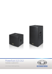
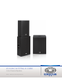
A 112A | A 115A | A 118A
A-Line Powered Speakers
Owner`s Manual | Bedienungsanleitung
A 112A | A 115A | A 118A
2
A 112A | A 115A | A 118A
CONTENTS
INTRODUCTION . . . . . . . . . . . . . . . . . . . . . . . . . . . . . . . . . . . . . . . . . . . . . . . . . . . . . . . . . . . . . . . . . . . . . . . . . . . . . . .
Scope of Delivery, Unpacking and Inspection . . . . . . . . . . . . . . . . . . . . . . . . . . . . . . . . . . . . . . . . . . . . . . . . . .
Warranty . . . . . . . . . . . . . . . . . . . . . . . . . . . . . . . . . . . . . . . . . . . . . . . . . . . . . . . . . . . . . . . . . . . . . . . . . . . . . . .
HF-Interference . . . . . . . . . . . . . . . . . . . . . . . . . . . . . . . . . . . . . . . . . . . . . . . . . . . . . . . . . . . . . . . . . . . . . . . . . .
INSTALLATION . . . . . . . . . . . . . . . . . . . . . . . . . . . . . . . . . . . . . . . . . . . . . . . . . . . . . . . . . . . . . . . . . . . . . . . . . . . . . . . .
Controls, Indicators and Connections . . . . . . . . . . . . . . . . . . . . . . . . . . . . . . . . . . . . . . . . . . . . . . . . . . . . . . . .
Power Amplifier and Cooling . . . . . . . . . . . . . . . . . . . . . . . . . . . . . . . . . . . . . . . . . . . . . . . . . . . . . . . . . . . . . . .
Quickstart . . . . . . . . . . . . . . . . . . . . . . . . . . . . . . . . . . . . . . . . . . . . . . . . . . . . . . . . . . . . . . . . . . . . . . . . . . . . . .
APPENDIX / ANHANG . . . . . . . . . . . . . . . . . . . . . . . . . . . . . . . . . . . . . . . . . . . . . . . . . . . . . . . . . . . . . . . . . . . . . . . . . . .
Specifications . . . . . . . . . . . . . . . . . . . . . . . . . . . . . . . . . . . . . . . . . . . . . . . . . . . . . . . . . . . . . . . . . . . . . . . . . . .
Block Diagram . . . . . . . . . . . . . . . . . . . . . . . . . . . . . . . . . . . . . . . . . . . . . . . . . . . . . . . . . . . . . . . . . . . . . . . . . . .
Dimensions . . . . . . . . . . . . . . . . . . . . . . . . . . . . . . . . . . . . . . . . . . . . . . . . . . . . . . . . . . . . . . . . . . . . . . . . . . . . .
Setup Examples . . . . . . . . . . . . . . . . . . . . . . . . . . . . . . . . . . . . . . . . . . . . . . . . . . . . . . . . . . . . . . . . . . . . . . . . . .
5
5
5
5
6
6
8
8
16
16
18
20
21
INHALT
EINFÜHRUNG . . . . . . . . . . . . . . . . . . . . . . . . . . . . . . . . . . . . . . . . . . . . . . . . . . . . . . . . . . . . . . . . . . . . . . . . . . .
Lieferumfang, Auspacken und Überprüfen . . . . . . . . . . . . . . . . . . . . . . . . . . . . . . . . . . . . . . . . . . . . . . .
Garantie . . . . . . . . . . . . . . . . . . . . . . . . . . . . . . . . . . . . . . . . . . . . . . . . . . . . . . . . . . . . . . . . . . . . . . . . .
INSTALLATION . . . . . . . . . . . . . . . . . . . . . . . . . . . . . . . . . . . . . . . . . . . . . . . . . . . . . . . . . . . . . . . . . . . . . . . . . .
Bedienelemente, Anzeigen und Anschlüsse . . . . . . . . . . . . . . . . . . . . . . . . . . . . . . . . . . . . . . . . . . . . . .
Leistungsverstärker und Kühlung . . . . . . . . . . . . . . . . . . . . . . . . . . . . . . . . . . . . . . . . . . . . . . . . . . . . . .
Quickstart . . . . . . . . . . . . . . . . . . . . . . . . . . . . . . . . . . . . . . . . . . . . . . . . . . . . . . . . . . . . . . . . . . . . . . . .
ANHANG . . . . . . . . . . . . . . . . . . . . . . . . . . . . . . . . . . . . . . . . . . . . . . . . . . . . . . . . . . . . . . . . . . . . . . . . . . . . . .
Spezifikationen . . . . . . . . . . . . . . . . . . . . . . . . . . . . . . . . . . . . . . . . . . . . . . . . . . . . . . . . . . . . . . . . . . . .
Blockdiagramm . . . . . . . . . . . . . . . . . . . . . . . . . . . . . . . . . . . . . . . . . . . . . . . . . . . . . . . . . . . . . . . . . . . .
Abmessungen . . . . . . . . . . . . . . . . . . . . . . . . . . . . . . . . . . . . . . . . . . . . . . . . . . . . . . . . . . . . . . . . . . . . .
Systembeispiele . . . . . . . . . . . . . . . . . . . . . . . . . . . . . . . . . . . . . . . . . . . . . . . . . . . . . . . . . . . . . . . . . . .
...
...
...
...
...
...
...
...
...
...
...
...
...
...
...
...
...
...
...
...
...
...
...
...
11
11
11
12
12
14
15
16
16
18
20
21
3
A 112A | A 115A | A 118A
IMPORTANT SAFETY INSTRUCTIONS
The lightning flash with arrowhead symbol, within an equilateral
triangle is intended to alert the user to the presence of uninsulated
”dangerous voltage” within the product’s enclosure that may be of
sufficent magnitude to constitute a risk of electric shock to persons.
The exclamation point within an equilateral triangle is intended to
alert the user to the presence of important operating and
maintance (servicing) instructions in the literature accompanying
the appliance.
1.
2.
3.
4.
5.
6.
7.
8.
9.
10.
11.
12.
13.
14.
15.
16.
17.
18.
19.
Read these instructions.
Keep these instructions.
Heed all warnings.
Follow all instructions.
Do not use this apparatus near water.
Clean only with a dry cloth.
Do not cover any ventilation openings. Install in accordance with the manufacturer’s instructions.
Do not install near heat sources such as radiators, heat registers, stoves, or other apparatus (including amplifiers) that produce heat.
Do not defeat the safety purpose of the polarized or the grounding-type plug. A polarized plug has two blades with one wider than the other. A grounding type plug has two
blades and a third grounding prong. The wide blade or the third prong are provided for your safety. If the provided plug does not fit into your outlet, consult an electrician
for replacement of the obsolete outlet.
Protect the power cord from being walked on or pinched particularly at plugs, convenience receptacles, and the point where they exit from the apparatus.
Only use attachments/accessories specified by the manufacturer.
Use only with the cart, tripod, bracket, or table specified by the manufacturer, or sold with the apparatus. When a cart is used, use caution when moving
the cart/apparatus combination to avoid injury from tip-over.
Unplug this apparatus during lightning storms or when unused for a long period of time.
Refer all servicing to qualified service personnel. Servicing is required when the apparatus has been damaged in any way, such as power-supply cord or
plug is damaged, liquid has been spilled or orbjects have fallen into the apparatus, the apparatus has been exposed to rain or moisture, does not operate
normally, or has been dropped.
Do not expose this equipment to dripping or splashing and ensure that no objects filled with liquids, such as vases, are placed on the equipment.
To completely disconnect this equipment from the AC Mains, disconnect the power supply cord plug from the AC receptacle.
The mains plug of the power supply cord shall remain readily operable.
No naked flame sources, such as lighted candles, should be placed on the apparatus.
The product should be connected to a mains socket outlet with a protective earthing connection.
IMPORTANT SERVICE INSTRUCTIONS
CAUTION: These servicing instructions are for use by qualified personnel only. To reduce the risk of electric shock, do not
perform any servicing other than that contained in the Operating Instructions unless you are qualified to do so. Refer
all servicing to qualified service personnel.
1.
2.
3.
4.
5.
6.
7.
8.
Security regulations as stated in the EN 60065 (VDE 0860 / IEC 65) and the CSA E65 - 94 have to be obeyed when servicing the appliance.
Use of a mains separator transformer is mandatory during maintenance while the appliance is opened, needs to be operated and is connected to the mains.
Switch off the power before retrofitting any extensions, changing the mains voltage or the output voltage.
The minimum distance between parts carrying mains voltage and any accessible metal piece (metal enclosure), respectively between the mains poles has to be 3 mm and
needs to be minded at all times. The minimum distance between parts carrying mains voltage and any switches or breakers that are not connected to the mains
(secondary parts) has to be 6 mm and needs to be minded at all times.
Replacing special components that are marked in the circuit diagram using the security symbol (Note) is only permissible when using original parts.
Altering the circuitry without prior consent or advice is not legitimate.
Any work security regulations that are applicable at the locations where the appliance is being serviced have to be strictly obeyed. This applies also to any regulations
about the work place itself.
All instructions concerning the handling of MOS-circuits have to be observed.
NOTE:
4
SAFETY COMPONENT (MUST BE REPLACED BY ORIGINAL PART)
A 112A | A 115A | A 118A
1 Introduction
The DYNACORD powered A-Line series includes three
models: a 12-inch, two-way full-range; a 15-inch, two-way
full-range; and a perfectly matching 18-inch subwoofer. All
three models feature solid 15-mm plywood enclosures that
combine durability with low weight. A high-quality black
paint finish and steel grille offer road-ready ruggedness
and a professional appearance. The full-range models are
equipped with a 12-inch EVS-12K woofer (A 112A), a 15inch EVS-15K (A 115A) and provide an 1.5” titanium diaphragm compression driver radiating into a 90 x 50-degree
(H x V) high-frequency waveguide. Both of the cabinets
provide an asymmetrical footprint with a 60-degree monitor angle allowing for alternative use as a powered floor
monitor.
The onboard power modules of A 112A and A 115A combine lightweight Class-D dual-channel power amplifiers
(biamping) with a total of 500 W dynamic peak power,
along with the digital signal processing for crossover (24
dB/octave slope), EQ and advanced digital speaker protection. The linearization of transfer function in both cabinets
is provided by state-of-the-art FIR filter technology.
The operating and connector panels are designed for intuitive operation and versatile connectivity. The 2-channel
mixer section offers a XLR/TRS combo connector Line 1,
stereo RCA sockets and a level control in the Input 1 channel, and a second XLR/TRS combo connector Line 2 which
is switchable for microphone or line sensitivity in channel
Input 2. For daisy-chaining to other devices, there is a XLR
link output available which can be set to provide either the
Line 1 or the mix signal.
In the Master section we find the overall Volume control,
along with a switch for selecting the dedicated EQ setting
for either Main or Monitor operation. A second switch activates a high-pass filter when using the full-range cabinets
in combination with a powered subwoofer (A 118A).
The powered subwoofer A 118A features a similar power
module with 400 W peak power, Master Volume control, a
phase-inversion switch, a XLR/TRS combo input connector, and a XLR link output socket.
Setting up a small - yet very powerful - system turns out to
be a piece of cake when combining with DYNACORD CMS
mixing consoles (e.g. CMS 600-3). They are the perfect fit
and offer a broad range of advanced features in concert
sound quality.
occured during transportation. Each cabinet is examined
and tested in detail before leaving the manufacturing site
to ensure that it arrives in perfect condition.
Please inform the transport company immediately if the
cabinet shows any damage. Only the addressee can claim
damages in transit. Keep the cardboard box and all packaging materials for inspection by the transport company.
Keeping the cardboard box including all packing materials
is recommended.
HINT: Only ship the cbinet in its original packaging.
Package the cabinet as ist was packaged by the manufacturer to guarantee optimum protection from transport
damage.
1.2 Warranty
Visit www.dynacord.com for warranty information.
1.3 HF-Interference
This equipment has been tested and found to comply with
the limits for a Class A digital device, pursuant to Part 15
of the FCC Rules. These limits are designed to provide reasonable protection agains harmful interference in a residential installation. This equipment generates, uses, and
can radiate radio frequency energy and, if not installed and
used in accordance with the instructions, may cause harmful interference to radio communications. However, there
is no guarantee that interference will not occur in a particular installation. If this equipment does cause harmful interference to radio or televsion reception, which can be
determined by turning the equipment off and on, the user
can try one or more of the following measures to correct
the interference:
• Reorient or relocate the receiving antenna
• Increase the separation between the equipment and receiver
• Connect the equipment into an outlet on a different circuit than the
receiver
• Consult the dealer or an experienced radio/TV technician for help
1.1 Scope of Delivery, Unpacking and
Inspection
•
•
•
•
1 Powered Speaker or Powered Subwoofer
1 Owner`s Manual (this document)
1 Mains Cord
1 Warranty Certificate including Safety Instructions
Carefully open the packaging and take out the cabinet. Inspect the cabinet’s enclosure for damages that might have
5
A 112A | A 115A | A 118A
2 Installation
2.1 Controls, Indicators and Connections
Number
A 112A or A 115A
A 118A
1
6
Mains switch (POWER)
2
Mains connector (MAINS IN)
3
Input connector for audio signal (A 112A or A 115A: LINE 1, A 118A: INPUT)
4
Output connector forl audio signal (LINK OUTPUT)
5
Limit indicator (LIMIT)
6
Volume level control (VOLUME)
7
-
Polarity switch (0°/180° PHASE)
8
Input connector for audio signal (INPUT 2) with sensitivity selection switch
(MIC/LINE 2)
-
9
AUX connector for audio signal (AUX L/R)
-
10
Signal source selection switch (SELECT)
-
11
Speaker mode selection switch (MAIN/MONITOR)
-
12
Selection switch for MAIN mode (FULL RANGE/LO-CUT)
-
13
INPUT 1 level control (LEVEL)
-
14
INPUT 2 level control (LEVEL)
-
A 112A | A 115A | A 118A
1 MAINS SWITCH (POWER)
Mains switch for switching the unit’s power on or off. The switch lights after turning
the power on. If the switch does not light
when powered on with the mains cord
correctly connected and mains voltage
present, please contact your local dealer.
2 MAINS CONNECTOR (MAINS IN)
The device receives its power supply via the MAINS IN connector.
Only the provided power cord may
be used. Connect the device only
to a mains network, which corresponds to the requirements indicated on the type plate.
3 INPUT CONNECTOR FOR AUDIO SIGNAL (LINE 1/INPUT)
Electronically balanced input for the connection of a line level signal source, such as
mixer, signal processor, etc. Establishing a
connection is possible via TRS or XLR-type
plugs. Whenever possible, balanced signal
feed is always preferable to guard against
potential noise or HF-interference.
4 OUTPUT CONNECTOR FOR AUDIO SIGNAL (LINK OUTPUT)
This output socket is for the connection of
an additional powered loudspeaker or subwoofer. The output signal is electronically
balanced with a maximum level of +18 dBu.
Output impedance is 150 ohms.
For the A 112A or A 115A, the output signal
is based on the selection made at the signal
source selection switch SELECT.
8 INPUT CONNECTOR FOR AUDIO SIGNAL (INPUT 2) WITH SENSITIVY SELECTION SWITCH (MIC/LINE 2)
Electronically balanced input for the
connection of a line level signal
source (such as mixer, signal processor, etc.) or a dynamic microphone.
Establishing a connection is possible
via TRS or XLR-type plugs. Whenever
possible, balanced signal feed is always preferable to guard against potential noise or HF-interference.
MIC/LINE 2 switch
Use the MIC/LINE 2 switch for switching between microphone (+40 dB) or line (0 dB) input sensitivity. When depressed, it activates a microphone preamp for use with
dynamic microphones. A pen or paperclip is needed to depress the switch to MIC mode.
CAUTION:
Do not plug a line level signal into INPUT 2
when MIC/LINE 2 is in the MIC position.
HINT: There is no phantom power available at the
INPUT 2 connector, so powering a condenser
microphone is not possible.
9 AUX CONNECTOR FOR AUDIO SIGNAL (AUX L/R)
Stereo unbalanced RCA inputs AUX L/R
for connecting sources such as CD players or MP3 players. Both RCA inputs are
summed and can be controlled with INPUT 1 LEVEL. The inputs can be used simultaneously with
the XLR/TRS LINE 1 connector.
10 SIGNAL SOURCE SELECTION SWITCH (SELECT)
Use the SELECT switch for selecting the output signal of the LINK OUTPUT connector.
5 LIMIT INDICATOR (LIMIT)
LINE 1
The LIMIT indicator signals the device is operating at
the internal power amp’s limit. Frequent blinking of
the LED is acceptable, since the incorporated DSP
clip limiter prevents distortion. Continuous lighting indicates that you have to be aware of degradation in the outputted sound. In that case, the input level has to be
reduced. The LIMIT LED also lights if the output level is reduced because of high amplifier temperature.
LINE 1 allows the pre-fader signal from LINE 1 input to
pass to LINK OUTPUT (see illustration 2-1). The LINK OUTPUT signal level is not affected by the setting of the
INPUT 1 LEVEL control. The signal from AUX L/R is not
passed to LINK OUTPUT in this switch position.
6 VOLUME LEVEL CONTROL (VOLUME)
Level control for adjusting the volume of the
loudspeaker. The level control affects the
power amp’s overall amplification. VOLUME
control does not affect the level of the LINK
OUTPUT connector.
7 POLARITY SWITCH (PHASE)
Select 0° if the signal polarity should not be
inverted. Select 180° to change the signal
polarity by 180°.
Illustration 2-1: Signal flow LINE 1
7
A 112A | A 115A | A 118A
14 INPUT 2 LEVEL CONTROL (LEVEL)
MIX
The post-fader audio signals of INPUT 1 (LINE 1 and AUX)
and INPUT 2 are mixed and passed to LINK OUTPUT (see
illustration 2-2). The ratio of the input signals changes
when the level controls INPUT 1 and INPUT 2 are turned.
MIX allows the loudspeaker to act as a basic two-channel
mixer that can send the mix to another loudspeaker via the
LINK OUTPUT connector.
Level control for adjusting the amplification
of the signal at the INPUT 2 input.
2.2 Power Amplifier and Cooling
This is a powered loudspeaker with a very high efficient
amplifier module and as a result does not overheat. The
temperature of the amplifier module is monitored. In the
rare event it does get too hot, it will automatically shut
down to protect itself. Once the temperature has returned
to within the operating range, the amplifier will turn back
on. This may happen when the speaker is operated in very
high ambient temperatures and the enclosure is exposed
to direct sunlight. Always ensure adequate cooling and appropriate shade to keep the ambient temperature around
the speaker within the specified operating temperature
range.
CAUTION:
Illustration 2-2: Signal flow MIX
11 SPEAKER MODE SELECTION SWITCH (MAIN/MONITOR)
Select MONITOR to activate optimized signal processing for floor monitoring applications. MAIN works best for music
playback and applications that require enhanced bass and
treble.
2.3 Quickstart
This section outlines setup and operation of two A 112A
connected to a DYNACORD CMS mixer.
CAUTION:
12 SELECTION SWITCH FOR MAIN MODE (FULL RANGE/LOCUT)
If the speaker is used as a full-range system, select FULL RANGE. If a subwoofer
without a low-cut signal output is used,
i.e. the identical audio signal is used for
the A 112A/A 115A and the subwoofer,
select LO-CUT for activating the internal 100 Hz low-cut filter of the A 112A/A 115A. If the A 112A/A 115A is connected to the HI-OUT output of a subwoofer with integrated
low-cut filter, select FULL RANGE to avoid having the two
low-cut filters of the subwoofer and A 112A/A 115A in series.
1.
2.
The setting LO-CUT can also be used for delay applications, when a high bass level is not necessary.
3.
13 INPUT 1 LEVEL CONTROL (LEVEL)
Level control for adjusting the amplification
of the signal at the LINE 1 and AUX L/R input.
4.
5.
6.
8
The rear panel of the amplifier module
serves as a heat sink for the power amplifier. Certain parts may be hot during operation.
After system installation is complete, power
on the mixing console first and position the
master faders at the lowest setting before
powering on the A 112A. Use the output faders to establish the desired volume setting.
Otherwise, switching and power-on noise or
the high level audio signal of an inadvertently playing audio source could result in
high acoustic outputs, which in some cases
might lead to hearing damage.
Place the A 112A, mounted on pole-mount stands to
the left and to the right. The lower edges of the
speaker systems should be approximately at a height
of 1.8 meters to provide sufficient coverage and to
prevent that listeners nearby are subject to extreme
sound levels.
Using suitable XLR-type cables connect the Master
Outputs of your mixing console, e.g. DYNACORD
CMS 1000, to LINE 1 of the left or right A 112A. Position the master faders on the mixer to the minimum
setting. Now, turn on the mixer.
Connect the A 112A to the mains outlet using the
supplied mains cord. Plug the connector into the
MAINS IN socket. Use the POWER switch to power-up
the A 112A.
Set the LEVEL and VOLUME controls of the A 112A to
0 dB.
Select FULL RANGE and MAIN to operate the speakers as a main PA system.
Connect a audio source, e.g. CD player, to a line level
input of the mixer, e.g. CMS 1000. Set all rotary con-
A 112A | A 115A | A 118A
trols of the mixing console input channel to their center position. Adjust the input channel’s ‘Gain‘ control
so that the Peak LED should not light at all or blink
only once in a while.
7.
Slowly raise channel fader and master faders on the
mixing console to the desired positions – i.e. volume
settings.
8.
Your system is now ready for operation. Individual
sound adjustments necessary can be made using the
controls of the mixer’s corresponding input channels.
9.
Now have fun with your A 112A system!
10. After use, first switch off the A 112A and then the
mixing console, so that distracting power-off noise
will not occur. When using a DYNACORD CMS mixer,
no power-off noise will be output from the ‘Master
Outputs‘. This allows switching off the mixer first
without a problem.
9
A 112A | A 115A | A 118A
WICHTIGE SICHERHEITSHINWEISE
Das Blitzsymbol innerhalb eines gleichseitigen Dreiecks soll
den Anwender auf nicht isolierte Leitungen und Kontakte im
Geräteinneren hinweisen, an denen hohe Spannungen
anliegen, die im Fall einer Berührung zu lebensgefährlichen
Stromschlägen führen können.
Das Ausrufezeichen innerhalb eines gleichseitigen Dreiecks
soll den Anwender auf wichtige Bedienungs- sowie Servicehinweise in der zum Gerät gehörenden Literatur
aufmerksam machen.
1.
2.
3.
4.
5.
6.
7.
8.
9.
10.
11.
12.
13.
14.
15.
16.
17.
18.
19.
Lesen Sie diese Hinweise.
Heben Sie diese Hinweise auf.
Beachten Sie alle Warnungen.
Richten Sie sich nach den Anweisungen.
Betreiben Sie das Gerät nicht in unmittelbarer Nähe von Wasser.
Verwenden Sie zum Reinigen des Gerätes ausschließlich ein trockenes Tuch.
Verdecken Sie keine Lüftungsschlitze. Beachten Sie bei der Installation des Gerätes stets die entsprechenden Hinweise des Herstellers.
Vermeiden Sie die Installation des Gerätes in der Nähe von Heizkörpern, Wärmespeichern, Öfen oder anderer Wärmequellen.
Achtung: Gerät nur an Netzsteckdose mit Schutzleiteranschluss betreiben. Setzen Sie die Funktion des Schutzleiteranschlusses des mitgelieferten Netzanschlusskabels
nicht außer Kraft. Sollte der Stecker des mitgelieferten Kabels nicht in Ihre Netzsteckdose passen, setzen Sie sich mit Ihrem Elektriker in Verbindung.
Sorgen Sie dafür, dass das Netzkabel nicht betreten wird. Schützen Sie das Netzkabel vor Quetschungen insbesondere am Gerätestecker und am Netzstecker.
Verwenden Sie mit dem Gerät ausschließlich Zubehör/Erweiterungen, die vom Hersteller hierzu vorgesehen sind.
Verwenden Sie zusammen mit dieser Komponente nur vom Hersteller dazu vorgesehene oder andere geeignete Lastkarren, Stative,
Befestigungsklammern oder Tische, die Sie zusammen mit dem Gerät erworben haben. Achten Sie beim Transport mittels Lastkarren darauf, dass das
transportierte Equipment und der Karren nicht umfallen und möglicherweise Personen- und/oder Sachschäden verursachen können.
Ziehen Sie bei Blitzschlaggefahr oder bei längerem Nichtgebrauch den Netzstecker.
Überlassen Sie sämtliche Servicearbeiten und Reparaturen einem ausgebildeten Kundendiensttechniker. Servicearbeiten sind notwendig, sobald das
Gerät auf irgendeine Weise beschädigt wurde, wie z.B. eine Beschädigung des Netzkabels oder des Netzsteckers, wenn eine Flüssigkeit in das Gerät
geschüttet wurde oder ein Gegenstand in das Gerät gefallen ist, wenn das Gerät Regen oder Feuchtigkeit ausgesetzt wurde, oder wenn es nicht normal arbeitet oder
fallengelassen wurde.
Stellen Sie bitte sicher, dass kein Tropf- oder Spritzwasser ins Geräteinnere eindringen kann. Platzieren Sie keine mit Flüssigkeiten gefüllten Objekte, wie Vasen oder
Trinkgefäße, auf dem Gerät.
Um das Gerät komplett spannungsfrei zu schalten, muss der Netzstecker gezogen werden.
Beim Einbau des Gerätes ist zu beachten, dass der Netzstecker leicht zugänglich bleibt.
Stellen Sie keine offenen Brandquellen, wie z.B. brennende Kerzen auf das Gerät.
Dieses SCHUTZKLASSE I Gerät muss an eine NETZ-Steckdose mit Schutzleiter-Anschluss angeschlossen werden.
WICHTIGE SERVICEHINWEISE
ACHTUNG: Diese Servicehinweise sind ausschließlich zur Verwendung durch qualifiziertes Servicepersonal. Um die Gefahr
eines elektrischen Schlages zu vermeiden, führen Sie keine Wartungsarbeiten durch, die nicht in der
Bedienungsanleitung beschrieben sind, außer Sie sind hierfür qualifiziert. Überlassen Sie sämtliche
Servicearbeiten und Reparaturen einem ausgebildeten Kundendiensttechniker.
1.
2.
3.
4.
5.
6.
7.
8.
9.
Bei Reparaturarbeiten im Gerät sind die Sicherheitsbestimmungen nach EN 60065 (VDE 0860) einzuhalten.
Bei allen Arbeiten, bei denen das geöffnete Gerät mit Netzspannung verbunden ist und betrieben wird, ist ein Netz-Trenntransformator zu verwenden.
Vor einem Umbau mit Nachrüstsätzen, Umschaltung der Netzspannung oder sonstigen Modifikationen ist das Gerät stromlos zu schalten.
Die Mindestabstände zwischen netzspannungsführenden Teilen und berührbaren Metallteilen (Metallgehäuse) bzw. zwischen den Netzpolen betragen 3 mm und sind
unbedingt einzuhalten.
Die Mindestabstände zwischen netzspannungsführenden Teilen und Schaltungsteilen, die nicht mit dem Netz verbunden sind (sekundär), betragen 6 mm und sind
unbedingt einzuhalten.
Spezielle Bauteile, die im Stromlaufplan mit dem Sicherheitssymbol gekennzeichnet sind, (Note) dürfen nur durch Originalteile ersetzt werden.
Eigenmächtige Schaltungsänderungen dürfen nicht vorgenommen werden.
Die am Reparaturort gültigen Schutzbestimmungen der Berufsgenossenschaften sind einzuhalten. Hierzu gehört auch die Beschaffenheit des Arbeitsplatzes.
Die Vorschriften im Umgang mit MOS-Bauteilen sind zu beachten.
NOTE:
10
SAFETY COMPONENT (MUST BE REPLACED BY ORIGINAL PART)
A 112A | A 115A | A 118A
1 Einführung
Die A-Line-Lautsprecherserie von DYNACORD umfasst drei
Modelle: einen 12" Zwei-Wege-Full-Range-Lautsprecher,
einen 15" Zwei-Wege-Full-Range-Lautsprecher und ein
dazu perfekt passender 18" Subwoofer. Alle Modelle sind
aus 15 mm Birken-Multiplex gebaut und bieten durch ihre
2K-Struktur-Lackierung eine belastungsfähige, für den
harten Einsatz on-the-road geeignete Oberfläche. Die Lautsprecher sind durch robuste Stahlgitter vor Beschädigungen geschützt.
Die Full-Range-Modelle sind mit einem 12" EVS-12K
(A 112A) bzw. einem 15" EVS-15K (A 115A) Tieftöner bestückt. Das Hochtonhorn mit nominalen Abstrahlwinkeln
von 90° * 50° (Horizontal * Vertikal) ist mit einem 1,5"
Titanium Hochtontreiber ausgestattet. Das asymetrische
Gehäuse der Full-Range-Lautsprecher ermöglicht die Verwendung als aktive Floor-Monitore mit einem Aufstellwinkel von 60°. Beide Modelle verfügen über eine
integrierte 2-Kanal-Endstufen (biamping) mit einer Gesamtleistung von 500 W in moderner, hocheffizienter
Class-D-Technologie. Die digitale Signalverarbeitung
umfasst Crossover, EQ und digitalen Lautsprecherschutz.
Für die Linearisierung wird State-of-the-art FIR-FilterTechnologie verwendet.
Durch die vielfältigen Anschluss- und Einstellmöglichkeiten der A 112A bzw. A 115A werden Ihrer Kreativität
keine Grenzen gesetzt. Die 2-Kanal-Mixer-Sektion bietet
eine XLR/Klinken-Buchse, Stereo-Cinch-Buchsen und
einen Pegelregler im Eingang 1. Im Eingang 2 steht eine
zwischen Mikrofon- und Line-Empfindlichkeit umschaltbare XLR/Klinken-Buchse zur Verfügung. Das Signal von
Eingang 1 oder das gemischte Signal von Eingang 1 und 2
kann über ein XLR-Kabel auf weitere Boxen weitergeschleift werden. Für das wiedergegebene Signal steht ein
Lautstärke-Regler, ein Schalter für die Umschaltung auf
Monitor-Betrieb sowie ein Schalter zur Aktivierung eines
Hochpass-Filters bei Verwendung eines Subwoofers zur
Verfügung.
Der aktive Subwoofer A 118A verfügt über ein ähnliches
Endstufen-Modul mit 400 W Leistung, Lautstärke-Regler,
Polaritätswahlschalter, einem XLR/Klinken-Eingang und
und einem XLR-Ausgang.
Zusammen mit einem Mischpult (z. B. DYNACORD CMS
600-3) ermöglichen die A-Line-Lautsprecherserie den
schnellen, einfachen und problemlosen Aufbau eines leistungsfähigen Lautsprechersystems in Concert-Sound-Qualität.
Werks eingehend untersucht und getestet und sollte in einwandfreiem Zustand bei Ihnen ankommen. Falls das
Kabinett Beschädigungen aufweist, benachrichtigen Sie
bitte unverzüglich das Transportunternehmen. Ein
Transportschaden kann nur von Ihnen, dem Empfänger,
reklamiert werden. Bewahren Sie den Karton und das Verpackungsmaterial zwecks Besichtigung durch das
Transportunternehmen auf. Die Aufbewahrung des Kartons samt Verpackungsmaterial wird auch dann angeraten,
wenn das Kabinett keine Beschädigung aufweist.
ACHTUNG: Versenden Sie das Kabinett nie ohne das
originale Verpackungsmaterial. Für bestmöglichen Schutz vor Transportschäden
verpacken Sie das Kabinett wie es
ursprünglich im Werk verpackt wurde.
1.2 Garantie
Hinweise zur Garantie finden Sie auf www.dynacord.com
1.1 Lieferumfang, Auspacken und
Überprüfen
•
•
•
•
1 Aktiver Lautsprecher bzw. Subwoofer
1 Bedienungsanleitung (dieses Dokument)
1 Netzkabel
1 Garantiekarte mit Sicherheitshinweisen
Öffnen Sie die Verpackung und entnehmen Sie das
Kabinett. Überprüfen Sie das Kabinett auf äußere Beschädigungen, die während des Transports zu Ihnen aufgetreten sein könnten. Jedes Kabinett wird vor Verlassen des
11
A 112A | A 115A | A 118A
2 Installation
2.1 Bedienelemente, Anzeigen und Anschlüsse
Nummer
A 112A oder A 115A
A 118A
1
Netzschalter (POWER)
2
Netzeingang (MAINS IN)
3
Eingang (XLR/Klinke) für Audio-Signal mit Line-Pegel (A 112A bzw. A 115A: LINE 1, A 118A: INPUT)
4
Ausgang (XLR) zum Weiterschleifen des Audio-Signals mit Line-Pegel (LINK OUTPUT)
5
Anzeige Limiter (LIMIT)
6
Lautstärke-Regler (VOLUME)
7
-
Polaritätswahlschalter (0°/180° PHASE)
8
Eingang (XLR/Klinke) für Audio-Signal mit Line- oder Mikrofon-Pegel (INPUT 2)
-
9
Stereo-Eingang (Cinch) für Audio-Signal mit Line-Pegel (AUX L/R)
-
10
Umschalter (SELECT) zwischen LINE 1- oder MIX-Signal am Ausgang
-
11
Schalter für Monitor-Betriebsart (MAIN/MONITOR)
-
12
Schalter für Hochpass (FULL RANGE/LO-CUT)
-
13
Eingangspegel-Regler für INPUT 1 (LEVEL)
-
14
Eingangspegel-Regler für INPUT 2 (LEVEL)
-
12
A 112A | A 115A | A 118A
1 NETZSCHALTER (POWER)
7 POLARITÄTSWAHLSCHALTER (PHASE)
Netzschalter zum Ein- und Ausschalten
des Gerätes. Sollte der Schalter nach dem
Einschalten nicht leuchten, prüfen Sie zuerst ob das Netzkabel angesteckt und
Netzspannung vorhanden ist. Ist dies der
Fall und trotzdem keine Funktion vorhanden, kontaktieren Sie bitte Ihren Fachhändler.
Wählen Sie die Schalterstellung 0° wenn
die Polarität des vom A 118A wiedergegebenen Signals nicht gedreht werden
soll. Aktivieren Sie die interne Phasendrehung des A 118A
durch Wahl der Schalterstellung 180°.
8 EINGANG (INPUT 2) FÜR AUDIO-SIGNAL MIT
EMPFINDLICHKEITSWAHLSCHALTER (MIC/LINE 2)
2 NETZEINGANG (MAINS IN)
Die Spannungsversorgung des
Geräts erfolgt ausschließlich über
das mitgelieferte Netzkabel über
diese Netzbuchse. Schließen Sie
das Gerät nur an eine geeignete
Netzversorgung an, die den auf
dem Typenschild angegebenen
Anforderungen entspricht.
Elektronisch symmetrischer Eingang
für hochpegelige Signalquellen wie
Mischpult- bzw. Signalprozessor-Ausgänge oder dynamische Mikrofone.
Der Anschluss kann dabei wahlweise
über Klinken- oder XLR-Stecker vorgenommen werden. Um etwaigen externen Brumm- oder Hochfrequenz-Einstreuungen
vorzubeugen, sollte die Signaleinspeisung, wenn möglich,
symmetrisch erfolgen.
3 EINGANG FÜR LINE-SIGNAL (LINE 1/INPUT)
Empfindlichkeitswahlschalter MIC/LINE 2
Elektronisch symmetrischer Eingang für
hochpegelige Signalquellen wie Mischpultbzw. Signalprozessor-Ausgänge. Der Anschluss kann dabei wahlweise über
Klinken- oder XLR-Stecker vorgenommen
werden. Um etwaigen externen Brummoder Hochfrequenz-Einstreuungen vorzubeugen, sollte die
Signaleinspeisung, wenn möglich, symmetrisch erfolgen.
4 AUSGANG FÜR LINE-SIGNAL (LINK OUTPUT)
Verwenden Sie den Empfindlichkeitswahlschalter MIC/
LINE 2 um zwischen den Eingangsempfindlichkeiten Mikrofon (+40 dB) bzw. Line (0 dB) umzuschalten. Durch
Drücken des Schalters wird der Mikrofonvorverstärker aktiviert.
ACHTUNG: Schließen Sie keine Signalquelle mit LinePegel an den Eingang INPUT 2 an, wenn die
Schalterstellung MIC gewählt ist.
HINWEIS:
Die XLR-Buchse LINK OUTPUT dient zum
„Weiterschleifen“ des Signals zu weiteren
Geräten. Dies ermöglicht eine einfache Verkabelung von einem Gerät zum nächsten.
Das Ausgangssignal ist elektronisch symmetrisch mit einem Maximalpegel von +18 dBu.
Die Ausgangsimpedanz beträgt 150 Ohm.
Das ausgegebene Signal hängt bei A 112A
bzw. A 115A von der Stellung des Schalters SELECT ab.
5 ANZEIGE LIMITER (LIMIT)
Die LIMIT-LED zeigt beim Aufleuchten an, dass der interne Leistungsverstärker im Grenzbereich der Aussteuerbarkeit betrieben wird. Kurzzeitiges
Aufleuchten ist unkritisch, da der Audio-Limiter im Leistungsverstärker die Verzerrungen ausregelt. Dauerndes
Aufleuchten deutet auf eine Übersteuerung des Verstärkers hin, die zu Klangeinbußen führen kann und durch Absenkung des Eingangspegels vermieden werden sollte. Die
LIMIT-LED leuchtet auch dann auf, wenn der Ausgangspegel aufgrund hoher Temperatur reduziert wird.
6 LAUTSTÄRKE-REGLER (VOLUME)
Mit diesem Regler stellen Sie die Lautstärke
des Geräts ein. Zur Vermeidung von Verzerrungen in vorgeschalteten Mischpulten sollte
dieser Regler normalerweise zwischen 0 dB
und +6 dB eingestellt werden. Der Signalpegel am Ausgang LINK OUTPUT hängt nicht
von der Einstellung dieses Reglers ab.
Der Anschluss INPUT 2 stellt keine Phantomspannung bereit, die Speisung eines
Kondensatormikrofons durch den A 112A/
A 115A ist also nicht möglich.
9 AUX CONNECTOR FOR AUDIO SIGNAL (AUX L/R)
Sie können an den Cinch-Buchsen Stereo-Signalquellen (z. B. CD-Player) anschließen. Die Signale für den rechten
und linken Kanal werden intern summiert,
der Pegel kann über INPUT 1 LEVEL angepasst werden. Die
gleichzeitige Verwendung des XLR/Klinken-Anschluss
LINE 1 ist möglich.
10 UMSCHALTER ZWISCHEN LINE 1- ODER MIX-SIGNAL AM
AUSGANG (SELECT)
Verwenden Sie den Schalter SELECT um das
Ausgangssignal an LINK OUTPUT zu wählen.
LINE 1
In Schalterstellung LINE 1 wird das prefader-Signal des
LINE 1-Eingangs an LINK OUTPUT ausgegeben (siehe
Abbildung 2-1). Der Signalpegel an LINK OUTPUT hängt
hierbei nicht von der Einstellung des Reglers INPUT 1 LEVEL ab. Das Signal AUX L/R wird in dieser Schalterstellung
nicht an LINK OUTPUT ausgegeben.
13
A 112A | A 115A | A 118A
wendet, wählen Sie die Schalterstellung LO-CUT um den
internen 100 Hz Hochpass des A 112A bzw. A 115A zu aktivieren.
Wurde das Eingangssignal bereits durch einen Hochpass
gefiltert (z. B. bei Anschluss des A 112A bzw. A 115A an
einen HI OUT-Ausgangs eines Subwoofers mit integrierten
Hochpass), wählen Sie die Schalterstellung FULLRANGE
um eine Reihenschaltung von Hochpassfiltern zu vermeiden.
Die Schalterstellung LO-CUT ist auch für Delay-Anwendungen geeignet, wenn kein hoher Bass-Pegel benötigt wird.
Abbildung 2-1: Signalfluss LINE 1
MIX
Die postfader-Signale von INPUT 1 (LINE 1 und AUX) und
INPUT 2 werden gemischt und an LINK OUTPUT ausgegeben (siehe Abbildung 2-2). Das Verhältnis der
Eingangssignale hängt von der Einstellung der INPUT 1
bzw. INPUT 2-Regler ab. Mit der Schalterstellung MIX kann
der A 112A bzw. A 115A als 2-Kanal-Mischpult verwendet
werden, die Mischung kann über LINK OUTPUT an andere
Geräte weitergegeben werden.
13 EINGANGSPEGEL-REGLER FÜR INPUT 1 (LEVEL)
Mit diesem Regler passen Sie die Lautstärke
des am LINE 1 bzw. AUX L/R angeschlossenen Signals an.
14 EINGANGSPEGEL-REGLER FÜR INPUT 2 (LEVEL)
Mit diesem Regler passen Sie die Lautstärke
des an INPUT 2 angeschlossenen Signals an.
2.2 Leistungsverstärker und Kühlung
Die A-Line-Lautsprecherserie verfügt über leistungsstarke
Endstufen in moderner, hocheffizienter Class-D-Technologie. Es wird also nur eine vergleichsweise geringe Verlustwärme im Gerät erzeugt. Wird die zulässige Betriebstemperatur der Endstufe dennoch überschritten, schaltet
die integrierte Temperaturüberwachung das Modul ab. Sobald die Temperatur wieder im normalen Betriebsbereich
liegt geht die Endstufe automatisch wieder in Betrieb. Zur
Abschaltung kommt es normalerweise nur bei sehr hoher
Umgebungstemperatur und direkter Sonneneinstrahlung.
Sorgen Sie daher während des Betriebs des Geräts für die
Einhaltung der spezifizierten Umgebungstemperatur um
ein Abschalten zu verhindern.
Abbildung 2-2: Signalfluss MIX
11 SCHALTER FÜR MONITOR-BETRIEBSART (MAIN/MONITOR)
Wählen Sie die Schalterstellung MONITOR
wenn der A 112A bzw. A 115A als FloorMonitor verwendet wird, hierbei wird das
wiedergegebene Signal für den Monitor-Betrieb optimiert.
Verwenden Sie die Schalterstellung MAIN für die Wiedergabe von Musik bzw. immer dann, wenn eine kräftige
Wiedergabe von Höhen und Bässen gewünscht ist.
12 SCHALTER FÜR HOCHPASS (FULL RANGE/LO-CUT)
Wählen Sie die Schalterstellung
FULLRANGE, wenn der A 112 bzw.
A 115A ohne Subwoofer betreiben wird.
Wird zusätzlich ein Subwoofer ver-
14
ACHTUNG: Die Rückblende des Verstärkermoduls dient
als Kühlfläche für den Leistungsverstärker.
Bestimmte Gehäuseteile können daher während des Betriebs heiß werden.
A 112A | A 115A | A 118A
2.3 Quickstart
Diese Quickstart-Anleitung erkärt Aufbau und Betrieb von
A 112A Kabinetten mit einem DYNACORD CMS 600-3 Mischpult.
ACHTUNG: Nach dem Aufbau der Anlage schalten Sie
zuerst das Mischpult ein und schieben Sie
die Masterfader am Mischpult auf den
untereren Anschlag. Anschliessend können
Sie die A 112A einschalten und mit dem
Masterfader die gewünschte Lautstärke einstellen. Ansonsten können Sie ungewollt bei
eingeschalteter Signalquelle sehr hohen
Schallpegeln ausgesetzt werden, die zu
Gehörschädigungen führen können.
1.
Stellen Sie die A 112A links und rechts auf Hochständer. Die Boxenunterkanten sollten in etwa 1,80
Meter Höhe sein, um eine genügende Reichweite zu
erzielen und die in der Nähe befindlichen Zuhörer vor
zu hohen Schallpegeln zu schützen.
2.
Verbinden Sie die Master Outputs Ihres Mischpultes
mit geeigneten XLR-Kabeln mit der Buchse LINE 1
der linken bzw. rechten A 112A und schieben Sie die
Masterfader am Mischpult auf den unteren Anschlag.
Schalten Sie nun das Mischpult ein.
3.
Sie können nun die A 112A mit dem beiliegenden
Netzkabel an das Stromnetz anschliessen. Der Stekker wird hierzu in die Buchse MAINS IN gesteckt. Mit
dem Netzschalter (POWER) setzen Sie die A 112A in
Betrieb (I).
4.
Stellen Sie die Lautstärke-Regler VOLUME und LEVEL
der A 112A auf 0dB.
5.
Wählen Sie die Schalterstellungen FULLRANGE und
MAIN um die Lautsprecher als Haupt-PA zu verwenden.
6.
Schliessen Sie nun eine Audio-Quelle, z. B. einen CDPlayer, an einen LINE-Kanal Ihres Mischpultes an.
Justieren Sie den Gain-Regler des Eingangskanals
des Mischpults so, dass die Peak-LED im Kanal nicht
oder nur gelegentlich aufleuchtet.
7.
Sie können nun den Kanalfader und die Masterfader
am Mischpult langsam auf die gewünschte Lautstärke
„hochfahren”.
8.
Ihre Anlage ist damit betriebsbereit und Sie können
individuell notwendige klangliche Korrekturen in den
Eingangskanälen des Mischpultes justieren.
9.
Viel Spass beim Arbeiten mit Ihrer A 112A Anlage!
10. Nach Benutzung schalten Sie zuerst die A 112A und
anschliessend Ihr Mischpult aus. Störende Abschaltgeräusche können dann nicht auftreten. Bei Verwendung eines DYNACORD CMS Mischpultes treten
an den ‚Master Outputs‘ keinerlei Abschaltgeräusche
auf, hier können Sie bedenkenlos auch das Mischpult
zuerst ausschalten.
15
A 112A | A 115A | A 118A
3 Appendix / Anhang
3.1 Specifications / Spezifikationen
Property
A 112A
A 115A
A 118A
Order No.
230 V:
F01U270188 (A112A-230V)
120 V:
F01U275161 (A112A-120V)
230 V:
F01U270189 (A115A-230V)
120 V:
F01U275163 (A115A-120V)
230 V:
F01U270190 (A118A-230V)
120 V:
F01U275164 (A118A-120V)
Powered two-way full-range
speaker, 12“ woofer, 1.5“ compression driver, vented design
Powered two-way full-range
speaker, 15“ woofer, 1.5“ compression driver, vented design
Powered subwoofer 1 x 18“, vented
design
Cabinet
Maximum Amplifier Output Capability, IHF-A
500 W
Amplifier Power RMS
420 W
400 W
305 W
Output Stage Topology, amplifier
Max. SPL 1 m / calc.
Class D
121 dB
124 dB
123 dB
Frequency Range (-10 dB)
55 Hz to 17 kHz
50 Hz to 17 kHz
40 Hz to 130 Hz
Frequency Response (-3 dB)
65 Hz to 16 kHz
60 Hz to 16 kHz
50 Hz to 100 Hz
Nominal Coverage Angle (Horizontal x Vertical)
Audio Input (LINE 1 or MIC/LINE 2)
90° x 50°
Omnidirectional
INPUT 1: XLR and 1/4“ TRS combination
INPUT 2: XLR and 1/4“ TRS combination
INPUT: XLR and 1/4“ TRS combination
Stereo RCA, unbalanced
-
Audio Input (AUX)
Audio Output (LINK OUTPUT)
XLR, balanced
Digital Signal Processing
28/56-Bit, 48 kHz
Crossover Frequency
Switchable Phase (Polarity)
LF Transducer
HF Transducer
1.7 kHz
100 Hz
-
-
0°, 180°
1 x EVS-12K, 305 mm (12“),
F01U250937
1 x EVS-15K, 381 mm (15“),
F01U250940
1 x EVS-18K, 457 mm (18“),
F01U250964
DH-1K, 39 mm (1.5“), titanium diaphragm compression driver,
F01U250928
Power Requirement
230 V:
220 to 240 V AC, 50 to 60 Hz, 0.6 A, IEC inlet
120 V:
100 to 120 V AC, 50 to 60 Hz, 1.0 A, IEC inlet
Safety Class
I
Operating Temperature Range
Dimensions (W x H x D)
-
0 °C to 40 °C
607 mm x 362 mm x 340 mm
708 mm x 432 mm x 382 mm
661 mm x 507 mm x 574 mm
Net Weight
16.8 kg
22.5 kg
31.3 kg
Shipping Weight
21.9 kg
28.4 kg
40.1 kg
Enclosure Material
15-mm Multi-ply wood
Finish
Textured paint
Grille
18-GA steel with black powder coat
Handles
1
2
2
SH-115A: F01U270396
SH-118A: F01U270397
Optional Accessories
Dust Cover
SH-112A: F01U270395
VPM 1500, variable speaker pole
F01U141047
BS 35, speaker stand
F01U141046
Device in rated condition, DSP flat, amplifier load 8 ohms, dual channel, mains voltage 230 V/50 Hz, unless otherwise specified.
16
A 112A | A 115A | A 118A
Illustration 3-1: Frequency response of A 112A
Illustration 3-2: Frequency response of A 115A
Illustration 3-3: Frequency response of A 118A
17
18
INPUT 2
R
AUX
L
LINE 1
LEVEL
MIC/LINE 2
LEVEL
SELECT
LINK
OUTPUT
220V...240V
50Hz...60Hz
MAINS
THERMAL
PROTECTION
VOLUME
MAINS 1-N
MAINS 1-E
MAINS 1-L
FILTERS
POWER
LO-CUT
FULLRANGE
5x20mm/T5A
MONITOR
MAIN
POWER
SUPPLY
FIR
X-OVER
+EQ
DIGITAL SIGNAL PROCESSING UNIT
LIMITER
LF
LIMITER
HF
CLASS-D AMPLIFIER
PROTECTIONS
CLASS-D AMPLIFIER
LF
HF
A 112A | A 115A | A 118A
3.2 Block Diagram / Blockdiagramm
Illustration 3-4: Block diagram of A 112A or A 115A
LINK
OUTPUT
INPUT
220V...240V
50Hz...60Hz
MAINS
THERMAL
PROTECTION
VOLUME
MAINS 1-N
MAINS 1-E
MAINS 1-L
PHASE
POLARITY
180°
0°
POWER
5x20mm/T5A
FILTERS
LIMITER
LF
POWER
SUPPLY
DIGITAL SIGNAL PROCESSING UNIT
PROTECTIONS
CLASS D-AMPLIFIER
LF
A 112A | A 115A | A 118A
Illustration 3-5: Block diagram of A 118A
19
A 112A | A 115A | A 118A
3.3 Dimensions / Abmessungen
A 112A
A 115A
A 118
20
A 112A | A 115A | A 118A
3.4 Setup Examples / Systembeispiele
FULL-RANGE + SUBWOOFER CONFIGURATION
Illustration 3-6: Stacking full-range systems with subwoofers (Dual A 112A or A 115A with LO-CUT setting selected,
dual A 118A subwoofers)
21
A 112A | A 115A | A 118A
DAISY-CHAIN CONFIGURATION
Illustration 3-7: Daisy-chaining full-range systems (dual A 112A or A 115A)
22
A 112A | A 115A | A 118A
MONITOR CONFIGURATION
Illustration 3-8: Using full-range systems as Monitors (Dual A 112A or A 115A with MONITOR setting selected)
23
DYNACORD
12000 Portland Avenue South, Burnsville, MN 55337, USA
Phone: +1 952/844-4051, Fax: +1 952/884-0043
www.dynacord.com
© Bosch Communications Systems
Part Number F01U270188 Vs 02
Europe, Africa, and Middle East only. For customer orders, contact Customer Service at:
+49 9421-706 0 Fax: +49 9421-706 265
Asia & Pacific only. For customer orders, contact Customer Service at:
+65 6571 2534 Fax: +65 6571 2699
For technical assistance, contact Technical Support at: +49 9421-706 0
10/2012
Specifications subject to change without notice.