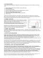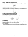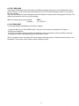
1
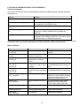
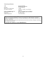
USER MANUAL
Mobeye® Smoke Detector CM2400
Mobeye® Heat Detector CM2400H
SW version 3.n
CONTENT
1.
General description
1
3.
Getting started
Insert a SIM card
Insert the batteries
Enter the program mode
Program at least one telephone number
Mount the GSM module housing to the ceiling
Fix the cover to the GSM module housing
Connect the EI detector and close the cover
Perform a test
Several detectors in a wireless network
2
2
2
2
2
3
3
3
3
4
4.
Use of external power supply
5
5.1
5.2
5.3
5.4
Configuration
Program mode
The (security) code
Programming the settings by SMS
List of SMS commands for configuration
6
6
6
6
7
6.1
6.2
6.3
6.4
6.5
6.6
6.7
Possible settings
Phone numbers
Identification text
Alarm texts
SMS on/off
Call on/off
Test message
System reset
8
8
8
8
8
8
9
9
2.
2.1
2.2
2.3
2.4
2.5
2.6
2.7
2.8
5.
6.
7.
Request list of the settings and status
10
8.
Technical messages and status feedback
11
1. GENERAL DESCRIPTION
This manual is applicable for the Mobeye CM2400 and the Mobeye CM2400H. The CM2400 is a battery
operated GSM module used to send out an alarm after the input is triggered by the EI Electronics smoke
detector EI605TYC.
The CM2400H is a battery operated GSM module used to send out an alarm after the input is triggered
by the EI Electronics heat detector EI603TYC.
In this manual the products are referred to as CM2400(H).
The Mobeye CM2400(H) has following behaviour.
- In case the input of the alarm module is activated by the EI Electronics detector, the Mobeye
CM2400(H) sends an alarm SMS text message and calls to the phone numbers as programmed by the
user.
- In case the batteries need to be replaced, the Mobeye CM2400(H) sends a ‘battery low’ SMS text
message to the administrator.
Please refer to the manual of the EI Electronics detector for the description of the behaviour of the
smoke or heat detector.
1
2. GETTING STARTED
To get started with the Mobeye CM2400(H) at least the following steps need to be taken in following
order:
1.
2.
3.
4.
5.
6.
7.
8.
Place a SIM card (with PIN code 0000 or without PIN code)
Place the batteries
Enter the program mode
Program at least one telephone number (administrators’ number)
Mount the GSM module housing to the ceiling
Fix the cover to the GSM module housing
Connect the EI Electronics detector and close the cover
Perform a test
These steps are further explained in this chapter. After these steps the module will be operational.
NB: in case several EI detectors form a network communicating by RF, at first the TF modules need to
be placed and the detectors need to be enrolled. Please refer to chapter 3.
2.1 INSERT A SIM CARD
Insert a SIM card into the module. Push the black cover outward
slightly to open the holder. Before installing the SIM card should
have PIN code "0000", or PIN code removed.
(A PIN code can be changed or removed by putting the SIM card
in to any mobile phone and entering the 'security' menu)
NB: Make sure the SIM card is inserted before the batteries are
inserted. In case of a SIM card change, please first remove the
batteries (and remove any other external power supply).
2.2 INSERT THE BATTERIES
Insert the two batteries (CR123) in the module. Use the +/- indication for the correct placement. The
green LED will flash to indicate that the module is not configured (at least one telephone number should
be programmed).
2.3 ENTER THE PROGRAM MODE
Directly after inserting the batteries, the Mobeye CM2400(H) switches to the program mode. First the
GSM module establishes network connection. During this time the LED flashes 2 sec. on/1 sec. off.
Within 10-30 seconds the connection is established and the status LED starts flashing 1 sec. on/1 sec.
off (or stays on continuously in case the first telephone number has been configured).
The Mobeye CM2400(H) returns to the program mode by pressing the red button for 5 seconds, until the
LED starts flashing (or stays on continuously).
As long as the unit is in the program mode, the status green LED is on (or flashing 1 sec. on/1 sec. off if
the module has no configuration). During the first 3 minutes, the GSM module remains active, ready to
receive SMS commands. After 3 minutes a time-out occurs and the GSM module switches off in order to
save the batteries. The unit returns to the low power operational mode.
2.4 PROGRAM AT LEAST ONE TELEPHONE NUMBER
The Mobeye CM2400(H) is able to send messages up to 5 telephone numbers. The first telephone
number belongs to the administrator. Technical messages (like battery low) are sent to the administrator
only. Without the administrators’ phone number, the Mobeye CM2400(H) cannot function.
When the CM2400(H) is in initial (factory) status and the batteries are inserted (so the LED is flashing),
the administrators’ number is programmed by calling the telephone number of the Mobeye CM2400(H)
using the administrators’ phone. The unit will recognize this number and store it as administrator
(telephone number 1). The administrator will receive a confirmation SMS text message including the
security code. This code is needed to program the other settings in the unit.
NB: For this way of programming the number recognition in the administrator’s phone must be ‘on’. To
program or change the administrators’ number by SMS command, please refer to 5.2.
2
2.5 MOUNT THE GSM MODULE HOUSING TO THE CEILING
Mount the housing in which the module is fixed to the desired place to the ceiling, using the plugs and
screws. Please refer to the manual of the EI Electronics detector for het ideal location.
2.6 FIX THE COVER TO THE GSM MODULE HOUSING
Take the back cover of the EI Electronics detector. Screw this part to the housing of the GSM module. A
small opening shows the exact place. Lead the green connector through the hole in the back cover. Take
care the cables are not jammed.
2.7 CONNECT THE EI DETECTOR AND CLOSE THE COVER
Press the cabled connector to the pins of the EI Electronics detector. Next to these pins the text 1 2 is
written. Hold the EI detector to prevent tension on the wires!
Close the EI detector by bringing it close to the back cover at the correct position and turn it gently until it
is closed. In the EI detector a red light will flash regularly.
2.8 PERFORM A TEST
After the previous steps, the Mobeye CM2400(H) is in use.
It is armed (switched on) automatically. The green LED on the GSM module blinks once in 3 seconds,
which can only be seen when opening the back cover of the EI detector.
In order to execute a test:
- Press the TEST & HUSH button of the EI detector during a few seconds. The siren will sound and the
GSM module will establish network connection in order to send the SMS messages and call the contact
persons.
3
3. SEVERAL DETECTORS IN A WIRELESS NETWORK
Although the Mobeye CM2400(H) can run as stand-alone unit, it is also possible to form a wireless
network with several EI detectors. For this purpose each EI Electronics detectors needs to be equipped
with an RF module. This module can be integrated in the EI Electronics detector. Before the detectors
are operational, the detectors need to enrolled, in order to know each other.
The placement of the RF modules in the EI Electronics detectors and the enrolment need to be done
before all other steps in chapter 1. Please refer to the EI Electronics manuals for the steps to follow.
4
4. USE OF EXTERNAL POWER SUPPLY
Although the Mobeye CM2400(H) is designed to run on batteries, it is possible to use an external power
supply. In this mode the module is always in connection with the GSM network and therefore always in
program mode. In case the power fails, the batteries take over the functioning and the administrator is
informed by an SMS text message. The module continues operating albeit in the low power mode. This
means the GSM module switches off and only establishes network connection in case it needs to send
out an alarm, test message or low battery alert.
Connect the external power adapter (or any other regulated
12VDC power supply) to the power input of the connector (press
on the green pins for connecting the wires):
- V+ (black lead with white stripe) to “+”
- Ground (black lead) to “-“
5
5. CONFIGURATION
To program the Mobeye CM2400(H), the GSM module must have network connection. In case only
batteries are used, first switch the unit to the program mode. Next send SMS commands for the
configuration.
All settings are stored and will be kept in the unit, even in case the power supplies are removed.
5.1 PROGRAM MODE
Directly after inserting the batteries, the Mobeye CM2400(H) switches to the program mode. First the
GSM module establishes network connection. During this time the LED flashes 2 sec. on/1 sec. off.
Normally this takes 10-30 seconds. Once the connection is established the status LED starts flashing 1
sec. on/1 sec. off (or stays on continuously in case the first telephone number has been configured).
In program mode, the device is ready to receive SMS commands. If no correct command is received for
3 minutes, the GSM module switches off in order to save the batteries. The unit returns to the low power
operational mode. The Mobeye CM2400(H) returns to the program mode by pressing the red button for 5
seconds, until the LED starts flashing (or stays on continuously).
If the unit is connected to an external power supply, the CM2400(H) has network connection all the time
and the unit is in program mode all the time.
5.2 The (security) code
For configuration activities the (security) code of the Mobeye CM2400(H) must be used. The initial
(security) code is ‘1111’. You can change the (security) code to your own code. See section 4.4.
5.3 PROGRAMMING THE SETTINGS BY SMS
To program the settings by SMS text message:
1. Be sure the CM2400(H) is in program mode (please refer to 5.1).
2. Send an SMS message with the (security) code and the command
3. The green LED blinks 3 times to indicate the successful configuration. In case of an incorrect
command, the red LED flashes 5 times.
SMS messages should have the following content: CODE COMMAND:OPTION
- Do not forget the space character between (security) code and command.
- The commands are case sensitive. Use capitals for the commands.
- Several commands may be combined in one SMS message (with a maximum of 160 characters) by
placing a # between the commands.
CODE COMMAND:OPTION#COMMAND:OPTION#COMMAND:OPTION
See section 5.4 for a full list of SMS commands.
6
5.4 LIST OF SMS COMMANDS FOR CONFIGURATION
The setting options for the CM2400(H).
Setting
SMS Command
Change security code
INSTCODE:
Set telephone number for alarm TEL1:
messages
….
TEL5:
Delete telephone number
DEL1
….
DEL5
Identification text
NAME:
Options
0000..9999
Default value
1111
Empty
20 characters
Mobeye
Call on/off
SMS on/off
Alarm text input 1
Interval ‘test SMS’
ON, OFF
ON, OFF
20 characters
0..30 (days)
ON
ON
Fire alarm!
0
CALL:
SMS:
TEXT1:
TEST:
Examples:
Set phone number 1 :
1111 TEL1:0712345678
Delete phone number 1:
1111 DEL1
Be aware of the space between “1111” and the command
7
6. POSSIBLE SETTINGS
6.1 PHONE NUMBERS
The Mobeye CM2400(H) is able to send alarm messages to up to 5 phone numbers. The first telephone
number (TEL1) belongs to the administrator. Only this number receives all system messages. The other
phone numbers (including the administrator) only get the alarm messages.
To set or change telephone numbers:
SMS command 1st telephone number:
example:
TEL1:
1111 TEL1:07123456789
.... similar for TEL2:, TEL3:,TEL4 and TEL5:
For foreign number, start with + followed by the country code (and depending on the country leave out
the zero for the local area code).
example:
1111 TEL1:+447123456789
To delete telephone numbers:
SMS command delete 1st telephone number:
example:
.... similar for DEL2, DEL3, DEL4 and DEL5
DEL1
1111 DEL1
6.2 IDENTIFICATION TEXT
It is possible to add a standard identification text (NAME) to all messages sent out by the Mobeye
CM2400(H). The alarm messages are a combination of the name and the alarm text. A user defined
identification has a length of maximum 20 characters. The default identification text is ‘Mobeye’.
SMS command identification text:
example:
NAME:
1111 NAME:Upstairs
6.3 ALARM TEXTS
A unique alarm text can be programmed into the Mobeye CM2400(H). The user defined text has a
maximum length of 20 characters.
Following default text is programmed:
Text 1 (input 1):
Fire alarm!
SMS command text:
example:
TEXT1:
1111 TEXT2:Fire alarm, get help
6.4 SMS ON/OFF
By default, the Mobeye CM2400(H) sends alarm notifications via text message and calls (you will hear a
beep signal) to the preset contact persons. By turning off the SMS, the unit will only call after a triggered
input.
SMS command enable / disable SMS:
example:
SMS:ON or SMS:OFF
1111 SMS:OFF
6.5 CALL ON/OFF
By default, the Mobeye CM2400(H) sends alarm notifications via text message and calls to the preset
contact persons. By turning off the CALL, the unit will only send an SMS text message as alarm
notification. It is not possible to switch off both the SMS and the call.
SMS command enable / disable call:
example:
CALL:ON or CALL:OFF
1111 CALL:ON
8
6.6 TEST MESSAGE
The Mobeye CM2400(H) can send regular test SMS messages (keep alive) to the administrator (first
phone number), to ensure the proper functioning of the unit. The test message function is only active if
the unit is armed.
The interval between the test messages can be set between 0 days (no test message) and 30 days. The
default test interval is set to 0 (no test message).
SMS command interval test message:
example:
TEST:
1111 TEST:21
6.7 SYSTEM RESET
To reset the Mobeye CM2400(H) to its factory settings:
1. Open the back cover of the GSM module, using the reverse order as explained in chapter 2
2. Remove the batteries
3. Press the red button while reinserting the batteries. Keep it pressed for (about) another 5 seconds
4. Release the button immediately after the LED starts to flash
After a successful reset, the status LED on the keypad will blink green to indicate that the module is not
configured. The security code is back to factory settings as well.
9
7. REQUEST LIST OF THE SETTINGS AND STATUS
The programmed settings and status of the GSM detector can be retrieved by SMS message. Before
sending the request, make sure the unit is in the program mode (please refer to 5.1).
STATUS REQUEST
The status of the Mobeye CM2400(H) can be requested by sending an SMS with the content:
SMS command status request:
example:
STATUS?
1111 STATUS?
Upon sending this request, the Mobeye CM2400(H) returns the status to the originator of the request.
The status message includes the ARMED / NOT CONFIGURED status of the Mobeye CM2400(H), the
status of the inputs, power and batteries.
LIST OF GENERAL SETTINGS
The general settings of the Mobeye CM2400(H) can be requested by sending an SMS with the content :
SMS command list general settings:
example:
SET?
1111 SET?
LIST OF PHONE NUMBERS
The list of telephone numbers can be requested by sending an SMS message with the content :
SMS command list of phone numbers:
example:
CALL?
1111 CALL?
10
8. TECHNICAL MESSAGES AND STATUS FEEDBACK
Technical messages
In the event of technical issues the administrator receives an SMS message. Possible technical
messages are:
Message
Low batteries, external power supply
OK
No external power supply, batteries
OK
Low batteries, no external power
supply
External power supply OK, batteries
OK
(delayed massage)
Reason
Power is available, batteries need to be replaced
No external power supply, batteries are able to take
over operation in low power mode
No external power supply, batteries need to be replaced
The external power is restored (or the adapter is
plugged in a socket), batteries do not need to be
replaced
If (delayed message) is added to the SMS text
messages, the message couldn’t be sent earlier, due to
a SIM card failure or GSM network failure.
When receiving one of the above mentioned technical messages, please take appropriate action as soon
as possible. During the battery replacement, the SIM card does not have to be removed.
Status feedback
LED pattern
Blinking green, 1 second on /
1 second off
1 green flash every 3
seconds
Green LED stays on
continuously
Blinking green,
2 seconds on,
1 second off
Blinking green,
3 seconds on,
1 second off
2 flashes red,
every 3 seconds
Status
Module not configured
Module is switched on,
powered by batteries
Module is switched on,
powered by an external
source
Module establishes network
connection to send an alarm
message
Module establishes network
connection to get to program
mode
No GSM connection
3 flashes red,
every 3 seconds
No valid SIM card or wrong
PIN
Blinking 3 times green
Successful programming
action
Faulty programming action
Blinking 5 times red
4 red flashes
every 3 seconds
Low batteries
Required action
Configure at least one telephone
number
No action required
No action required
Wait until the network connection
is established and the message is
sent
Wait until the network connection
is established before programming
Try the SIM card in any mobile
telephone; replace SIM card using
other telecom provider; try the
module at another location
Try the SIM card in any mobile
telephone; remove PIN code;
check credit; replace SIM card
No action required
Check SMS command
Replace both batteries
11
Technical specifications
GSM
:
Batteries
Battery life in normal mode
Ext. power connection
:
:
:
Power consumption low power
Power consumption 12V
Dimensions
Ambient temperature
:
:
:
:
Quad band EGSM,
850/900/1800/1900 MHz
2* CR123 (lithium)
>1 year
12 VDC (+/- 2 VDC) / min. 500 mA.
(optional)
ca 50 μA. stand-by / max. ca. 500 mA
ca 50 mA. stand-by / max. ca. 500 mA
80 x 60 x 40 mm
-10 °C until +50 °C
This manual is published by Mobeye®.
All rights, the translation included are reserved. Any reproduction, either photocopy, microfilm or
saved in an automated data dictionary, only after written approval of the Publisher. Reprinting, even in
summary, is prohibited.
This user manual meets the technical requirements at the moment of printing. Changes in technology
and equipment are reserved.
© Copyright 2014 by Mobeye, version CM2400EN140701
12
Declaration of Conformity
Herewith we, Mobeye, declare that the product
Mobeye CM21 telemetry module
And the derived products
CM2000, CM2100, CM2200, CM2300,
CM2300FS, CM2400, CM2500, CM2600
are in compliance with the essential requirements of the following European standards /
EU Directives:
Directive 73/23/EEC (low voltage directive)
Directive IEC/EN 50130 Electromagnetic compatibility
Directive 1995/5/EC R&TTE (Radio & Telecommunications Terminal Equipment)
The conformity with the essential requirements of 1995/5/EC has been verified against:
ETSI EN 301 489-1 V1.5.1
ETSI EN 301 489-7 V1.2.1
ETSI EN 301 511 V9.0.2
CENELEC EN 60950:2001
Mobeye B.V., Poeldonkweg 5, 5216 JX ’s-Hertogenbosch, The Netherlands
13