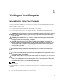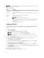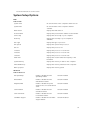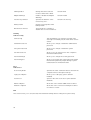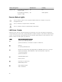
1
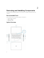
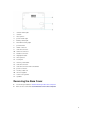
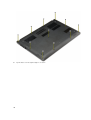
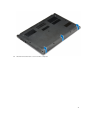
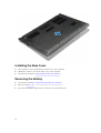
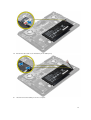
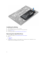
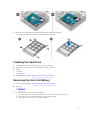
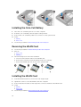
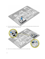
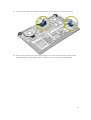
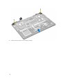
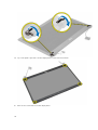
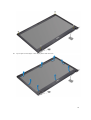
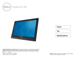
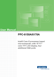
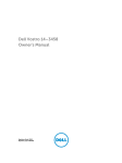
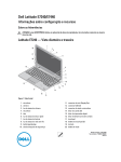
Dell Vostro 5480
Owner's Manual
Regulatory Model: P41G
Regulatory Type: P41G002
Notes, Cautions, and Warnings
NOTE: A NOTE indicates important information that helps you make better use of your computer.
CAUTION: A CAUTION indicates either potential damage to hardware or loss of data and tells you
how to avoid the problem.
WARNING: A WARNING indicates a potential for property damage, personal injury, or death.
Copyright © 2015 Dell Inc. All rights reserved. This product is protected by U.S. and international copyright and
intellectual property laws. Dell™ and the Dell logo are trademarks of Dell Inc. in the United States and/or other
jurisdictions. All other marks and names mentioned herein may be trademarks of their respective companies.
2014 - 12
Rev. A00
Contents
1 Working on Your Computer................................................................................5
Before Working Inside Your Computer................................................................................................ 5
Turning Off Your Computer..................................................................................................................6
After Working Inside Your Computer................................................................................................... 7
2 Removing and Installing Components............................................................. 8
Recommended Tools............................................................................................................................8
System Overview................................................................................................................................... 8
Removing the Base Cover.....................................................................................................................9
Installing the Base Cover.....................................................................................................................12
Removing the Battery..........................................................................................................................12
Installing the Battery............................................................................................................................14
Removing the Hard Disk Drive............................................................................................................14
Installing the Hard Drive...................................................................................................................... 15
Removing the Coin-Cell Battery.........................................................................................................15
Installing the Coin-Cell Battery...........................................................................................................16
Removing the WLAN Card.................................................................................................................. 16
Installing the WLAN Card.................................................................................................................... 16
Removing the System Fan................................................................................................................... 17
Installing the System Fan.................................................................................................................... 20
Removing the Heatsink.......................................................................................................................20
Installing the Heatsink......................................................................................................................... 21
Removing the Memory Module.......................................................................................................... 21
Installing the Memory......................................................................................................................... 22
Removing the System Board.............................................................................................................. 22
Installing the System Board................................................................................................................ 24
Removing the Display Assembly.........................................................................................................24
Installing the Display Assembly...........................................................................................................27
Removing the Display Bezel............................................................................................................... 27
Installing the Display Bezel................................................................................................................. 30
Removing the Display Panel............................................................................................................... 30
Installing the Display Panel..................................................................................................................31
Removing the Camera.........................................................................................................................31
Installing the Camera.......................................................................................................................... 32
3 System Setup....................................................................................................... 33
System Setup Overview...................................................................................................................... 33
Boot Sequence.................................................................................................................................... 33
Navigation Keys................................................................................................................................... 33
Updating the BIOS ..............................................................................................................................34
System Setup Options.........................................................................................................................35
4 Troubleshooting................................................................................................. 37
Enhanced Pre-Boot System Assessment (ePSA) Diagnostics............................................................37
Battery Status Lights............................................................................................................................ 37
Device Status Lights............................................................................................................................ 38
LED Error Codes..................................................................................................................................38
5 Specifications...................................................................................................... 40
Technical Specification.......................................................................................................................40
6 Contacting Dell...................................................................................................45
Contacting Dell................................................................................................................................... 45
Working on Your Computer
1
Before Working Inside Your Computer
Use the following safety guidelines to help protect your computer from potential damage and to help to
ensure your personal safety. Unless otherwise noted, each procedure included in this document assumes
that the following conditions exist:
•
You have read the safety information that shipped with your computer.
•
A component can be replaced or--if purchased separately--installed by performing the removal
procedure in reverse order.
WARNING: Disconnect all power sources before opening the computer cover or panels. After you
finish working inside the computer, replace all covers, panels, and screws before connecting to
the power source.
WARNING: Before working inside your computer, read the safety information that shipped with
your computer. For additional safety best practices information, see the Regulatory Compliance
Homepage at www.dell.com/regulatory_compliance
CAUTION: Many repairs may only be done by a certified service technician. You should only
perform troubleshooting and simple repairs as authorized in your product documentation, or as
directed by the online or telephone service and support team. Damage due to servicing that is
not authorized by Dell is not covered by your warranty. Read and follow the safety instructions
that came with the product.
CAUTION: To avoid electrostatic discharge, ground yourself by using a wrist grounding strap or
by periodically touching an unpainted metal surface, such as a connector on the back of the
computer.
CAUTION: Handle components and cards with care. Do not touch the components or contacts
on a card. Hold a card by its edges or by its metal mounting bracket. Hold a component such as a
processor by its edges, not by its pins.
CAUTION: When you disconnect a cable, pull on its connector or on its pull-tab, not on the cable
itself. Some cables have connectors with locking tabs; if you are disconnecting this type of cable,
press in on the locking tabs before you disconnect the cable. As you pull connectors apart, keep
them evenly aligned to avoid bending any connector pins. Also, before you connect a cable,
ensure that both connectors are correctly oriented and aligned.
NOTE: The color of your computer and certain components may appear differently than shown in
this document.
To avoid damaging your computer, perform the following steps before you begin working inside the
computer.
1.
Ensure that your work surface is flat and clean to prevent the computer cover from being scratched.
2.
Turn off your computer (see Turning off Your Computer).
5
3.
If the computer is connected to a docking device (docked), undock it.
CAUTION: To disconnect a network cable, first unplug the cable from your computer and
then unplug the cable from the network device.
4.
Disconnect all network cables from the computer.
5.
Disconnect your computer and all attached devices from their electrical outlets.
6.
Close the display and turn the computer upside-down on a flat work surface.
NOTE: To avoid damaging the system board, you must remove the main battery before you
service the computer.
7.
Remove the main battery.
8.
Turn the computer top-side up.
9.
Open the display.
10. Press the power button to ground the system board.
CAUTION: To guard against electrical shock, always unplug your computer from the
electrical outlet before opening the display.
CAUTION: Before touching anything inside your computer, ground yourself by touching an
unpainted metal surface, such as the metal at the back of the computer. While you work,
periodically touch an unpainted metal surface to dissipate static electricity, which could
harm internal components.
11. Remove any installed ExpressCards or Smart Cards from the appropriate slots.
Turning Off Your Computer
CAUTION: To avoid losing data, save and close all open files and exit all open programs before
you turn off your computer.
1.
Shut down the operating system:
•
Windows 8:
– Point to upper-right corner of the screen and click Settings. Click on the
Shut down.
•
and then select
In Windows 7:
1.
Click Start
.
2.
Click Shut Down.
3.
or
2.
6
1.
Click Start
.
2.
Click the arrow in the lower-right corner of the Start menu as shown below, and then click
Shut Down..
Ensure that the computer and all attached devices are turned off. If your computer and attached
devices did not automatically turn off when you shut down your operating system, press and hold
the power button for about 4 seconds to turn them off.
After Working Inside Your Computer
After you complete any replacement procedure, ensure you connect any external devices, cards, and
cables before turning on your computer.
CAUTION: To avoid damage to the computer, use only the battery designed for this particular
Dell computer. Do not use batteries designed for other Dell computers.
1.
Connect any external devices, such as a port replicator or media base, and replace any cards, such as
an ExpressCard.
2.
Connect any telephone or network cables to your computer.
CAUTION: To connect a network cable, first plug the cable into the network device and then
plug it into the computer.
3.
Replace the battery.
4.
Connect your computer and all attached devices to their electrical outlets.
5.
Turn on your computer.
7
Removing and Installing Components
This section provides detailed information on how to remove or install the components from your
computer.
Recommended Tools
The procedures in this document may require the following tools:
•
•
•
Small flat-blade screwdriver
Phillips screwdriver
Small plastic scribe
System Overview
8
2
1.
camera-status light
2.
camera
3.
microphone
4.
power-status light
5.
battery-status light
6.
hard-drive activity light
7.
power button
8.
HDMI connector
9.
USB 3.0 connector
10. network connector
11.
headset connector
12. fingerprint reader
13. microphones
14. touchpad
15. memory card reader
16. USB 3.0 connector
17. USB 3.0 connector with PowerShare
18. power connector
19. security-cable slot
20. service-tag label
21. sub-woofer speaker
22. speakers
Removing the Base Cover
1.
Follow the procedures in Before Working Inside Your Computer.
2.
Remove the screws that secure the base cover to the computer.
9
3.
10
Pry the base cover along the edges to loosen it.
4.
Lift and remove the base cover from the computer.
11
Installing the Base Cover
1.
Place the base cover to align with the screw holes on the computer.
2.
Tighten the screws to secure the base cover to the computer.
3.
Follow the procedures in After Working Inside Your computer.
Removing the Battery
1.
Follow the procedures in Before Working Inside Your Computer.
2.
Remove the base cover.
3.
Disconnect the battery cable from its connector on the system board.
12
4.
Release the tabs that secure the battery in the battery bay.
5.
Lift and remove the battery from the computer.
13
Installing the Battery
1.
Place the battery into its slot on the computer.
2.
Connect the battery cable to its connector on the system board.
3.
Install the base cover.
4.
Follow the procedures in After Working Inside Your computer.
Removing the Hard Disk Drive
1.
Follow the procedures in Before Working Inside Your Computer.
2.
Remove :
a. base cover
b. battery
3.
14
Lift the hard drive assembly in an upward direction to release it from its compartment on the
computer. Remove the hard drive from the computer.
4.
Remove the screws that secure the hard drive to the hard drive assembly.
a. Lift and remove the hard drive from the hard drive assembly.
Installing the Hard Drive
1.
Place the hard drive assembly into its slot on the computer.
2.
Tighten the screw that secures the hard drive to the computer
3.
Install:
a. battery
b. base cover
4.
Follow the procedures in After Working Inside Your computer
Removing the Coin-Cell Battery
1.
Follow the procedures in Before Working Inside Your Computer.
2.
Remove :
a. base cover
b. battery
3.
Perform the steps as shown in the illustration:
a. Disconnect the coin-cell battery cable from its connector on the system board.
b. Unroute the coin-cell battery cable from the routing channel.
c. Lift and remove the coin-cell from the computer.
15
Installing the Coin-Cell Battery
1.
Place the coin-cell battery into its slot on the computer.
2.
Route the coin-cell battery cable along the routing channel.
3.
Connect the coin-cell battery cable to its connector on the system board.
4.
Install :
a. battery
b. base cover
5.
Follow the procedures in After Working Inside Your computer
Removing the WLAN Card
1.
Follow the procedures in Before Working Inside Your Computer.
2.
Remove:
a. base cover
b. battery
3.
Perform the steps as shown in the illustration:
a. Disconnect the antenna cable from the WLAN card.
b. Remove the screw that secures the WLAN card to the computer.
c. Remove the WLAN card from its slot on the system board.
Installing the WLAN Card
1.
Insert the WLAN card into its connector at a 45–degree angle.
2.
Tighten the screw to secure the WLAN card to the computer.
3.
Connect the antenna cables to their respective connectors marked on the WLAN card.
4.
Install:
a. battery
b. base cover
5.
16
Follow the procedures in After Working Inside Your computer.
Removing the System Fan
1.
Follow the procedures in Before Working Inside Your Computer.
2.
Remove:
a. base cover
b. battery
3.
Perform the steps as shown in the illustration:
a. Disconnect the left system fan cable from its connector on the system board.
b. Remove the screws that secure the left system fan to the system board.
4.
Lift and remove the left system fan from the computer.
17
5.
Disconnect the right system fan cable from its connector on the system board. Peel away the system
board flex cable from the right system fan.
6.
Remove the screws that secure the right system fan to the system board.
18
7.
Lift and remove the right system fan from the computer.
19
Installing the System Fan
1.
Place the right system fan into its original position in the system board and affix the system board flex
cable.
2.
Tighten the screws that secure the right system fan to the system board.
3.
Connect the right system fan cable to its connector on the system board.
4.
Place the left system fan into its original position in the system board.
5.
Tighten the screws that secure the left system fan to the system board.
6.
Connect the left system fan cable to its connector on the system board.
7.
Install :
a. battery
b. base cover
8.
Follow the procedures in After Working Inside Your computer.
Removing the Heatsink
1.
Follow the procedures in Before Working Inside Your Computer.
2.
Remove:
a. base cover
b. battery
c. system fan
3.
Remove the screws that secure the heatsink to the system board.
4.
Lift up the heatsink and remove from the computer.
20
Installing the Heatsink
1.
Place the heatsink into its original position on the system board.
2.
Tighten the screws to secure the heatsink to the system board.
3.
Install:
a. system fan
b. battery
c. base cover
4.
Follow the procedures in After Working Inside Your computer
Removing the Memory Module
1.
Follow the procedures in Before Working Inside Your Computer.
2.
Remove:
a.
b.
c.
d.
3.
base cover
battery
system fan
heatsink
Pry the retention clips away from the memory module until it pops up. Remove the memory module
from its connector on the system board.
21
Installing the Memory
1.
Insert the memory module into the memory socket.
2.
Press the memory module down until it clicks into place.
3.
Install:
a.
b.
c.
d.
4.
heatsink
system fan
battery
base cover
Follow the procedures in After Working Inside Your computer.
Removing the System Board
1.
Follow the procedures in Before Working Inside Your Computer.
2.
Remove :
a.
b.
c.
d.
e.
3.
Disconnect the following cables:
a.
b.
c.
d.
e.
22
base cover
battery
system fan
heatsink
memory
speaker
display
keyboard
touchpad
camera
4.
Remove the screws that secure the system board to the chassis.
5.
Remove the system board from the computer.
23
Installing the System Board
1.
Place the system board into its original position on the chassis.
2.
Install the screws that secure the system board to the chassis.
3.
Connect :
a.
b.
c.
d.
e.
4.
Install :
a.
b.
c.
d.
e.
5.
camera cable
touchpad cable
keyboard cable
display cable
speaker cable
memory
heatsink
system fan
battery
base cover
Follow the procedures in After Working Inside Your computer
Removing the Display Assembly
1.
Follow the procedures in Before Working Inside Your Computer.
2.
Remove :
a. base cover
b. battery
24
3.
Disconnect the LVDS cable and the camera cable from its connectors on the system board.
4.
Remove the screws that secure the display hinges to the system board. Lift and move the system
base panel away from the display hinges to facilitate easy removal of the display assembly.
25
5.
26
Detach the base panel from the display assembly..
Installing the Display Assembly
1.
Align the base panel of the computer to the display hinges.
2.
Install the screws that secure the display hinges to the base panel
3.
Connect the LVDS cable and the camera cable to the connectors on the system board.
4.
Install :
a. battery
b. base cover
5.
Follow the procedures in After Working Inside Your computer
Removing the Display Bezel
1.
Follow the procedures in Before Working Inside Your Computer.
2.
Remove :
a. base cover
b. battery
c. display assembly
3.
Rotate the hinge brackets at the angle shown to facilitate easy removal of the display bezel.
27
4.
Pry on the plastic caps that cover the display bezel screws and remove them.
5.
Remove the screws that secure the display bezel.
28
6.
Pry along the inner edges of the display bezel and remove it.
29
Installing the Display Bezel
1.
Align the display bezel by pressing along the edges.
2.
Install the screws that secure the display bezel.
3.
Install the plastic caps that secure the display bezel screws on both sides of the display bezel.
4.
Install :
a. battery
b. base cover
c. display assembly
5.
Follow the procedures in After Working Inside Your computer.
Removing the Display Panel
1.
Follow the procedures in Before Working Inside Your Computer.
2.
Remove:
a.
b.
c.
d.
base cover
battery
display assembly
display bezel
3.
Remove the screws that secure the display panel to the display assembly.
4.
Lift and remove the display panel from the display assembly.
30
Installing the Display Panel
1.
Align the display panel to the display assembly by pressing along the edges.
2.
Install the screws that secure the display panel.
3.
Install:
a.
b.
c.
d.
4.
battery
base cover
display assembly
display bezel
Follow the procedures in After Working Inside Your computer.
Removing the Camera
1.
Follow the procedures in Before Working Inside Your Computer.
2.
Remove :
a.
b.
c.
d.
e.
3.
base cover
battery
display assembly
display bezel
display
Disconnect the camera cable and lift the camera to remove it from the computer.
31
Installing the Camera
1.
Align the camera to the display panel .
2.
Connect the camera cable to the camera.
3.
Install :
a.
b.
c.
d.
e.
4.
32
battery
base cover
display assembly
display bezel
display
Follow the procedures in After Working Inside Your computer
System Setup
3
System Setup Overview
System Setup allows you to:
•
•
•
•
change the system configuration information after you add, change, or remove any hardware in your
computer.
set or change a user-selectable option such as the user password.
read the current amount of memory or set the type of hard drive installed.
check battery health.
Before you use System Setup, it is recommended that you write down the System Setup screen
information for future reference.
CAUTION: Unless you are an expert computer user, do not change the settings for this program.
Certain changes can cause your computer to work incorrectly.
Boot Sequence
Boot Sequence allows you to bypass the System Setup‐defined boot device order and boot directly to a
specific device (for example: optical drive or hard drive). During the Power-on Self Test (POST), when the
Dell logo appears, you can:
•
•
Access System Setup by pressing <F2> key
Bring up the one-time boot menu by pressing <F12> key
The one-time boot menu displays the devices that you can boot from including the diagnostic option.
The boot-menu options are:
•
•
Removable Drive (if available)
STXXXX Drive
NOTE: XXX denotes the SATA drive number.
•
•
Optical Drive
Diagnostics
NOTE: Choosing Diagnostics, will display the ePSA diagnostics screen.
The boot sequence screen also displays the option to access the System Setup screen.
Navigation Keys
The following table displays the system setup navigation keys.
33
NOTE: For most of the system setup options, changes that you make are recorded but do not take
effect until you re-start the system.
Table 1. Navigation Keys
Keys
Navigation
Up arrow
Moves to the previous field.
Down arrow
Moves to the next field.
<Enter>
Allows you to select a value in the selected field (if applicable) or follow the link in
the field.
Spacebar
Expands or collapses a drop‐down list, if applicable.
<Tab>
Moves to the next focus area.
NOTE: For the standard graphics browser only.
<Esc>
Moves to the previous page till you view the main screen. Pressing <Esc> in the main
screen displays a message that prompts you to save any unsaved changes and
restarts the system.
<F1>
Displays the System Setup help file.
Updating the BIOS
It is recommended to update your BIOS (system setup), on replacing the system board or if an update is
available. For laptops, ensure that your computer battery is fully charged and connected to a power
outlet
1.
Re-start the computer.
2.
Go to dell.com/support.
3.
Enter the Service Tag or Express Service Code and click Submit.
NOTE: To locate the Service Tag, click Where is my Service Tag?
NOTE: If you cannot find your Service Tag, click Detect My Product. Proceed with the
instructions on screen.
4.
If you are unable to locate or find the Service Tag, click the Product Category of your computer.
5.
Choose the Product Type from the list.
6.
Select your computer model and the Product Support page of your computer appears.
7.
Click Get drivers and click View All Drivers.
The Drivers and Downloads page opens.
8.
On the Drivers and Downloads screen, under the Operating System drop-down list, select BIOS.
9.
Identify the latest BIOS file and click Download File.
You can also analyze which drivers need an update. To do this for your product, click Analyze
System for Updates and follow the instructions on the screen.
10. Select your preferred download method in the Please select your download method below window,
click Download File.
The File Download window appears.
11. Click Save to save the file on your computer.
12. Click Run to install the updated BIOS settings on your computer.
34
Follow the instructions on the screen.
System Setup Options
Main
Table 2. Main
System Time
Re-sets the time on the computer's internal clock.
System Date
Re-sets the date on the computer's internal
calendar.
BIOS Version
Displays the BIOS revision.
Product Name
Displays the product name and the model number.
Service Tag
Displays the service tag of your computer.
Asset Tag
Displays the asset tag of your computer (if
available).
CPU Type
Displays the type of processor.
CPU Speed
Displays the speed of the processor.
CPU ID
Displays the processor ID.
L1 Cache
Displays the processor L1 cache size.
L2 Cache
Displays the processor L2 cache size.
L3 Cache
Displays the processor L3 cache size.
Fixed HDD
Displays the model number and capacity of the
hard drive.
System Memory
Displays the memory in-built on the computer.
Extended Memory
Displays the memory installed on the computer.
Memory Speed
Displays the memory speed.
Advanced
Table 3. Advanced
Intel SpeedStep
Enable or disable the Intel
SpeedStep feature.
Default: Enabled
Virtualization
Enable or disable the Intel
Virtualization feature.
Default: Enabled
Integrated NIC
Enable or disable the power
supply to the on–board network
card.
Default: Enabled
USB Emulation
Enable or disable the USB
emulation feature.
Default: Enabled
USB PowerShare
Enable or disable the USB
PowerShare feature.
Default: Enabled
USB Wake Support
Enable or disable the USB wake
support feature
Default: Disabled
35
SATA Operation
Change the SATA controller
mode to either ATA or AHCI.
Default: AHCI
Adapter Warnings
Enable or disable the Adapter
Warnings.
Default: Enable
Function Key Behavior
Specifies the behavior of the
function key <Fn>.
Default: Function key
Battery Health
Displays a message about the
battery health.
Miscellaneous Devices
These fields let you enable or
disable various on-board devices.
Security
Table 4. Security
Set Asset Tag
This field displays your system's asset tag. If the
asset tag is not already set, this field can be used to
enter it.
Set Admin Password
Allows you to change or delete the administrator
password.
Set System Password
Allows you to change or delete the system
password.
Set HDD Password
Allows you to set a password on the computer's
internal hard drive (HDD).
Password Change
Allows you to change the security password.
Password Bypass
Allows you to bypass the system password and the
internal HDD password prompts during a system
restart/resume from hibernate state.
Boot
Table 5. Boot
Boot Priority Order
Specifies the order of different devices in which the
computer will boot through at start up.
Legacy Boot Option
Allows you to load legacy option. (Default:
Enabled)
Secure Boot
Species if the UEFI secure boot option (Default:
Disabled)
Add Boot Option
Allows the user to add an additional boot device.
Delete Boot Option
Allows the user to remove an existing boot device
from the boot order.
Exit
This section allows you to save, discard, and load default settings before exiting from System Setup.
36
4
Troubleshooting
Enhanced Pre-Boot System Assessment (ePSA)
Diagnostics
The ePSA diagnostics (also known as system diagnostics) performs a complete check of your hardware.
The ePSA is embedded with the BIOS and is launched by the BIOS internally. The embedded system
diagnostics provides a set of options for particular devices or device groups allowing you to:
•
Run tests automatically or in an interactive mode
•
Repeat tests
•
Display or save test results
•
Run thorough tests to introduce additional test options to provide extra information about the failed
device(s)
•
View status messages that inform you if tests are completed successfully
•
View error messages that inform you of problems encountered during testing
CAUTION: Use the system diagnostics to test only your computer. Using this program with other
computers may cause invalid results or error messages.
NOTE: Some tests for specific devices require user interaction. Always ensure that you are present
at the computer terminal when the diagnostic tests are performed.
1.
Power-on the computer.
2.
As the computer boots, press the <F12> key as the Dell logo appears.
3.
On the boot menu screen, select the Diagnostics option.
The Enhanced Pre-boot System Assessment window is displayed, listing all devices detected in the
computer. The diagnostics starts running the tests on all the detected devices.
4.
If you wish to run a diagnostic test on a specific device, press <Esc> and click Yes to stop the
diagnostic test.
5.
Select the device from the left pane and click Run Tests.
6.
If there are any issues, error codes are displayed.
Note the error code and contact Dell.
Battery Status Lights
Table 6. Battery LED Behavior
Battery Charge LED
Off/Hibernate
Standby
AC mode
Full charge
Off
Off
Charging
Solid White
Solid White
37
Battery Charge LED
Off/Hibernate
Standby
Battery mode
Discharging when Battery
charge is > 10%
Off
Off
Discharging when Battery
charge is <=10%
Off
Blinking White
Device Status Lights
Turns on when you turn on the computer and blinks when the computer is in a power
management mode.
Turns on when the computer reads or writes data.
Turns on steadily or blinks to indicate battery charge status.
LED Error Codes
Diagnostic LED codes are communicated via the Power Button LED. The Power Button LED blinks the
corresponding LED codes for the corresponding fault condition. Example: For No Memory detected (LED
code 2) , The Power Button LED blinks two times followed by a pause, blinks two times, pause, etc. This
pattern continues until the system is powered off.
Code
Cause and Troubleshooting Steps
1
System board: BIOS ROM failure
System board failure, covers BIOS corruption or ROM error
2
Memory
No memory/RAM detected
3
Chipset Error (North and South Bridge Chipset, DMA/IMR/ Timer Error) , Time-OfDay Clock test failure , Gate A20 failure , Super I/O chip failure , Keyboard
controller test failure
System board failure
4
RAM Read/Write failure
Memory failure
5
Real-time clock power fail
CMOS battery failure
6
Video BIOS test failure
Video card failure
38
Code
Cause and Troubleshooting Steps
7
CPU - cache test failure
Processor failure
8
Display
Display failure
39
5
Specifications
Technical Specification
NOTE: Offerings may vary by region. For more information regarding the configuration of your
(Start icon) → Help and Support, and then select the option to view
computer, click Start
information about your computer.
NOTE: In Windows 8, navigate to Help and Support to view information about your computer.
Table 7. System Information
Feature
Description
Chipset
Intel i3, i5, i7 Series
DRAM bus width
64–bit
Flash EPROM
W25Q64FVSSIQ
Table 8. Processor
Feature
Description
L3 smart cache
3 MB and 4 MB
Table 9. Memory
Feature
Description
Memory connector
HM87
Memory capacity
8 GB
Memory type
DDRL, SO-DIMM
Memory Controller
Broadwell U
Minimum memory
4 GB
Maximum memory
8 GB
Table 10. Audio
Feature
Description
Type
two 1.5 watt speakers and one 2 watt subwoofer
Controller
Realtek ALC290Q
40
Feature
Description
Internal microphone supports
Digital microphone x 2
Speakers
3
Volume controls
Program menus and keyboard shortcut keys
Table 11. Video
Feature
Description
Video type
UMA/DIS
Video Controller:
UMA
Intel HD graphics 5x00
Discrete
Nvidia N15S-GM
Data bus
64–bit
External display support
HDMI
Table 12. Camera
Feature
Description
Camera Resolution
1 Megapixel
Video Resolution (maximum)
1280 x 720 pixels
Diagonal viewing angle
74–degree
Table 13. Communication
Feature
Description
Network adapter
Ethernet 10/100/1000 Base-T
Wireless
w-fi 802.11 agn/ac
Table 14. Ports and Connectors
Feature
Description
Audio
combo jack
Video
HDMI
Network adapter
RJ–45
USB
two USB 3.0, one USB 3.0 PowerShare port
Media card reader
SD
41
Table 15. Display
Feature
Description
Type
HD
Dimensions:
Height
206.44 mm (8.12 inches)
Width
326.18 mm (12.84 inches)
Diagonal
14.0"
Active area (X/Y)
309.4 mm (12.18 inches) x
173.95 mm (6.84 inches)
Maximum resolution
1366 x 768 pixels
Maximum Brightness
200 nits
Operating angle
135–degree
Refresh rate
60Hz /40Hz
Minimum Viewing angles:
Horizontal
40(L)/40( R)
Vertical
10(up)/30(down)
Pixel pitch
0.2265 (H) x 0.2265 (V)
mm
Table 16. Keyboard
Feature
Description
Number of keys
80
Table 17. Touchpad
Feature
Description
Active Area:
X-axis
111.40 mm (4.38 inches)
Y-axis
76.40 mm (3 inches)
Table 18. Battery
Feature
Description
Type
ICP666480
Dimensions:
42
Height
99.5 mm (3.91 inches)
Width
198.5 mm (7.81 inches)
Depth
7.5 mm (0.30 inch)
Feature
Weight
Description
269 grams (0.60 lb)
Charge time
3 hour
Voltage
11.4 V
Temperature range:
Operating
0 ℃ to 50 ℃
Non-Operating
0 ℃ to 65 ℃
Coin-cell battery
LI 3V 83 MAH
Table 19. AC Adapter
Feature
Description
Type
AC adapter
Input voltage
90 ~ 264 VAC
Input current (maximum)
1.6 A / 1.5 A
Input frequency
50 Hz–60 Hz
Output power
65 W
Output current
0 A to 3.34 A
Rated output voltage
19.5 V
Temperature range:
Operating
0 ℃ to 40 ℃
Non-Operating
95 ℃
Table 20. Physical
Feature
Non-Touch
Touch
Height
18.30 mm (0.72 inch)
19.35 mm (0.76 inch)
Width
337.60 mm (13.29 inches)
337.60 mm (13.29 inches)
Depth
233.50 mm (9.19 inch)
233.50 mm (9.19 inch)
Weight (minimum)
1.53 kg (3.37 lb)
1.62 kg (3.57 lb)
Table 21. Environmental
Feature
Description
Temperature:
Operating
0 ℃ to 35 ℃
Storage
-20 ℃ to 60 ℃
Relative humidity (maximum):
43
Feature
Description
Operating
20% – 90%
Storage
20% – 95%
Altitude (maximum):
Operating
–15.2 m to 3048 m (–50 to 10,000 ft)
0° to 35°C
44
Non-Operating
–15.2 m to 10,668 m (–50 ft to 35,000 ft)
Airborne contaminant level
G2 or lower as defined by ISA - S71.04 – 1985
Contacting Dell
6
Contacting Dell
NOTE: If you do not have an active Internet connection, you can find contact information on your
purchase invoice, packing slip, bill, or Dell product catalog.
Dell provides several online and telephone-based support and service options. Availability varies by
country and product, and some services may not be available in your area. To contact Dell for sales,
technical support, or customer service issues:
1.
Go to dell.com/support.
2.
Select your support category.
3.
Verify your country or region in the Choose a Country/Region drop-down list at the bottom of the
page.
4.
Select the appropriate service or support link based on your need.
45