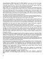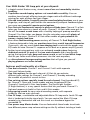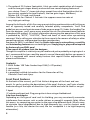
1
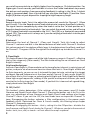
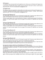
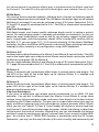
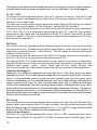
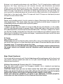
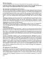
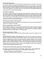
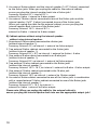
RAIDER 100
Tube Guitar Amplifier
Operator´s Manual
Please, first read this manual carefully!
Tube
Amp
Technology
Table of Contents
Introduction
Features and Functionality at a Glance
Contents
Front Panel Features:
Input; Channel 1 Control Features
Power Amp section: Presence, Depth Punch, P.T.M. Display
Channel 2 Control Features, Mid Boost
Power Amp section: Master A/B
Channel selection, Hi Gain, FX Loop
Stand By, Power
page:
4
4, 5
6
6-8
9
10
10 - 12
12
13
Rear Panel Features:
Mains, Mains Fuse
S.A.C. Port for Z-9, Footswitch Ports
Noise Gate: Threshold Level
Main FX Loop: Send, Return, and Balance
Serial FX Loop: Send, Return
Poweramp Output 4, 8 16 Ohms
Poweramp Output: speaker options
13
14, 15
15, 16
16
16, 17
17
17, 18
Handling and Care
Troubleshooting
Important note concerning the cooling fans
Technical Data, Detailed Specifications and Ratings
Tube Map, Tube Exchange Service
Remote Control Options
Wiring of Principal Connectors
Front Panel Diagrams for Noting Settings
Configuration table for Z-9 settings
19
20, 21
21
22
23
24
24
25
26
CAUTION! Please read and heed the following:
You'll find an ancillary pamphlet accompanying this owner's manual entitled
Instructions for the Prevention of Fire, Electrical Shock and Injury. Be sure to read it
before you plug in and power up the amp!
Note: Technical specifications are subject to change without notice.
3
Congratulations, ENGL Amp user! The ENGL Raider is one mean machine of a tubedriven guitar amplifier, engineered to inspire you and enthuse your audience.
Alongside to-die-for tone, it puts at your fingertips everything you need to tap your
creative potential and make your musical message heard and felt!
When yours truly, a humble ENGL amp designer by profession, developed the ENGL
Raider 100 amp, two goals loomed large in my mind. I aimed to pair tonal perfection
with useful features that make sound (pun intended) sense in the real world. Out
came a new type of design – a nifty combination of two primary channels 1 and 2, each
with different gain structures, and two gain stages. That adds up to four different
basic sounds ranging from clean to hi gain lead. Best of all, you can dial in just about
any flavor of crunch in between, quickly and easily.
To broaden the tonal palette and afford you even greater sound-sculpting flexibility, I
endowed the Raider's preamp section with a fresh, new Mid Boost button. Have fun
mixing and matching its two settings with any of the four gain stages.
With so many options to choose from on the fly, you enjoy instant access to
painstakingly tuned, tonally balanced sounds that will serve you well for many styles
and playing techniques. Lead sounds with a mighty midrange punch, lean-and-mean
rhythm guitar tones, or heavy-duty low end for power chord riffing – you'll find your
amp delivers all this and a lot more. And Channel 1 sports innovative brightness
boosting circuits designed to accentuate this channel's tonal nuances.
Here's how this works: One Bright button affects both of Channel 1's Lo and Hi Gain
stages, and another special Clean Bright button affects Channel 1's Lo Gain stage only.
Engage it to conjure sparkling clean sounds. On top of this, you get a button that lets
you determine if the two power amp voicing knobs Presence and Depth Punch shape
the power amp's frequency response for Channel 1. The alternative is to have a
precision-tuned, hardwired EQ filtering circuit shape the power amp's response when
Channel 1 is active.
A/B Master switching is a powerful option that has proven its merits in countless ENGL
amps (it was featured in E920 power amps since the late '80s and in the legendary
SAVAGE 120 head since '93!). Your Raider Combo also sports two effect loops and a
high quality spring reverb system to round out its arsenal of sound-shaping tools.
The tonal palette ranges from vintage clean to classic grind, and from creamy rock lead
tone with thick, lush tube overdrive to the kind of massive hi-gain lead sound it takes to
cut through in appropriate playing situations.
And there's more: This amp sports our Serial Amp Control Port, or S.A.C. Port for short.
Plug an ENGL Z-9 Custom Foot Controller into to it and get hip to some very convenient
remote control options. This footboard lets you activate the two channels in
combination with the Hi Gain option and Master A/B switching directly simply by
tapping its four footswitches. And that affords you instant access to four sound
variations at four different volume levels.
In addition, the amp comes with three stereo jacks designed to accept dual
footswitches like the ENGL Z-4 or a MIDI switching system (e.g. ENGL Z-11) for
selecting the channels and other crucial Amp features.
The exterior's compelling visuals certainly match the interior's impressive
appointments. This amp's elegant and stylish look is sure to turn heads wherever you
play.
4
Your ENGL Raider 100 Amp puts at your disposal:
1. a logical control feature array, utmost ease of use and remarkably intuitive
handling;
2. Top-drawer sound-shaping options and remarkable versatility: You can
combine two channels offering two gain stages each with different midrange
voicings for each of these four gain stages.
3. A broad tonal palette: Surgically precise sound-sculpting functions are at your
fingertips, and a tap of your foot on the conveniently compact footboard gives
you some very powerful remote control options.
4. Four first-rate fundamental sounds in glorious all-tube tone: Channel 1 Lo Gain
takes you from clean to a touch of mean. Channel 1 Hi Gain adds some grit to
the mill for sweet crunch tones with a healthy helping of preamp overdrive.
Channel 2 Lo Gain takes you deeper into the saturation zone with plenty of
headroom to spare. Channel 2 Hi Gain offers oodles of gain potential for
creamy, singing lead tone.
5. Even more tone-tweaking power courtesy of Channel 1's Dual Bright button,
a feature designed to help you precision-tune those crucial top-end frequencies.
If you wish, you can use an extra tone-shaping tool to activate the power amp
EQ knobs to voice Channel 1's response or fall back on a power amp EQ preset.
6. further tone-tuning options such as an onboard reverb system featuring
dedicated controls for each of the two main channels and a long Reverb
spring that conjures lush, deep and warm reverb, as well as two effect loops
that let you factor multi-effect processors into the sonic equation;
7. an ultra-advanced tone-generating machine that will give you years of
playing pleasure and value to boot.
Features and Functionality at a Glance
-> Two basic channels: Channel 1 and Channel 2 with with separate
Gain and Volume knobs.
-> Two Gain options for the each channel: Hi Gain let you activate
different gain settings for Channel 1 and Channel 2, thereby extending
the number of potential sounds to four.
-> Two voicing sections specially tuned for each channel: One three-band EQ
for Channel 1 Clean and Crunch modes and one three-band EQ for
Channels 2 Lead and Hi Gain Lead modes. The Dual Bright function
(2 Bright buttons) is a very special feature that lets you tweak Channel 1's
high-end response in both Lo Gain und Hi Gain modes.
-> Large spring reverb for very natural-sounding reverb, with separate
knobs for the two main channels.
-> Two FX loops, a switchable and adjustable Main FX Loop and a Serial FX Loop
that is hardwired into the signal path. You can control the Main FX Loop
remotely via a footswitch and use this circuit as a hardware bypass for
connected FX.
-> Two power amp Master knobs. You can footswitch these knobs to activate
two different power amp volume settings on the fly without twisting a knob.
5
-> The optional Z-9 Custom Footswitch. It lets you select combinations of channels
and the two gain stages directly and control two sound-shaping features of
your choice. Three ¼” stereo jack plugs accept three dual footswitches that let
you control remotely the two channels, the two gain stages, Mid-Boost,
Master A/B, FX Loop, and Reverb.
-> A Noise Gate for Channel 2. Activate it to suppress excessive noise at
very high gain settings.
Among the hallmarks of this fine amp are painstaking workmanship and finishing as
well as rigorously tested and carefully selected quality components. You'll find
guidelines on care and maintenance of tube amps on page 19. Under the heading Tips
from the designer, you'll come across practical tips on the aforementioned features
throughout the manual. All critical information concerning the operation of this amp
is preceded by "NOTE", "CAUTION", "Read and heed" or some other eye-catching
comment. We're calling your attention to these remarks for reasons of safety or other
compelling motives, so please give them due consideration.
Everyone at ENGL is confident that the Raider tube amp's extraordinary versatility
and outstanding features are sure to delight you: Simply plug in, play and be inspired
by the tone of your ENGL amp!
A few words of wisdom from the designer:
Though this amplifier is relatively easy to handle and you're probably raring to give it a
go, I recommend that you read the owner's manual thoroughly before you power it
up. It is equipped with several safety features that require further explanation to
prevent malfunctions.
Contents:
1. ENGL Raider 100 Tube Combo Amp E344 (1x12"speaker)
2. mains cord;
3. this manual;
4. a pamphlet entitled Instructions for the Prevention of Fire,
Electrical Shock and Injury.
Front Panel Features
At the back of the manual, you'll find fold-out diagrams of the front and rear
panels. As you're reading the descriptions of the amp's features, you'll gain a better
understanding of the topic of discussion if you unfold and refer to them as we go!
1 Input
¼" unbalanced input jack. Plug your guitar in here using a shielded cord.
A tip from the designer:
Depending on the type of cord and its shielding, you may occasionally encounter
interference from sources such as radio stations or powerful magnetic fields. When
this occurs, try connecting your guitar to the amp using different cords. What's more,
to minimize signal degradation due to high-frequency loss, use the shortest cords
feasible (as a rule, the shorter the cord, the less susceptible it is to high-frequency
attenuation).
6
2 Bright
This feature boosts the upper end of the high frequency range for both Channel 1's
gain stages, Lo and Hi Gain (or Clean and Crunch modes, if you prefer). Its intensity
decreases as gain settings increase.
A tip from the designer:
For a crisp or glassy tone, activate the Bright boost. It brightens the sound of
humbucking or muddy pickups. Bright is a global function; that is, it affects both gain
stages. Use it to tweak the amp's tone to taste, activating it to boost top-end
frequencies for both gain stages or deactivating it to dampen high end response, for
example, for Channel 1's Hi Gain (Crunch) stage. If you want to add even more top-end
sparkle to the Lo Gain stage (Clean), activate the Clean Bright-function (9), which
affects Channel 1's Lo Gain stage only.
3 Gain 1
Gain control for the Channel 1. This knob determines input sensitivity when Channel 1
is active; use it to dial in the desired amount of preamp distortion.
A tip from the designer:
The amount of distortion depends on your guitar's pickups. In Lo Gain mode, singlecoil pickups may begin saturating the preamp when the knob is set to approximately
the two o'clock position. Pickups with very high output levels (humbuckers or active
pickups) will evoke mild overdrive at even lower settings. If you want squeaky clean
tone (a pure guitar tone without preamp distortion, that is), simply back off the Gain
control knob accordingly.
If your guitar sports single-coils and you want to add some grit to your tone and bite to
your riffs, set the knob somewhere between 10 and 2 o'clock and Hi Gain active in
Channel 1. For higher output pickups such as humbucking or active jobs, dial in settings
between 9 and 1 o'clock and activate Hi Gain. For an even bigger, beefier crunch tone,
try Crunch Gain settings well beyond the 2 o'clock position.
CAUTION: Extremely high gain and volume levels especially in Hi Gain mode can
produce powerful feedback. Avoid feedback squeals; they can lead to hearing loss and
damage speakers! At higher volumes, back off the Gain and Treble levels in order to
prevent unchecked feedback!
4 Bass
This is the preamp voicing section's passive low-frequency EQ for Channel 1 (Clean and
Crunch modes).
5 Middle
This is the preamp voicing section's passive midrange frequency EQ for Channel 1
(Clean and Crunch modes).
6 Treble
This is the preamp voicing section's passive high-frequency EQ for Channel 1 (Clean and
Crunch modes).
A tip from the designer:
To help you get acquainted with the amp's fundamental sounds, I recommend that
7
you set all tone controls to or slightly higher than the center or 12 o'clock position. For
higher-gain Crunch sounds, your best bet is to turn the Treble knob down to prevent
the pickups and speakers from generating feedback (a setting in the 10-to -1 o'clock
range is recommended). Bear in mind that you also have the Bright (2) and the Clean
Bright (9) button at your disposal for shaping the high frequency range.
7 Reverb
Reverb intensity knob. Twist it to adjust the amount of reverb for Channel 1 (Clean
and Crunch). Turn the Reverb control knob clockwise to increase the effect's intensity.
The signal remains completely dry when the knob is set to the 7 o'clock position or if
Reverb is deactivated via a footswitch. You can switch the reverb unit on and off using
a Z-9 Custom Footswitch connected to the S.A.C. Port (34) or a footswitch connected
to jack (35). The reverb unit is always on if you do not plug a footswitch into the port
(34) or jack (35).
8 Volume 1
Determines the level of Channel 1 (Clean and Crunch). Twist this knob to adjust
Channel 1's volume and dial in the desired balance of levels with Channel 2. Because
this volume control is located pre effects loop, it also determines the effects send level
for Channel 1. The green LED to the right of the knob lights up to indicate Channel 1 is
on.
9 CleanBright
This feature boosts the upper end of the high frequency range in Channel 1, affecting
the Lo Gain stage only (Clean mode). The Gain knob setting has no influence on Clean
Bright's intensity.
Atipfromthedesigner:
Activate Clean Bright in Clean mode to up the twang factor inherent in certain types of
guitars, and put a set of sonic cow horns on those that lack it. Clean Bright affects the
Lo Gain stage only, so you can use it to tweak the tone to taste, activating it to target
and boost top-end frequencies at the clean end of Channel 1's gain range. Bright (2)
also affects the Lo Gain range, so activating both Bright and Clean Bright really boosts
those high-range frequencies, adding all the sparkle and top-end shimmer you could
want to the Lo Gain stage (or Clean mode). If you feel this is too much of a good thing,
simply deactivate Clean Bright.
10 Off/OnCH1
This button's status determines if the settings of the two power amp EQ knobs
Presence and Depth Punch affect Channel 1. Pressing the button sets it to On; in this
case, any adjustment of two Presence and Depth Punch knob settings also shapes
Channel 1's tone. If you set it to Off, the two knobs have no impact on Channel 1's
tone. Disengaging the button activates a filter configuration in the power amp's
feedback circuit. Optimized for Clean & Crunch modes, this filtering setup shapes
Channel 1's frequency response.
Heads up: Disengaging this button – that is, setting it to the Off position - disables the
two Presence and Depth Punch knobs for Channel 1. Whatever you do to these control
knobs - twist, turn, dial, or tweak – will not affect the amp's response!
8
11Presence
This power amp voicing knob's setting determines the amount of high-end frequencies
in Channel 2 (Lead and Hi Gain Lead) in general and for Channel 1 (Clean and Crunch)
when the Off / On CH 1 (10) button is engaged or On.
12DepthPunch
This power amp voicing knob's setting determines the amount of lo-end frequencies in
Channel 2 (Lead and Hi Gain Lead) in general and for Channel 1 (Clean and Crunch)
when the Off / On CH 1 (10) button is engaged or On.
13PowerTubeMonitorV1
This LED lights up when the current flowing through the V1 power amp tube was too
high and the power tube monitor system has switched that tube off.
To learn more about this crucial protection feature, read the paragraph that follows
section 16. See the tube layout chart on page 23 to locate V1's position on the amp
chassis.
14PowerTubeMonitorV2
This LED lights up when the current flowing through the V2 power amp tube was too
high and the power tube monitor system has switched that tube off.
To learn more about this crucial protection feature, read the paragraph that follows
section 16. See the tube layout chart on page 23 to locate V2's position on the amp
chassis.
15PowerTubeMonitorV3
This LED lights up when the current flowing through the V3 power amp tube was too
high and the power tube monitor system has switched that tube off.
To learn more about this crucial protection feature,read the paragraph that follows
section 16. See the tube layout chart on page 23 to locate V3's position on the amp
chassis.
16PowerTubeMonitorV4
This LED lights up when the current flowing through the V4 power amp tube was too
high and the power tube monitor system has switched that tube off.
The next paragraph provides details on this crucial protection feature. See the tube
layout chart on page 23 to locate V4's position on the amp chassis.
AnimportantnoteonthePowerTubeMonitor(P.T.M.)system:
The electronic power amp monitoring system constantly gauges the current flowing
through each power amp tube. If it rises to too high a level the system shuts down the
given tube.
This can occur when the amp is operated incorrectly (for example, if the impedance is
wrong due to an incorrect speaker load; see page 17 and 18 for permissible loads), at
extreme power spikes, or when a tube is defective.
Reset this electronic monitoring system by switching the standby switch off and on
again. When you press the standby switch to turn the amp on again, the system again
9
measures the current sent to the tube. If it is still too high, the power amp must be
checked by a service technician, and the tube may have to be replaced if it is defective.
17 Gain2
Gain control for the Channel 2. This Control knob determines input sensitivity when
Channel 2 is active. Use it to dial in the desired amount of preamp saturation level.
CAUTION: Extremely high gain and volume levels in Channlel 2 mode can produce
powerful feedback. Avoid feedback squeals; they can lead to hearing loss and damage
speakers! At higher volumes, back off the Gain and Treble levels in order to prevent
unchecked feedback!
18 Bass
This is the preamp voicing section's passive low-frequency EQ for Channel 2 (Lead and
Hi Gain Lead mode).
19 Middle
This is the preamp voicing section's passive midrange EQ for Channel 2 (Lead and Hi
Gain Lead mode).
20 Treble
This is the preamp voicing section's passive high-frequency EQ for Channel 2 (Lead and
Hi Gain Lead mode).
A tip from the designer:
To help you get acquainted with the amp's fundamental sounds, I recommend that
you set all tone controls to about the center or 12 o'clock position. For higher-gain,
high-volume lead sounds, your best bet is to turn the Treble and the Presence knob
down to prevent the pickups and speakers from generating feedback (a setting in the
9-to-1 o'clock range is recommended).
Though this passive voicing section's controls range is narrower than that of a
comparable active system, its EQ curve is tweaked specifically for its designated
purpose and will give you satisfying results. What's more, in combination with the
Presence and the Depth Punch control feature in the poweramp stage, you have heaps
of voicing options for tailoring basic sounds to taste.
21 Reverb
Reverb intensity knob. Twist it to adjust the amount of reverb for Channel 2 (Lead and
Hi Gain Lead). Turn the Reverb control knob clockwise to increase the effect's intensity.
The signal remains completely dry when the knob is set to the 7 o'clock position or if
Reverb is deactivated via a footswitch. You can switch the reverb unit on and off using
a Z-9 Custom Footswitch connected to the S.A.C. Port (34) or a footswitch connected
to jack (35). The reverb unit is always on if you do not plug a footswitch into the port
(34) or jack (35).
22 Volume 2
Determines the level of Channel 2 (Lead and Hi Gain Lead). Twist this knob to adjust
Channel 2's volume and dial in the desired balance of levels with Channel 1. Because
10
this volume control is located pre effects loop, it also determines the effects send level
for Channel 2. The red LED to the right of the knob lights up to indicate Channel 2 is on.
23 Mid Boost
This voicing feature operates globally, affecting both channels by boosting specific
midrange frequencies when activated. The LED above the button lights up to indicate
Mid Boost is activated. It may also be switched using a Z-9 Custom Footswitch (S.A.C.
F1-6 and F2-6, page 26) connected to the S.A.C. Port (34) or a footswitch connected to
jack (36).
A tip from the designer:
Mid Boost targets and shapes specific midrange bands crucial in voicing a guitar's
sound. This tone-shaping option is remotely controllable via footswitch, so you can
adapt the amp's fundamental sound on the fly, say to better support rhythm guitar
work, singing leads, and slashing power chords. With a handy MIDI switcher such as
the ENGL Z-11, you can assign CH 1 / CH 2 channel switching, Hi Gain boost, Mid Boost
and other functions to different MIDI presets and control these switching and soundshaping functions remotely in any configuration using a MIDI footboard.
24 Master A/B
Switches back and forth between the Master A and Master B control knobs. The LEDs
next to the knobs light up to indicate which Master control knob is active the red LED
for Master A, the green LED for Master B.
You can switch between Master A and Master B using a Z-9 Custom Footswitch (S.A.C.
F1-1, page 26) connected to the S.A.C. Port (34) or a footswitch connected to jack (36).
25 Master A
Master A volume knob. Located post effect loops, it controls power amp output. The
red LED to the right of the knob lights up to indicate Master A is enabled and
determining the master level.
26 Master B
Master B volume knob. Located post effect loops, it controls power amp output. The
green LED to the right of the knob lights up to indicate Master B is enabled and
determining the master level.
A tip from the designer:
If you want to experience real remote control convenience, try an ENGL Z-9 foot
controller. You can dial in different levels for Master A and Master B, assign these
settings to any channel and gain mode, and access them directly via the four channel
switches on the Z-9 foot controller. This gives you a range of alternatives that you can
apply to different playing styles and musical genres to great dramatic effect. What's
more, you can use Channel 1 (Clean & Crunch mode) for rhythm or cleaner lead lines
and Channel 2's overdriven preamp stage for power chords and soloing, and go from
soft to loud at the touch of a button. Beyond that, you can also broaden the volume
and tonal ranges by working your guitars' volume knob. If your arsenal includes MIDI
gear - for instance, the Z-11 ENGL MIDI Switcher in combination with the Z-9 Custom
Footswitch - you may use the amp's Master A/B circuit to swiftly and conveniently set
11
the power amp's volume to two different levels, and then access these volume presets
in combination with preamp voicing features such as Mid Boost. The mind boggles…
27 CH 1 / CH 2
This channel switching button selects Channel 1 (Clean or Crunch) or Channel 2 (Lead
or Hi Gain Lead) and, depending on the Hi Gain (28) setting, activates Clean, Crunch,
Lead, or Hi Gain Lead mode.
The LEDs next to the respective volume control knobs (8) and (22) light up to indicate
the active channel; the green LED for Channel 1, the red LED for Channel 2.
Channels may also be switched via the ENGL Z-9 Custom Footswitch connected to the
S.A.C. Port (34) or via a footswitch connected to jack (37). And for even greater
convenience, you could also use the optional ENGL Z-9 Custom Footswitch to select
directly Channel 1, Channel 2, and the two gain stages simply by tapping the Z-9's four
channel-switching buttons.
28 Hi Gain
The Hi Gain function operates globally, affecting both channels. Pressing this button
ups input sensitivity, thereby increasing the amplification factor and the amount of
distortion in preamp Channel 1 and Channel 2. The LED above this button lights up to
indicate Hi Gain is active.
This feature can also be switched via the ENGL Z-9 Custom Footswitch connected to
the S.A.C. Port (34) or via a footswitch connected to jack (37).
The optional ENGL Z-9 Custom Footswitch may be used as a conventional footswitch
to select combinations of Channel switching and the Hi Gain feature to access the four
different gain modes (Clean, Crunch, Lead, and Hi Gain Lead), directly and
conveniently by doing a little tap dancing on the Z-9's four channel-switching buttons.
A tip from the designer:
Obviously, the difference between Lo and High Gain is the latter gives you more
preamp juice. But I also tuned frequency response to suit each channel's gain structure,
which is a long-winded way of saying the two channels give you four great sonic
choices. Depending on the selected channel and Gain knob setting, the spectrum
ranges from pristine clean to ultra saturated lead tone, rich in overtones and gain
reserves for screaming solos and crashing power chords. Whatever tones your style,
genre and whims may demand, you'll find it between these two extremes. The options
are too numerous to mention, so switch back and forth between Lo and High Gain in
each of the two channels to get to know their tonal characteristics and make the most
of these four fundamental sounds.
29 FX Loop
Press this button to activate and deactivate the Main FX Loop. The red LED above the
button lights up to indicate Main FX Loop is enabled. You can enable and bypass the
Main FX Loop using a Z-9 Custom Footswitch (S.A.C. F1-3 and F2-7, page 26) connected
to the S.A.C. Port (34) or a footswitch connected to jack (35).
A tip from the designer:
The Main FX Loop can be configured in series (that is, 100% processed signal when
Balance is set to Effect) or in parallel (1% to 99% mix of preamp and effect signal when
12
Balance is set somewhere between dry and Effect). The FX Loop button enables and
bypasses this loop, meaning you can actually activate and deactivate connected
effects using a control feature on the amp. The other effects loop, Serial FX Loop, is
hardwired into the signal path between the preamp and power amp, and located pre
Main FX Loop. If you patch a stomp box or other signal processor into this loop, you
must switch this outboard device on to activate its effect and switch it off to bypass it.
Note that in the signal path, Main FX Loop and Serial FX Loop are sited post preamp
and pre the two master knobs.
30 Stand By
Power amp standby switch: Use this switch to silence (0 position) the amp when you
take longer break. The amp's tubes stay nice and toasty, and the amp is ready to roll
immediately when you ramp it back up to full power.
A tip from the designer:
I suggest you get into the habit of using standby during short breaks. In this mode,
current is not piped through the power tubes, so they don't get as hot (due to the lack
of anode dissipation) and are spared considerable wear. The amp is ready to run when
you flip the Standby switch because the tubes are already warm and don't require time
to heat up. For breaks of 30 minutes and longer, I recommend that you switch the amp
off in order to conserve energy.
31 Power
Mains power on/off.
Please note: ensure that the Stand By switch (30) is set to Stand By (0 position) before
you switch the amp on. Let the tubes heat up for about 30 seconds before you activate
the power amp. This procedure spares the tubes.
CAUTION: After an extended period of operation and higher ambient temperatures
the amps's chassis can become very hot, therefore avoid touching the rear panel
surface !
Rear Panel Features
At the back of the manual you'll find a folded page offering diagrams of the front and
rear panels. Please unfold and refer to it as you read through the descriptions of
features and functions!
32 Mains Connector (AC Power Inlet; IEC - C14 connector)
Plug the mains cord in here. For European models, use a standard non-heating
equipment connector cable.
CAUTION: Make sure you use an intact mains line cord with a grounded plug!
Before you power the amp up, ensure the voltage value printed alongside the mains
socket is the same as the current of the local power supply or wall outlet.
Please also heed the guidelines set forth in the separately included pamphlet,
Instructions for the Prevention of Fire, Electrical Shock and Injury.
13
33 Mains Fuse Box:
The rear chamber contains the mains fuse and in the front chamber, a spare fuse.
CAUTION: ALWAYS make sure replacement fuses are of the same type and have the
same ratings as the original fuse! Please refer to the fuse ratings table.
34 Footswitch: Serial Amp Control Port (S.A.C.)
This serial data input accepts the optional ENGL Z-9 Custom Footswitch, which lets you
control various amp functions remotely. Connect the Z-9 Footswitch to the amp using
a cord equipped with stereo 6.3 mm (¼") jack plugs. This MIDI-enabled footboard is a
custom tool designed to switch every amp feature designated as footswitchable in this
manual. To learn if a given feature may be controlled remotely, refer to its description
herein. You'll find a configuration table showing the Raider 100's functions on page
26.
Heads up: Plugging a jack plug into the S.A.C. Port disables the five switching functions
controlled by the buttons arrayed on the amp's front panel. What's more, it also
disables the three footswitch jacks' (35, 36, 37) remote-control capability. In other
words, when a Z-9 board is plugged in, it has priority over the amp's controls as well as
footswitches connected to these three jacks.
CAUTION: Connect only the ENGL Z-9 Footswitch to this 6.3 mm (¼") stereo jack!
Connecting any other switching device may damage it and/or the amp's circuitry!
Insert and remove the Z-9's cable to and from the S.A.C. Port only when the amp is
switched off!
A tip from the designer:
Try out the ENGL Z-9 Custom Footswitch – chances are you'll love the remote-control
convenience. Based on a rather clever switching concept, it affords direct access to the
four Clean, Crunch, Lead, and Hi Gain Lead modes by merging channel selection and Hi
Gain switching. Alongside selecting channels, you can opt to control any other two
switchable amp functions such as Mid Boost and Reverb or Main FX Loop and Reverb,
and so forth.
Another tremendous benefit of this microcontroller-driven footboard is that it
connects to the amp via an easily obtained, standard stereo cord. But that's not the last
of the Z-9's advantages: At some point, you may decide to ramp up or connect to a
MIDI system. This won't render the Z-9 obsolete because it also serves as a simple MIDI
footboard with a MIDI OUT (5-pin DIN connector) that selects 10 MIDI patches (or
presets, if you prefer). Again, I want to emphasize that you should never connect
another footboard to this jack: The Z-9 controls the amp via a proprietary ENGL serial
data protocol, and the Serial Amp Control Port was developed exclusively for ENGL
amps. No other footboard will work and in fact is likely to damage the footboard or
the amp's circuitry!
35 Footswitch: FX Loop, Reverb
Use this jack to connect a conventional footswitch with two switching functions, for
example, the ENGL Z-4 (2 x off/on - Single Pole Single Throw or SPST for short). This
type of footswitch lets you access Main FX Loop on/off and Reverb on/off. One of the
two switches enables or bypasses Main FX Loop, while the other switches the reverb
unit on and off. Plugging a footswitch into this jack disables onboard FX Loop (29)
switching.
14
Note also: A footswitch may be equipped with LEDs indicating the given switching
status. Each of the two switches is provided with approx. 10 milliamperes current,
which suffices to power a standard LED. The jack's mono terminal controls Main FX
Loop on/off, while the stereo terminal controls Reverb on/off (for pin assignments,
see page 24).
36 Footswitch: Master A/B, Mid Boost
Use this jack to connect a conventional footswitch with two switching functions, for
example, the ENGL Z-4 (2 x off/on - Single Pole Single Throw or SPST for short). This
type of footswitch lets you access Master A/B and Mid Boost. One of the two switches
activates Master A or B, while the the other activates Mid Boost. Plugging a footswitch
into this jack disables onboard Master A/B (24) and Mid Boost (23) switching.
Note also: A footswitch may be equipped with LEDs indicating the given switching
status. Each of the two switches is provided with approx. 10 milliamperes current,
which suffices to power a standard LED. The jack's mono terminal selects Master A/B,
while the stereo terminal controls the Mid Boost feature (for pin assignments, see
page24).
37 Footswitch: CH 1 /CH 2, Hi Gain
Use this jack to connect a conventional footswitch with two switching functions, for
example, the ENGL Z-4 (2 x off/on - Single Pole Single Throw or SPST for short). This
type of footswitch lets you access the two channels and Hi Gain. One of the two
switches activates Channel 1 or 2, while the other activates Hi Gain. Plugging a
footswitch into this jack disables onboard channel (27) and Hi Gain (28) switching.
Note also: A footswitch may be equipped with LEDs indicating the given switching
status. Each of the two switches is provided with approx. 10 milliamperes current,
which suffices to power a standard LED. The jack's mono terminal selects channel 1/2
switching, while the stereo terminal controls the Hi Gain feature (for pin assignments,
see page24).
38 NOISE GATE THRESHOLD LEVEL
This control knob activates an onboard Noise Gate serving to suppress excess noise in
Channel 2 (Lead and Hi Gain Lead) when you twist it to the right, near or just beyond
the 9 o'clock position. Use this knob to set a threshold value (that is, the noise level) at
which the Noise Gate activates to suppress the signal within the 9 to 5 o'clock range.
The further you twist the knob to the right, the higher the signal level at which the
Noise Gate kicks in. If you set the knob to the 5 o'clock position, the Noise Gate reacts
to extremely high noise levels, meaning that there's not much of a margin between the
guitar signal and background noise.
A tip from the designer:
Lead and Hi Gain Lead in Channel 2 generate different levels of noise, and I tuned the
ENGL Raider's Noise Gate accordingly. However, there is some minor matching
variance between the two. Hi Gain Lead (Channel 2 and Hi Gain activated) stands to
benefit most from the Noise Gate, so I suggest that you tweak its two knobs for this
mode.
Noise is a definite no-no in many situations. For example, studio etiquette demands
that you keep a lid on extraneous noise during short breaks. It's in the nature of high-
15
gain rigs to generate undesirable peripheral noise in overdriven channels. This is
attributable to the physical properties of an amp's constituent components, in
particular its active components. That's right; those cherished tubes are the culprits.
The Noise Gate is a tool that lets you silence this noise during breaks by way of signal
mute circuit. Note that electric guitars pick up interference signals, and these are
amplified tremendously at high gain levels in Lead mode. The most common source of
noise is 50 Hz or 60 Hz (hertz/cycle) mains hum, particularly when the guitar is
positioned near transformers and power units. Because in worst-case scenarios this
humming can attain extremely high levels, the Noise Gate can hardly distinguish
between the musical signal and noise. This makes it hard to find the right Threshold
setting. It is entirely possible for this humming and other noise to rise to a level that
deactivates the Noise Gate and therefore becomes audible. My advice is to stay as far
away from transformers and power units as space allows.
IMPORTANT note; please read and heed: The Noise Gate may open up inadvertently
when the Noise Gate is activated, a high-gain Lead channel is selected, and the volume
exceeds the Threshold knob setting. At very high volume and gain settings, this may
generate instant feedback, particularly if your guitar is facing the speakers. Rather
than musical and controlled, this is the shrill, unpleasant and potentially harmful
variety of feedback squealing that sends your audience and fellow musicians packing.
Though the amp is not more susceptible to feedback when the Noise Gate is activated,
the fact that it suppresses extraneous noise means you can't hear those telltale signs
that feedback is swelling and consequently can't take measures to suppress it. For this
reason, make an extra effort to be careful when the Noise Gate is activated: Before
you approach the amp and speaker cabinet with your guitar in hand, turn the guitar's
volume knob to the far left position (to 0 so that no signal is audible) to prevent the
pickups and speakers from interacting!
39 Main FX Loop Send
Connect this Main FX Loop output to a signal processor's input/return jack using the
shortest possible shielded cord equipped with 1/4" plugs. Activate and deactivate it via
the FX Loop (29) button. In the signal path, Main FX Loop is located post preamp and
pre the two power amp Master knobs.
40 Main FX Loop Return
Connect this Main FX Loop input to a signal processor's output/send jack using the
shortest possible shielded cord equipped with 1/4" plugs. Activate and deactivate it via
the FX Loop (29) button, which switches between these two loops. In the signal path,
Main FX Loop is located post preamp and pre the two power amp Master knobs.
41 Main FX Loop Balance
FX mix control for Main FX Loop. When the knob is set to Dry, the amp signal is routed
through with no processed signal (0% wet balance) added to the mix. Twist the knob
clockwise to blend in the processed signal (parallel/passive, wet balance 1-99%,
depending on knob position). When the knob arrives at the Effect position, only the
wet signal (that is, the processed signal generated by the connected effect device) is
patched to the power amp (serial, 100% wet).
NOTE: Set this knob to Dry when this loop is not in use!
16
42 Serial FX Loop Send
Connect this output of the Serial FX Loop to a signal processor's input/return jack using
the shortest possible shielded cord equipped with 6.3 mm (1/4") plugs. In the signal
path, the Serial FX Loop is located post preamp, pre Main FX Loop, and pre power amp
and its two Master control knobs. The Serial FX Loop is hardwired into the signal path.
If you wish to bypass a connected effect, you must do this on the outboard device by
switching it off or hitting its bypass button.
43 Serial FX Loop Return
Connect this input of the Serial FX Loop to a signal processor's output/send jack using
the shortest possible shielded cord equipped with 6.3 mm (1/4") plugs. In the signal
path, the Serial FX Loop is located post preamp, pre Main FX Loop, and pre power amp
and its two Master control knobs. The Serial FX Loop is hardwired into the signal path.
If you wish to bypass a connected effect, you must do this on the outboard device by
switching it off or hitting its bypass button.
44 Poweramp Output, 4 Ohms Parallel
4 ohms speaker output jacks, internal connected parallel. For diverse cabinet options
see the last chapter on this page!
45 Poweramp Output, 8 Ohms Parallel
8 ohms speaker output jacks, internal connected parallel; the internal 8 ohms speaker
(1x12" combo: 1x 8 ohms) is connected to one of this two jacks. For diverse cabinet
options see the last chapter on this page! The impedance of an additional cabinet
should bear 8 ohms (for the Raider 112" Combo amp).
46 Poweramp Output, 16 Ohms
16 ohms speaker output jack; For diverse cabinet options see the last chapter on this
page!
IMPORTANT NOTE, please read and heed: Never operate the power amp without a
sufficient load, otherwise you may damage or destroy it! Always check the connected
cabinets' impedance to confirm it matches the amp's output impedance! For example,
if you are connecting a cabinet to one of the two 8-ohms output, make sure the
speaker system is indeed rated for 8 ohms. You'll find the various speaker and cabinet
options listed in the section below. I cannot stress enough the importance of proper
impedance matching when connecting one or more cabinets to your amp. Impedance
mismatching can damage the power amp!
Choose only one of the following speaker and cabinet options:
A) Speaker and cabinet options for the Raider Combo Amp - 1x12" model only:
1. Internal speaker (1x12", 8 ohms) only, connected to an 8-ohm jack
(without an external speaker cabinet!);
Summary: No external cab; internal 8 Z -> internal to 8-ohm output.
17
2. An external 8-ohm cabinet and the internal speaker (1x12", 8 ohms) connected
to the 4-ohm jacks. When you unplug the cable for the external cabinet,
ensure you plug the internal speaker back into a 8-ohm jack!
Summary: External 8 Z + internal 8 Z ->
external to 4-ohm + internal to 4-ohm output.
3. An external 16-ohm cabinet connected to one of the 8-ohm jacks and the
internal speaker (1x12", 8 ohms) connected to one of the 4-ohm jacks.
When you unplug the cable for the external cabinet, ensure you plug the
internal speaker back into one of the 8-ohm jacks!
Summary: External 16 Z + internal 8 Z ->
external to 8-ohm + internal to 4-ohm output.
B) Cabinet options without using the internal speaker:
without using internal speaker:
1. One external 4-ohm cabinet connected to a 4-ohm jack
(without internal speaker !);
Summary: External 4 Z, no internal -> external to 4-ohm output.
2. Two external 8-ohm cabinets connected to the 4-ohm jacks
(without internal speaker !);
Summary: External 8 Z + 8 Z, no internal -> external to 4-ohm + 4-ohm
3. One external 8-ohm cabinet connected to an 8-ohm jack
(without internal speaker !);
Summary: External 8 Z, no internal -> external to 8-ohm output.
4. Two external 16-ohm cabinets connected to the 8-ohm jacks
(without the internal speaker !);
Summary: External 16 Z + 16 Z, no internal -> external to 8-ohm + 8-ohm output.
5. One external 16-ohm cabinet connected to the 16-ohm jack
(without the internal speaker !).
Summary: External 16 Z, no internal -> external to 16-ohm output.
6. An external 8-ohm cabinet connected to one of the 4-ohm jacks in combination
with a second external 16-ohm cabinet connected to one of the 8-ohm jacks
(without the internal speaker !).
Summary: External 8 Z + 16 Z, no internal ->
external to 4-ohm + external to 8-ohm output.
Please note: When you unplug the cable for the external cabinet/s,
ensure you plug the internal speaker back into one the appropriate output jack!
18
Handling and Care:
* Keep the amp safe from hard knocks and shocks. Tubes are fragile and tend
to suffer when exposed to mechanical stress!
* Let the amp cool down before you transport it. Ten minutes or so will spare
the tubes.
* Tubes take some 20 seconds to warm up after you switch the power on, and
about two to three minutes before they are able to pump out full power. Make
a habit of giving your amp plenty of time to get toasty and flipping the Standby
switch for short breaks.
* In order to spare the power tubes and prolong their lifetime, we recommend to
set the Stand By switch to Stand By (0 position, that is) before you switch the
amp on. After a period of 30 seconds you may activate the poweramp by
flipping the Stand By switch.
* Avoid storing the amp in damp or dusty rooms to spare jacks, switches and
potentiometers. If you don't use the amp all the time, I recommend that you
drape a covering over it to prevent the intrusion of dust. Even better, keep it in a
transport cover or flight case.
* Never use caustic or scouring detergents to clean the amp's housing, front or
rear panels. Use a soft, damp cloth or sponge with diluted soapsuds or a
standard brand of mild dishwashing liquid instead. Never use solvents they can
corrode the amp's vinyl skin and dissolve the front and rear panel labels. Keep
liquids well away from the amp, particularly the interior of the housing.
* Make sure air can circulate at the rear and top of the amp to allow for adequate
cooling, which increases component life.
* Never operate the amp without an adequate load (a speaker, cabinet or suitable
terminating resistor).
* High ambient temperatures place an additional strain on diverse components; so
if at all possible, avoid operating the amp at temperatures far higher than 30°C
for longer periods. Running the amp at mains voltages exceeding the nominal
mains input voltage over longer periods can also shorten component life.
* Replace tubes with selected tubes that satisfy ENGL selection criteria to forestall
microphonic properties, undesirable noise and unbalanced power amp signals.
Because power tubes' idle current (bias) must checked and possibly adjusted
when replacing tubes, this is a job best left to experienced and authorized
specialists.
19
Troubleshooting
* Some features that may be controlled remotely using a Z-9 or Z-4 footswitch
fail to respond when you change settings:
-> Powerful static charges, strong radio signals, or mains voltage spikes can affect
microcontroller-driven systems, setting them to an undefined status commonly
called a hung chip. In this event, your only choice is to reset the system. Simply
switch the amp off and on again.
-> If a reset doesn't solve the problem, there is a defect in the control system,
probably on the logic board holding the microcontroller or merely a faulty
contact on one of the four stereo footswitch jacks (34, 35, 36, 37). In this case,
consult an authorized service center or a professional specialist.
* The amp fails to respond when you try to control switching functions remotely
via the Z-9 footboard.
-> Is the Z-9 footboard connected to the S.A.C. Port (34)?
-> Is the cord you are using stereo, intact, and wired properly?
(Refer to page 25 for pin assignments.)
* The amp fails to respond when you try to control switching functions remotely
using a footboard such as the Z-4 or a MIDI switcher such as the ENGL Z-11.
-> Are the footboards or switching loops connected to the corresponding
footswitch jacks (35, 36, 37)?
-> Are the cords you are using stereo, intact, and wired properly?
(Refer to page 25 for pin assignments.)
-> If you are using footswitches other than an ENGL Z-4 or Z-11, are the switches or
relays inside the boards or switching loop systems off / on Single Pole Single
Throw (SPST) switches? In other words, do these switches continuously connect
to GND when you wish to activate the given function? If you're unsure about the
answers to these questions, consult an authorized service center or a
professional specialist.
* The amp is not providing an output signal / no sound is emanating
from the speaker.
-> Is at least one speaker connected to the speaker outputs 4 ohms, 8 ohms
or 16 ohms (44, 45, 46) ?
-> Is the power amp activated (Standby switch to ON) ?
-> Are all cords (guitar, effect, and speaker) connected properly
and are they functional ?
-> Unplug connected effectors and see if the preamp works fine without
these peripheral devices.
-> Is the Noise Gate activated in one of the Lead channels and the Threshold (38)
knob set to a high value? Deactivate the Noise Gate (38) for a quick check.
-> Are the active Master knob and the Gain and Volume knobs set to a value
greater than 0 ? If any of these knobs is set to 0, no signal is routed to
the amp's outputs.
20
-> You may be looking at a faulty tube or another defect. In this case,
be sure to take the preamp to an authorized, professional service center.
* The speaker is emitting humming noises:
-> Is there a connection (for example, via a shielded circuit) between the
amp and another device that is grounded via a power plug of its own?
Two or more circuits sharing a common electrical ground line can cause
audible hum. If low-frequency noise is emanating from your rig,
be sure to consult a specialist.
-> The amp and mains grounds are not connected properly or are altogether
disconnected. Have an experienced specialist check this.
-> Cords connected to the input or effect loops may not be shielded properly.
Replace them to check if this is indeed the case.
-> The amp or speaker cords may be picking up interference from powerful
magnetic fields (for example, of nearby power transformers or electrical motors).
Reposition the amp and connector cables.
-> The amp or speaker cords may be picking up radio signals, for example,
from activated mobile telephones or powerful local transmitting stations nearby.
Switch off mobile phones while troubleshooting noise problems.
* The electronic power amp protection circuit has tripped:
-> The given power tube is defective and must be replaced if the electronic circuit
breaker continues to trip after several attempts to reset the Tube Monitoring
System by flipping the Standby switch off and back on again.
-> The amp has been overloaded, perhaps by excessive volume levels,
mains over-voltage, or the wrong output impedance (the impedance setting
does not match the connected speaker's impedance).
Important note on the combo version's cooling fans:
To protect your combo amp from damage due to overheating, please ensure the
cooling fans remain in operation at all times, especially during lengthy gigs or other
occasions when your amp operates at high temperatures. For studio recording or
other applications that demand silent operation, you may switch off the two fans
for up to two hours, depending on the ambient temperature. You'll find the fan
switch on the back of the amp below the tube protection grille on the side as the
Mains socket (32).
21
Technical Data
Output power:
Input sensitivity levels
Input:
Effect Return:
Output levels
SEND, level range:
Power consumption:
Fuses:
at 230/240 mains voltage
at 100/115/120 mains voltage
Important:
Tubes:
V1, V2, V3, V4:
V5:
V6, V7:
V8:
Consult Tube Map
to view tube array
Logic control system:
Processor, software:
approx. 100 watts;
adjusted accordingly to 4, 8 and 16 ohms;
from -20 dB nominal, max. 0 dB (CH 1 Lo Gain)
from -20 dB nominal, max. 0 dB
nominal -20 dB to approx. max. dB
approx. 330 watts max.;
external: 2 ATL, internal: 2,5 ATL (T: slo-blo);
external: 4 ATL, internal: 5 ATL (T: slo-blo);
Replace these with fuses of the same type and
rating only!
6L6GC or 5881, matched sets;
ECC83 F.Q., input tube;
ECC83 selected;
ECC83 standard;
Replace tubes with selected sets only!
AT89C2051 µC with internal 2K Flash Memory
for software source code; Upgradeable with
external Programmer;
System interface:
Serial Amp Control
(S.A.C.)
Proprietary ENGL asynchronous data protocol.
Cooling, Combo amp:
two fans each 12 Volts DC - 1,2 watts;
Dimensions E344 - 112":
approx. 58 x 49 x 27 cm (l x h x d);
approx. 22.8" x 19.3" x 10.6" (l x h x d);
Weight E344 - 112:
approx. 29,5 kg
approx. 65 lbs
22
Tube Map:
cooling fan
connector
output
transformer
power
V4
transformer
V8
46
electrolytic
capacitor:
anode supply
smoothing
V3
V2
V7
V1
V6
reverb main connector:
red plug -> reverb spring input
black plug -> reverb spring output
V5
amp chassis
as viewed
from above;
Front panel, Input
the tubes and their function:
V 5 - ECC83 (12AX7): input stage, 2. stage; grade: FQ selected
V 6 - ECC83 (12AX7): Lead driver stage, 4. stage; grade: selected
V 7 - ECC83 (12AX7): FX buffer stage, poweramp driver stage; grade: selected
V 8 - ECC83(12AX7): phase splitter; grade: standard
V 1 - V 4: 6L6GC or 5881: power tubes, poweramp, matches sets
Tube replacement report:
1. Replaced on: _ _ _ _ _ _ _ 20 _ _ _ Replaced by: _ _ _ _ _ _ _ _ _ _ _ _ _ _
Replaced tubes: _ _ _ _ _ _ _ _ _ _ _ _ _ _ _ _ _ _ _ _ _ _ _ _ _ _ _ _ _ _ _ _ _ _
Reason: _ _ _ _ _ _ _ _ _ _ _ _ _ _ _ _ _ _ _ _ _ _ _ _ _ _ _ _ _ _ _ _ _ _ _ _ _ _ _ _ _ _
2. Replaced on: _ _ _ _ _ _ _ 20 _ _ _ Replaced by: _ _ _ _ _ _ _ _ _ _ _ _ _ _
Replaced tubes: _ _ _ _ _ _ _ _ _ _ _ _ _ _ _ _ _ _ _ _ _ _ _ _ _ _ _ _ _ _ _ _ _ _
Reason: _ _ _ _ _ _ _ _ _ _ _ _ _ _ _ _ _ _ _ _ _ _ _ _ _ _ _ _ _ _ _ _ _ _ _ _ _ _ _ _ _ _
3. Replaced on: _ _ _ _ _ _ _ 20 _ _ _ Replaced by: _ _ _ _ _ _ _ _ _ _ _ _ _ _
Replaced tubes: _ _ _ _ _ _ _ _ _ _ _ _ _ _ _ _ _ _ _ _ _ _ _ _ _ _ _ _ _ _ _ _ _ _
Reason: _ _ _ _ _ _ _ _ _ _ _ _ _ _ _ _ _ _ _ _ _ _ _ _ _ _ _ _ _ _ _ _ _ _ _ _ _ _ _ _ _ _
23
Your Options for controlling the ENGL Raider 100 amp remotely:
S.A.C. Port
Footswitch
Noise Gate
Main FX Loop
Serial FX Loop
CAUTION !
R
Tube
DO NOT OPEN !
RISK OF ELECTRIC SHOCK !
DO NOT EXPOSE THIS EQUIPMENT
TO R AIN OR MOISTURE !
Amp
Serial Amp
FX Loop
Control Port
Reverb
CAUTION:
Connect
Custom
Footswitch Z-9 Only!
Master A/B
Mid Boost
CH 1 / CH 2
Hi Gain
Off max.
Threshold
Level
!
All-tube
Guitar Combo Amp
Send
Return
Balance
Send
Return
Poweramp Output
RAIDER 100
TYPE E344
Amp-Design by
Horst Langer
Dry Effect
MADE IN GERMANY
REPLACE FUSE
ONLY WITH SAME
TYPE AND RATING !
4 Ohms Parallel
8 Ohms Parallel
16 Ohms
1 x 4 Ohms or 2 x 8 Ohms 1 x 8 Ohms or 2 x 16 Ohms
#1
#1 #2 #2 #2
MIDI
Out
R
Serial Amp Power Supply In
7-14 Volts AC
Control Out
9-20 Volts DC
Caution !
approx. 100 mA
Connect To
Amplifier
Only!
Design by
Horst Langer
Tube
Ser.Cnt.:
Channel 1
Amp
Technology
Ser.Cnt.:
Channel 2
Ser.Cnt.:
Channel 3
Ser.Cnt.:
Channel 4
Ser.Cnt.:
Function 1
MIDI:
Patch 1/6
Custom
Footswitch
Z-9
MIDI:
Patch 2/7
MIDI:
Patch 3/8
MIDI:
Patch 4/9
MIDI:
Patch 5/10
To assign Amp switching
features to the Function
1 and 2 button, press the
Channel 1 and the
respective Function button
simultaneously until the
LED starts flashing.
Now use the buttons
1 to 4 to select
the desired switching
feature (press 1x or 2x).
Store the selected
switching feature by
pressing the opposite
Function button
for approx. 1 second.
Ser.Cnt.:
Function 2
MIDI:
Bank A/B
#1 ENGL Z-9 Custom Footswitch: This specialized footboard connects to the amp
via a 6.3 mm (¼”) stereo cord plugged into the Serial Amp Port - S.A.C. (34).
The Z-9 affords you direct access to the amp's four gain stages (CH 1 / CH 2 merged
with Hi Gain) simply by tapping the four channel switching buttons, and lets you
control two special functions, for example, Mid Boost and Reverb.
#2
#2 A two-way footswitch such as the ENGL Z-4: Connect
dual footswitches to the amp by plugging stereo 6.3 mm
(¼”) cords into jack nos. 35, 36, and 37.
-> CH 1 / CH 2 (Channel 1 / 2) and Hi Gain (1 x Z-4);
-> Master A/B and Mid Boost (1 x Z-4);
-> Main FX Loop and Reverb (1 x Z-4);
As an alternative to dual footswitches, you can connect
a MIDI switcher (the ENGL Z-11 will do nicely) to these
three jacks to control the six switching functions.
R
Tube
Amp
FOOTPEDAL
Z-4
ON/OFF
ON/OFF
Wiring of Principal Connectors
Dual Footswitch (35, 36, 37)
Serial Amp Control Port (34)
Stereo
1/4" jack
Stereo
1/4" jack
Use a stereo
plug only!
page: 14, 15
ring: refer to *2
tip: refer to *3
sleeve: Ground, GND
ring: Data
Very important:
use a stereo
plug only!
Connect ENGL
Custom Z-9
Footswitch only!
Here you'll find at a glance the technical details
of the Raider 100's various remote switching capabilities:
*2: A switch connected to this terminal controls
Reverb - off <-> on via jack (35)
Mid Boost - passive <-> active via jack (36)
Hi Gain - Lo Gain <-> Hi Gain via jack (37)
*3: A switch connected to this terminal controls
Main FX Loop - off (bypassed) <-> on (enabled) via jack (35)
Master A/B - Master A <-> Master B via jack (36)
CH 1 / CH 2 - Channel 1 <-> Channel 2 via jack (37)
24
page: 14
tip: + 5 volts
sleeve: Ground, GND
tip
ring
sleeve
Stereo
1/4" plug
Noting Settings:
Gain 1
Tube
Bass
Middle
Treble
Reverb
Volume 1
Presence
Depth Punch
RAIDER 100
Clean off / on
Bright CH 1
Bright
V1
V2
V3
V4
Power Tube Monitor
Amp
Gain 2
Input
Bass
Middle
Treble
Reverb
Volume 2
Master A
Master B
Mid Master
Boost
A/B
CH 1
CH 2
Hi
Gain
FX
Loop
Stand By Power
Sound title: _ _ _ _ _ _ _ _ _ _ _ _ _ _ _ _ _ _ _ _
comment: _ _ _ _ _ _ _ _ _ _ _ _ _ _ _ _ _ _ _ _ _ _ _ _ _ _ _ _ _ _ _ _ _ _ _ _ _
Gain 1
Tube
Bass
Middle
Treble
Reverb
Volume 1
Presence
Depth Punch
RAIDER 100
Clean off / on
Bright CH 1
Bright
V1
Input
V2
V3
V4
Power Tube Monitor
Amp
Gain 2
Bass
Middle
Treble
Reverb
Volume 2
Master A
Mid Master
Boost
A/B
Master B
CH 1
CH 2
Hi
Gain
FX
Loop
Stand By Power
Sound title: _ _ _ _ _ _ _ _ _ _ _ _ _ _ _ _ _ _ _ _
comment: _ _ _ _ _ _ _ _ _ _ _ _ _ _ _ _ _ _ _ _ _ _ _ _ _ _ _ _ _ _ _ _ _ _ _ _ _
25
Configuration table for assigning the Raider 100's sound-shaping and
special functions to the Z-9 Custom Footswitch's Functions 1 and 2 :
Button
Function 1
Function 1
Function 1
Function 1
Function 1
Function 1
Function 1
Function 1
Function 2
Function 2
Function 2
Function 2
Function 2
Function 2
Function 2
Function 2
Functions Raider amp
Master A/B
no
Main FX Loop off / on
Reverb off / on
no
Mid Boost
no
no
no
no
no
Reverb off / on
no
Mid Boost
Main FX Loop off / on
no
Setup
1: Channel 1
1: Channel 2
1: Channel 3
1: Channel 4
1: Channel 1
1: Channel 2
1: Channel 3
1: Channel 4
2: Channel 1
2: Channel 2
2: Channel 3
2: Channel 4
2: Channel 1
2: Channel 2
2: Channel 3
2: Channel 4
Indication
LED 1 lights
LED 2 lights
LED 3 lights
LED 4 lights
LED 1 flashes
LED 2 flashes
LED 3 flashes
LED 4 flashes
LED 1 lights
LED 2 lights
LED 3 lights
LED 4 lights
LED 1 flashes
LED 2 flashes
LED 3 flashes
LED 4 flashes
S.A.C.
F1-1
F1-2
F1-3
F1-4
F1-5
F1-6
F1-7
F1-8
F2-1
F2-2
F2-3
F2-4
F2-5
F2-6
F2-7
F2-8
Comments:
Column 1 lists the Function button on the Z-9. Column 2 lists the sound-shaping
and special functions that can be assigned to it.
Column 2 lists sound-shaping and special functions on the ENGL Raider Amp
that can be controlled remotely via the Z-9 Custom Footswitch.
Column 3 lists the configuration or setting required to remote-control
sound-shaping or special functions on the Raider Amp.
The first digit indicates the Function Setup routine, that is,
1: for Function 1 Setup and 2: for Function 2 Setup.
Channel 1 to Channel 4 denotes the button used to enter the setting.
Column 4 indicates the currently or newly selected configuration. For example, if
LED 3 flashes when the Z-9's Function 2 Setup routine is activated,
then the Raider's Main FX Loop switching feature is currently assigned to
Function 2; the corresponding S.A.C. command is F2-7.
Column 5 lists the shorthand designations for specific configurations that appear
throughout the Z-9 Operator's Manual. For detailed information,
please refer to the Z-9 Custom Footswitch Operator's Manual.
Please note: The ENGL Z-9 Custom Footswitch is an optional accessory. The
afore mentioned Function buttons, LEDs and setup routines pertain to the Z-9.
26
page:
>6<
1
Tube
<---------------------------------------- 7 ---------------------------------------->
<-------------------- 8 -------------------->
2
3
4
5
6
7
8
Gain 1
Bass
Middle
Treble
Reverb
Volume 1
9
<------------------------- 9 ------------------------>
10
11
12
Presence
Depth Punch
RAIDER 100
Clean off / on
Bright CH 1
Bright
13 14 15 16
V1
V2
V3
V4
Power Tube Monitor
Amp
Gain 2
Input
Bass
Middle
Treble
Reverb
Volume 2
Master A
Master B
Mid Master
Boost
A/B
CH 1
CH 2
Hi
Gain
FX
Loop
Stand By Power
17
page:
18
19
20
21
22
<------------------------------------------------------- 10 ------------------------------------------------------->
page:
<-- 14 -->
Type Plate
34
35
S.A.C. Port
<---------- 15 ---------->
36
37
Footswitch
38
Noise Gate
<-------- 16 -------->
39
40
41
Main FX Loop
23 24
25
26
<------------------ 11 ------------------>
27 28 29
43
Serial FX Loop
CAUTION !
Tube
DO NOT OPEN !
RISK OF ELECTRIC SHOCK !
DO NOT EXPOSE THIS EQUIPMENT
TO R AIN OR MOISTURE !
Amp
Master A/B
Mid Boost
CH 1 / CH 2
Hi Gain
Off max.
Threshold
Level
31
<----- 13 ----->
<-- 17 -->
42
R
Serial Amp
FX Loop
Control Port
Reverb
CAUTION:
Connect
Custom
Footswitch Z-9 Only!
30
<--- 12 --->
!
All-tube
Guitar Combo Amp
Send
Return
Balance
Dry Effect
Send
Return
Poweramp Output
RAIDER 100
TYPE E344
Amp-Design by
Horst Langer
MADE IN GERMANY
REPLACE FUSE
ONLY WITH SAME
TYPE AND RATING !
32
page:
>13<
4 Ohms Parallel
8 Ohms Parallel
16 Ohms
1 x 4 Ohms or 2 x 8 Ohms 1 x 8 Ohms or 2 x 16 Ohms
33
>14<
44
44
45
45
46
<----------------------- 17 ----------------------->
R
Tube
Amp
Technology
Gerätebau GmbH
Germany
Internet: http://www.engl-amps.com
Text, design, graphics, photography and layout by
Horst Langer,
Amp Designer