1
Retro Tube
Full Tube
Guitar Amplifier
Operator´s Manual
Please, first read this manual carefully!
Tube
Amp
Technology
Table of Contents
Introduction
Features and Functionality at a Glance
special notes, Contents
Front Panel Features:
Preamp section: Input, Channel 1 - Control Features
Preamp section: Channel 2 - Control Features
Gain Boost, Channel 1< >2 selection
Power Amp section: Master A and Master A/B feature, Stand By
Power switch
page:
4
5
6
6, 7
8, 9
9
9, 10
10
Rear Panel Features:
Mains connector (AC Power Inlet), Mains Fuse
Amp remote control: S.A.C. Port for Z-9, Footswitch Ports
Power Amp section: Power Tube Fuse (P.T.F.)
Power Amp section: Master B control
Power Amp section: Power Tube Fuse LED (P.T.F.)
Noise Gate: Threshold Level
FX Loop: Send, Return, and Balance
Power Amp section: Power Tube Fuse (P.T.F.)
Power Amp section: Poweramp Output 4, 8 16 Ohms
Poweramp Output: speaker options
11
11, 12
13
13
13, 14
14, 15
15
15, 16
16
16
Handling and Care
Troubleshooting
Technical Data, Detailed Specifications and Ratings
Tube Map, Tube Exchange Service
Remote Control Options
Wiring of Principal Connectors
Configuration table for Z-9 settings
Mounting Instructions: front panel frame
17
18, 19
20
21
22
22
23
24 - 26
CAUTION! Please read and heed the following:
You'll find an ancillary pamphlet accompanying this owner's manual entitled
Instructions for the Prevention of Fire, Electrical Shock and Injury.
Be sure to read it before you plug in and power up the amp!
Note: Technical specifications are subject to change without notice.
3
Congratulations and thank you for choosing the ENGL Retro Tube amp!
It's all in the name: The Retro Tube line is a new generation of ENGL amps that dips into
a deep well of classic sounds. Plug in and you will be able to pull up the typical tones of
the iconic guitar heroes who wrote the book on rock. Offering four different gain
stages in two channels and brimming with trademark ENGL features, the Retro Tube
offers a vast range of spine-tingling tones. The amp's visuals are certainly striking and
stylish enough as it is, but the interchangeable front-panel frames add an entirely new
twist. The different colors let you tweak the Retro Tube amp's look to taste.
Painstakingly selected EL34 power tubes underscore the amp's retro flavors and
provide all the juice you need to dial up the sound pressure.
Preamp Channel 1 is tuned to deliver warm, organic clean sounds that break up
beautifully when you dial in higher gain levels. A twist of the wrist is all it takes to
conjure luscious harmonic overdrive .
This channel's Gain Boost option not only increases amplitude, it also adapts frequency
response to create a unique tonal structure perfect for sweet chord progressions and
sanctified rock riffs.
Channel 2 extends the amp's tonal spectrum with two far more aggressive gain
structures than Channel 1. It does everything you want it to do when it comes to
overdrive, saturation and all-out distortion: the Gain Boost option inserts an additional
triode tube into the signal path to create an extremely thick sound structure with days
of sustain and a rich overtone spectrum perfect for soaring leads.
The built-in Noise Gate helps stifle the annoying hiss often generated when Gain Boost
is engaged at very high gain levels. Channel 2's Tone button fattens up the sound in
both Gain stages. It enriches the midrange frequencies, effectively doubling the
number of basic sounds available to you in Channel 2.
Footswitches let you conveniently access the various setups so can mix it up for rhythm
and leads on the fly.
Other trademark ENGL features include a second master volume (Master A/B), a
power tube protection circuit with an LED display (P.T.F.), and an adjustable,
switchable FX loop (parallel/ serial).
There are few more handy features to rave about: The Retro Tube amp sports our
Serial Amp Control Port, or S.A.C. Port for short.
Plug an ENGL Z-9 Custom Foot Controller into to it and get hip to some very convenient
remote control options. This footboard lets you activate the two channels directly in
combination with Gain Boost and Master A/B switching simply by tapping its four
footswitches. And that affords you instant access to four sound variations at two
different volume levels each. Moreover you can access further prominent features like
Tone and FX Loop off/on; the build in Noise Gate is switchable via footswitch too.
In addition, the amp comes with three stereo jacks designed to accept dual
footswitches like the ENGL Z-4 or a MIDI switching system (e.g. ENGL Z-11) for
selecting the channels and other crucial Amp features.
Old world craftsmanship and highest quality components are part of what makes
ENGL amps so special, and the Retro Tube Amp is no exception. On that note, please
read and heed the guidelines on handling all-tube amps. The ENGL team is convinced
that this amp will delight and inspire you.
4
Your ENGL Retro Tube Amp puts at your disposal:
1. a logical control feature array, utmost ease of use and remarkably intuitive
handling;
2. Top-shelf sound-shaping options and remarkable versatility with two channels
and different voicings. Channel 1 features a Bright sound switch; Channel 2
features the Tone sound option for a precise sound tuning of mid frequencies.
3. A broad tonal palette: surgically precise sound-sculpting functions are at your
fingertips, and a tap of your foot on the conveniently compact footboard.
This gives you very powerful remote control options.
4. Four excellent fundamental sounds boasting the finest quality
in tube-driven tone:
Channel 1: Clean to subtle overdrive
Channels 1 & Gain Boost: Crunch with a touch of preamp overdrive
Channel 2 – From crunch to lead with the gain bumped up
Channels 2 & Gain Boost: For lead sounds with lots of sustain
and high gain reserves
5. An ultra-advanced, tone-generating machine that will give you years of
playing pleasure and value to boot.
Features and Functionality at a Glance
-> Two channels: Channel 1 and Channel 2, each channel with
separate Gain and Volume knobs.
-> Two voicing sections specially tuned for each channel: One three-band EQ
for Channel 1 and one three-band EQ for Channel 2.
-> Two sound switching options in the preamp section: Bright assigned to
Channel 1; Tone button assigned to Channel 2.
-> Switchable and adjustable FX Loop. You can control the FX Loop remotely via
a footswitch and use this circuit as a hardware bypass for connected FX.
-> Two power amp Master knobs. You can footswitch these knobs to activate
two different power amp volume settings on the fly without twisting a knob.
-> The optional Z-9 Custom Footswitch. It lets you select the two channels in
combination with Gain Boost, thereby affording you direct access to four gain
stages, and the means to control two additional (sound-shaping) features of
your choice. Three ¼" (6.3 mm) stereo jack plugs accept three dual footswitches
that let you remotely control the two channels; Gain Boost, Tone, Master A/B,
FX Loop (off/on), and the Noise Gate (off/on).
-> A Noise Gate for the Channel 2 with Gain boosted. Activate it at the amp or via
footswitch to suppress excessive noise at very high gain settings.
Among the hallmarks of this fine amp are painstaking workmanship and finishing as
well as rigorously tested and carefully selected quality components. You'll find
guidelines on care and maintenance of tube amps on page 17. Under the heading Tips
from the designer, you'll come across practical tips on the aforementioned features
throughout the manual. All critical information concerning the operation of this amp
5
is preceded by "NOTE", "CAUTION", "Read and heed" or some other eye-catching
comment. We're calling your attention to these remarks for reasons of safety or other
compelling motives, so please give them due consideration.
Everyone at ENGL is confident that the Retro Tube amp's extraordinary versatility
and outstanding features are sure to delight you: Simply plug in, play and be inspired
by the tone of your new great ENGL Amp!
A few words of wisdom from the designer:
Though this amplifier is relatively easy to handle and you're probably raring to give it a
go, I recommend that you read the owner's manual thoroughly before you power it
up. It is equipped with several safety features that require further explanation to
prevent malfunctions.
Contents:
1. ENGL Retro Tube Amp Head type E765 - 100 watts or type E762 - 50 watts;
2. mains cord;
3. this manual;
4. Two interchangeable front panel frames, one in red ("Rocking Red") and the
other in yellow ("Vintage Vanilla") and mounting material (page 24);
5. a pamphlet entitled Instructions for the Prevention of Fire,
Electrical Shock and Injury.
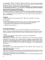
Front Panel Features
At the back of the manual, you'll find fold-out diagrams of the front and rear
panels. As you're reading the descriptions of the amp's features, you'll gain a better
understanding of the topic of discussion if you unfold and refer to them as we go!
1 Input
¼" unbalanced input jack. Plug your guitar in here using a shielded cord.
A tip from the designer:
Depending on the type of cord and its shielding, you may occasionally encounter
interference from sources such as radio stations or powerful magnetic fields. When
this occurs, try connecting your guitar to the amp using different cords. What's more,
to minimize signal degradation due to high-frequency loss, use the shortest cords
feasible (as a rule, the shorter the cord, the less susceptible it is to high-frequency
attenuation).
2 Gain Channel 1
The Channel 1 Gain control knob determines the preamp's input sensitivity and
amplitude when Channel 1 is active.
A tip from the designer:
Here's how this knob's settings relate to the type of guitar pickup. If you are using
single-coils, the preamp will start breaking up at about 6, and at around 4 or 5 with
more powerful humbuckers or an active pickup.
If you want a pristine clean sound, back off the Channel 1 Gain knob setting and switch
off Gain Boost (14).
6
If you want just a touch of preamp overdrive, I recommend the following settings for
single-coil pickups: Set the Gain knob between 7 and 10 and deactivate Gain Boost. For
humbuckers, set the knob between 5 and 8 to get moderate overdrive.
Then when you need a grittier tone perfect for playing rock riffs, all you have to do is
activate the Gain Boost in Channel 1.
This particular sound-shaping option (Channel 1 - Gain Boost activated) is comparable
to plugging an overdrive pedal into the amp's front end. This not only boosts the gain
level, it also re-voices the internal filter stages to boost the low mids and conjure a
more assertive tone.
CAUTION: Extremely high gain and volume levels can produce powerful feedback.
Avoid feedback squeals; they can lead to hearing loss and damage speakers! At higher
volumes, back off the Gain and Treble levels in order to prevent unchecked feedback!
3 Bright
This feature boosts the upper end of the high frequency range for Channel 1. Its
intensity decreases as gain settings increase.
A tip from the designer:
For a crisp or glassy tone, activate the Bright boost. It brightens the sound of
humbucking or muddy pickups. Use it to tweak the amp's tone to taste, activating it to
boost top-end frequencies or deactivating it to dampen high end response.
4 Bass
This is the preamp voicing section's passive low-frequency EQ for Channel 1.
5 Middle
This is the preamp voicing section's passive midrange frequency EQ for Channel 1.
6 Treble
This is the preamp voicing section's passive high-frequency EQ for Channel 1.
A tip from the designer:
The best way to get to know the amp and its fundamental sounds is to start out by
setting all tone knobs to the center position (: 5). These are passive tone controls
selected and tuned specifically for the whole retro concept, so their control ranges are
narrower than those of active EQs.
7 Volume Channel 1
Determines the level of Channel 1. Twist this knob to adjust Channel 1's volume and
dial in the desired balance of levels with Channel 2. Because this volume control is
located pre effects loop, it also determines the effects send level for Channel 1.
A Tip and Some Important Info from the Designer:
The inputs of modern effect devices can handle signal levels up to +10 dB, so it's a good
idea to dial up a higher send level for the FX loop. Do this by turning up the Channel 1
(7) and Channel 2 (13) preamp Volume knobs. Dial in settings higher than 5 to make
the most of the dynamic range between the preamp and power amp.
Once you have matched the preamp and effects device level, use the Master knob (16)
to adjust the amp's overall volume. If you insert older stomp-boxes devices into the
7
RetroTube amp's FX loop, you can reduce the level at the FX Loop Send jack (30) to
somewhere between -20 dB and -10 dB by setting the two channel Volume knobs
between 1 and 4. Older effects pedals usually don't handle high input levels well. Even
a -10 dB signal can cause undesirable distortion.
8 Gain Channel 2
Gain control for the Channel 2. This Control knob determines input sensitivity when
Channel 2 is active. Use it to dial in the desired amount of preamp saturation level.
A tip from the designer:
Preamp Channel 2 is a lot hotter than Channel 1 because its baseline gain level is a lot
higher. It is roughly comparable to that of Channel 1 with Gain Boost activated.
However, its tonal structure is different, giving you yet another flavor of overdriven
tone to spice up your musical act.
Activating Gain Boost sends Channel 2 into very different sonic territory with
sustaining lead tone that is great for soloing.
If you push Channel 2 hard while Gain Boost is active, the preamp gain will be
substantial and noise such as hissing and any buzzing produced by guitar pickups will
be amplified considerably. If you wish to configure the preamp so that both Channel 2
and Gain Boost are on, you can activate the Noise Gate (see section 29) to largely
suppress such noise.
CAUTION: Extremely high gain and volume levels in Lead mode can produce powerful
feedback. Avoid feedback squeals; they can lead to hearing loss and damage
speakers! At higher volumes, back off the Gain and Treble levels in order to prevent
unchecked feedback!
9 Tone
This sound-shaping button mainly influences the upper midrange. When activated, it
boosts the frequency range between 500 Hz and 1 KHz.
The LED above the button lights up to indicate Tone is activated.
The Tone sound feature may also be switched using a Z-9 Custom Footswitch
connected to the S.A.C. Port (21) or a footswitch connected to jack (23).
For more details see the chapter 21 and 23 on page 11 and 12 !
A Tip from the Designer:
The Tone button voices specific midrange frequencies that are instrumental in finetuning a guitar's sound. The amp's sound will be thicker when it is activated.
If you want a less dominant midrange, leave this feature deactivated; that is, don't
push this button. The Tone button also lets you adapt Channel 2's fundamental sound
to suit different types of guitar pickups.
10 Bass
This is the preamp voicing section's passive low-frequency EQ for Channel 2.
11 Middle
This is the preamp voicing section's passive midrange EQ for Channel 2.
12 Treble
This is the preamp voicing section's passive high-frequency EQ for Channel 2.
8
A tip from the designer:
To help you get acquainted with the amp's fundamental sounds, I recommend that
you set all tone controls to the center position; that is, to around 5. For higher-gain,
high-volume lead sounds, your best bet is to turn the Treble knob down to prevent the
pickups and speakers from generating undesirable feedback. I'd recommend a setting
below 5.
Though this passive voicing section's control range is narrower than that of a
comparable active system, its EQ curve is tweaked specifically for its designated
purpose and will give you satisfying results, so you have heaps of voicing options for
tailoring retro sounds to taste.
13 Volume Channel 2
Determines the level of Channel 2. Twist this knob to adjust Channel 2's volume and
dial in the desired balance of levels with Channel 1. Because this volume control is
located pre effects loop, it also determines the effects send level for Channel 2.
A tip and important info from the designer: see the chapter 7 on page 7!
14 Gain Boost
Press this button to increases the amplitude in Channel 1 and Channel 2 considerably.
The yellow LED above the button lights up to indicate Gain Boost is active. The button
(14) on the amp's front panel is disengaged when you switch Gain Boost via footswitch
(21, 24). Gain Boost may also be switched via an ENGL Z-9 Custom Footswitch
connected to the S.A.C. Port (21) or via a footswitch connected to jack 24. For more
details, see chapters 21 and 24 on page 11 and 12 !
A tip from the designer:
Activating Gain Boost in Channel 1 increases the gain level significantly, enough to push
the preamp into overdrive. This brings out and tightens up the middle frequencies to
conjure a more assertive sound for classic-style rhythm workouts. Activating Gain Boost
in Channel 2 kicks up the gain level considerably, saturating the preamp to give you far
more sustain and much thicker tone. This means you can coax blazing lead tone out of
the amp without having to connect an outboard gain enhancer or overdrive pedal. And
the sound quality may well send your stomp-boxes into retirement.
15 Channel 1 < > 2
This channel switching button selects Channel 1 or Channel 2. Press it to activate
Channel 2. The red LED above the button lights up to indicate Channel 2 is active.
Channels may also be switched via the ENGL Z-9 Custom Footswitch connected to the
S.A.C. Port (21) or via a footswitch connected to jack 24. For even greater convenience,
you could also use the optional ENGL Z-9 Custom Footswitch to select the two channels
in combination with the two Gain Boost stages directly by simply tapping the Z-9's four
channel-switching buttons. For more details, see chapters 21 and 24 on page11 and 12 !
16 Master A
Master A volume knob. Located post FX Loop, it adjusts the power amp's output level.
Master A is enabled and its setting determines the master level if you have not
connected a footswitch to the amp. If you have connected a footswitch you can use it
to activate another master level as determined by the Master B (27) knob setting.
9
A tip from the designer:
You could use an ENGL Z-9 foot controller, for example, to remotely control Master A,
the default when you are not using a footswitch, and Master B, which is only accessible
via footswitch. Then you could dial in different levels for Master A and Master B and
combine these with the amp's various modes – very practical for shaping tone and
controlling volume on the fly at gigs. Note that the four channel switches on the ENGL
Z-9 foot controller let you access Channel 1 and Channel 2, and each directly in
combination with Gain Boost and Master A/B modes. This gives you a range of
alternatives that you can apply to different playing styles and situations to great
dramatic effect, for instance, to play rhythm and more restrained leads over Channel 1
and then kick up the preamp gain for playing high-octane rock riffs and leads over
Channel 2.
Beyond that, you can also broaden the volume and tonal ranges by working your
guitars' volume knob. If your arsenal includes MIDI gear - for instance, the Z-11 ENGL
MIDI Switcher in combination with the Z-9 Custom Footswitch - you can use the Master
A/B switching function to call up different volume levels for the various preamp
setups.
17 Stand By
Power amp standby switch: Use this switch to silence (0 position) the amp when you
take longer break. The amp's tubes stay nice and toasty, and the amp is ready to roll
immediately when you ramp it back up to full power.
A tip from the designer:
I suggest you get into the habit of using standby during short breaks. In this mode,
current is not piped through the power tubes, so they don't get as hot (due to the lack
of anode dissipation) and are spared considerable wear. The amp is ready to run when
you flip the Standby switch because the tubes are already warm and don't require time
to heat up. For breaks of 30 minutes and longer, I recommend that you switch the amp
off in order to conserve energy.
18 Power
Mains power on/off.
Please note: ensure that the Stand By switch (17) is set to Stand By (0 position) before
you switch the amp on. Let the tubes heat up for about 30 seconds before you activate
the power amp. This procedure spares the tubes.
CAUTION: After an extended period of operation and higher ambient temperatures
the amps's chassis can become very hot, therefore avoid touching the rear panel
surface !
10
Rear Panel Features
At the back of the manual you'll find a folded page offering diagrams of the front and
rear panels. Please unfold and refer to it as you read through the descriptions of
features and functions!
19 Mains Connector (AC Power Inlet; IEC - C14 connector)
Plug the mains cord in here. For European models, use a standard non-heating
equipment connector cable.
CAUTION: Make sure you use an intact mains line cord with a grounded plug!
Before you power the amp up, ensure the voltage value printed alongside the mains
socket is the same as the current of the local power supply or wall outlet.
Please also heed the guidelines set forth in the separately included pamphlet,
Instructions for the Prevention of Fire, Electrical Shock and Injury.
20 Mains Fuse Box:
The rear chamber contains the mains fuse and in the front chamber, a spare fuse.
CAUTION: ALWAYS make sure replacement fuses are of the same type and have the
same ratings as the original fuse! Please refer to the fuse ratings table.
21 Footswitch: Serial Amp Control Port (S.A.C.)
This serial data input serves to control six of the amp's switching functions remotely. It
accepts the optional ENGL Z-9 Custom Footswitch as well as the optional ENGL Z11S.A.C. MIDI Switcher for use as a MIDI interface. Use a cord equipped with stereo 6.3
mm (¼") jack plugs to connect this input to the S.A.C. Out on the Z-9 Footswitch or Z11S.A.C. MIDI Switcher. The custom-designed Z-9 and the MIDI Switcher (in MIDI
interface mode) let you switch every amp feature designated as footswitchable in this
manual. You can configure the Z-9 Footswitch to control the two channels in
combination with Gain Boost and Master A/B and two further features directly.
To learn if a given feature may be controlled remotely, refer to its description herein.
You'll find a configuration table showing the Retro Tube Amp's functions on page 23.
The ENGL Z-9 Custom Footswitch is optional.
Heads up: Plugging a jack plug into the S.A.C. Port disables the Gain Boost and the
Channel switching functions controlled by the buttons (14, 15) arrayed on the amp's
front panel. What's more, it also disables the footswitch jacks' (24) remote-control
capability. In other words, when a Z-9 board is plugged in, it has priority over the amp's
Gain Boost and Channel switching controls as well as Gain Boost and Channel
switching via a footswitch connected to jack (24).
CAUTION: Connect only the ENGL Z-9 Footswitch or the ENGL Z11-S.A.C. MIDI
Switcher (S.A.C. Out) to this 6.3 mm (¼") stereo jack! Connecting any other
switching device may damage it and/or the amp's circuitry!
Insert and remove the Z-9's cable to and from the S.A.C. Port only when the amp is
switched off!
Please note: Never link two S.A.C. Ports of Engl amps via an Y-adaptor to a Z-9 Custom
Footswitch; this can cause ground hummming noise and damage the internal circuits!
A tip from the designer:
Try out the ENGL Z-9 Custom Footswitch - chances are you'll love the remote-control
convenience for your RetroTube amp. Based on a rather clever switching concept, it
11
features four switches that afford you direct access to Channel 1 and Channel 2 in
combination with the two Gain Boost stages.
Alongside selecting channels, you can opt to control any other two switchable amp
functions such as Tone and Master A/B or FX Loop and Noise Gate, and so forth.
Another tremendous benefit of this microcontroller-driven footboard is that it
connects to the amp via an easily obtained, standard stereo cord. But that's not the last
of the Z-9's advantages: At some point, you may decide to ramp up or connect to a
MIDI system using the ENGL Z11-S.A.C. MIDI Switcher. This won't render the Z-9
obsolete because it also serves as a simple MIDI footboard with a MIDI OUT (5-pin DIN
connector) that selects 10 MIDI patches (or presets, if you prefer). Again, I want to
emphasize that you should never connect another footboard to this jack: The Z-9 and
the Z11-S.A.C. control the amp via a proprietary ENGL serial data protocol, and the
Serial Amp Control Port was developed exclusively for ENGL amps. No other footboard
will work and in fact is likely to damage the footboard or the amp's circuitry!
You can use the ENGL Z11-S.A.C. MIDI Switcher to integrate the amp straight into a
MIDI system. You can also opt to control two amps in parallel using the Z11-S.A.C.
MIDI Switcher and MIDI commands. The Z11-S.A.C. Switcher is equipped with six
switching loops (accessed via three stereo jacks) and the S.A.C. Out (stereo jack) for
precisely this purpose!
22 Footswitch: FX Loop, Noise Gate Off - On
Use this ¼" (6.3 mm) stereo jack to connect a conventional footswitch with two
switching functions, for example, the ENGL Z-4 (2 x off/on - Single Pole Single Throw or
SPST for short). This type of footswitch lets you access FX Loop on/off and Noise Gate
on/off. One of the two switches enables or bypasses FX Loop, while the other switches
the Noise Gate on and off (Channel 2 with Gain Boost engaged only).
Note also: A footswitch may be equipped with LEDs indicating the given switching
status. Each of the two switches is provided with approx. 10 milliamperes current,
which suffices to power a standard LED. The jack's mono terminal controls FX Loop
on/off, while the stereo terminal controls Noise Gate on/off (for pin assignments, see
page 22).
23 Footswitch: Master A/B, Tone
Use this ¼" (6.3 mm) stereo jack to connect a conventional footswitch with two
switching functions, for example, the ENGL Z-4 (2 x off/on - Single Pole Single Throw or
SPST for short). This type of footswitch lets you access Master A/B and Tone. One of
the two switches activates Master A or B, while the other selects the Tone control,
which boosts Channel 2's midrange frequencies. Plugging a footswitch into this jack
disables onboard Tone (9) switching.
Note also: A footswitch may be equipped with LEDs indicating the given switching
status. Each of the two switches is provided with approx. 10 milliamperes current,
which suffices to power a standard LED. The jack's mono terminal selects Master A/B,
while the stereo terminal controls the Tone feature (for pin assignments, see page 22).
24 Footswitch: Channel 1 < > 2, Gain Boost
Use this ¼" (6.3 mm) stereo jack to connect a conventional footswitch with two
switching functions, for example, the ENGL Z-4 (2 x off/on - Single Pole Single Throw or
12
SPST for short). This type of footswitch lets you access the two channels and Gain Boost
off/on. One of the two switches activates Channel 1 or Channel 2; the other engages
Gain Boost. Plugging a footswitch into this jack disables onboard channel (15)
switching and Gain Boost (14).
Note also: A footswitch may be equipped with LEDs indicating the given switching
status. Each of the two switches is provided with approx. 10 milliamperes current,
which suffices to power a standard LED. The jack's mono terminal selects Channel 1 or
Channel 2, while the stereo terminal controls the Gain Boost feature (for pin
assignments, see page 22).
25 Power Tube V8 Fuse (Retro Tube 50 Amp - E762: Power Tube V6 Fuse )
A fuse in the rear chamber of this fuse drawer protects the V8 (Retro Tube 50: V6)
power tube. It is designed to blow in the event of an electrical problem with tube V8
(Retro Tube 50: V6). The Power Tube Fuse LED (28) lights up to indicate that one or
several of the four fuses has blown. There is a replacement fuse in the front chamber of
the fuse drawer.
CAUTION: Switching off the amp and pull the mains plug before opening the fuse
drawer!
Need-to-know info: Always make sure replacement fuses are of the same type and
have the same ratings as the original fuse! See section 28 for some more key facts
about tube defects.
26 Power Tube V7 Fuse (Retro Tube 100 Amp - E765)
A fuse in the rear chamber of this fuse drawer protects the V7 (Retro Tube 100) power
tube. It is designed to blow in the event of an electrical problem with tube V7 (Retro
Tube 100). The Power Tube Fuse LED (28) lights up to indicate that one or several of
the four fuses has blown. There is a replacement fuse in the front chamber of the fuse
drawer.
CAUTION: Switching off the amp and pull the mains plug before opening the fuse
drawer!
Need-to-know info: Always make sure replacement fuses are of the same type and
have the same ratings as the original fuse! See section 28 for some more key facts
about tube defects.
27 Master B
Master B volume knob. Located post FX Loop, it gives you an alternative to the Master
A knob (16). In another words, you can set a different power amp output level and
then activate this Master B volume via footswitch. If you wish to switch between
Master A and Master B, you have to connect an ENGL Z-9 Custom Foot Controller to
the S.A.C. Port (21) or footswitch such as the ENGL to jack no. 23. Two options for
controlling Master A/B via the Z-9 are described on page 10. You'll find tips on how to
make the most of Master A/B switching in section 16 on page 9 & 10.
28 Power Tube Fuse LED
This LED lights up to indicate one of the fuses in the fuse drawer (see the descriptions
under 25, 26, 33, 34) has blown to protect the power tubes.
13
Need-to-know info: As a rule, it is an electrical problem with the tube that causes a
power tube fuse to blow. Normally this power tube is defective and needs to be
swapped for a new tube. The best way to tell if the defect is permanent is to replace
the fuse before installing a new power tube.
The tube map on page xx shows the positions of the power tubes. The RetroTube 100
is equipped with four fuses for the V5, V6, V7 and V8 power tubes; the RetroTube 50
requires just two fuses for the two V5 and V6 power tubes. With a replacement fuse in
every fuse drawer, there are plenty of backups on board.
29 Noise Gate Threshold Level
This control activates an onboard Noise Gate serving to suppress any excess noise
generated when both Channel 2 and Gain Boost are active. To this end, twist the knob
clockwise, near or just beyond the 9 or 10 o'clock position.
In addition the Noise Gate can be controlled remotely (on/off) via a footswitch
connected to jack 22 (for details refer to chapter 22) or via the ENGL Custom
Footswitch Z-9 (refer to chapter 21 for details). If you want to control the Noise Gate
remotely via footswitch, you must set the Threshold knob to 10 o'clock or beyond.
Use this knob to set a threshold value (that is, the noise level) at which the Noise Gate
activates to suppress the signal within the 9 to 5 o'clock range. The further you twist
the knob to the right, the higher the signal level at which the Noise Gate kicks in. If you
set the knob to the 5 o'clock position, the Noise Gate reacts to extremely high noise
levels, meaning that there's not much of a margin between the guitar signal and
background noise.
A tip from the designer:
Noise is a definite no-no in many situations. For example, studio etiquette demands
that you keep a lid on extraneous noise during short breaks. It's in the nature of highgain rigs to generate undesirable peripheral noise in overdriven (high gain) channels.
This is attributable to the physical properties of an amp's constituent components, in
particular its active components. That's right; those cherished tubes are the culprits.
The Noise Gate is a tool that lets you silence this noise during breaks by way of signal
mute circuit. Note that electric guitars pick up interference signals, and these are
amplified tremendously at high gain levels (Channel 2 with Gain boosted). The most
common source of noise is 50 Hz or 60 Hz (hertz/cycle) mains hum, particularly when
the guitar is positioned near transformers and power units. Because in worst-case
scenarios this humming can attain extremely high levels, the Noise Gate can hardly
distinguish between the musical signal and noise. This makes it hard to find the right
Threshold setting. It is entirely possible for this humming and other noise to rise to a
level that deactivates the Noise Gate and therefore becomes audible. My advice is to
stay as far away from transformers and power units as space allows.
IMPORTANT note; please read and heed: The Noise Gate may open up inadvertently
when the Noise Gate is activated, a high-gain Lead channel is selected, and the volume
exceeds the Threshold knob setting. At very high volume and gain settings, this may
generate instant feedback, particularly if your guitar is facing the speakers. Rather
than musical and controlled, this is the shrill, unpleasant and potentially harmful
variety of feedback squealing that sends your audience and fellow musicians packing.
Though the amp is not more susceptible to feedback when the Noise Gate is activated,
14
the fact that it suppresses extraneous noise means you can't hear those telltale signs
that feedback is swelling and consequently can't take measures to suppress it. For this
reason, make an extra effort to be careful when the Noise Gate is activated: Before
you approach the amp and speaker cabinet with your guitar in hand, turn the guitar's
volume knob to the far left position (to 0 so that no signal is audible) to prevent the
pickups and speakers from interacting!
30 FX Loop Send
Connect the FX Loop output to a signal processor's input/return jack using the shortest
possible shielded cord equipped with 1/4" plugs. The FX Loop can be controlled
remotely (: on/off) via a footswitch connected to jack 22 (for details refer to chapter
22) or via the ENGL Custom Footswitch Z-9 (refer to chapter 21 for details). In the
signal path, the FX Loop is located post preamp and pre the two power amp Master
knobs.
NOTE: The FX Loop Send output is removed from the preamp signal path when the FX
Loop is deactivated.
31 FX Loop Return
Connect the FX Loop input to a signal processor's output/send jack using the shortest
possible shielded cord equipped with 1/4" plugs. The FX Loop can be controlled
remotely (: on/off) via a footswitch connected to jack 22 (for details refer to chapter
22) or via the ENGL Custom Footswitch Z-9 (refer to chapter 21 for details). In the
signal path, FX Loop is located post preamp and pre the two power amp Master
knobs.
NOTE: The effect signal at the FX Loop Return input is removed from the signal path
when the FX Loop is deactivated.
32 FX Loop Balance
FX mix control for the FX Loop. When the knob is set to Dry, the amp signal is routed
through with no processed signal (0% wet balance) added to the mix. Twist the knob
clockwise to blend in the processed signal (parallel/passive, wet balance 1-99%,
depending on knob position). When the knob arrives at the Effect position, only the
wet signal (that is, the processed signal generated by the connected effect device) is
patched to the power amp (serial, 100% wet).
NOTE: Set this knob to Dry when this loop is not in use! Settings between the 9 and 3
o'clock position reduce the signal level.
33 Power Tube V5 Fuse
A fuse in the rear chamber of this fuse drawer protects the V5 power tube. It is
designed to blow in the event of an electrical problem with tube V5. The Power Tube
Fuse LED (28) lights up to indicate that one or several of the four fuses has blown.
There is a replacement fuse in the front chamber of the fuse drawer.
CAUTION: Switching off the amp and pull the mains plug before opening the fuse
drawer!
Need-to-know info: Always make sure replacement fuses are of the same type and
have the same ratings as the original fuse! See section 28 for some more key facts
about tube defects.
15
34 Power Tube V6 Fuse (Retro Tube 100 Amp - E765)
A fuse in the rear chamber of this fuse drawer protects the V6 (Retro Tube 100) power
tube. It is designed to blow in the event of an electrical problem with tube V6 (Retro
Tube 100). The Power Tube Fuse LED (28) lights up to indicate that one or several of
the four fuses has blown. There is a replacement fuse in the front chamber of the fuse
drawer.
CAUTION: Switching off the amp and pull the mains plug before opening the fuse
drawer!
Need-to-know info: Always make sure replacement fuses are of the same type and
have the same ratings as the original fuse! See section 28 for some more key facts
about tube defects.
35, 36 Poweramp Output, 4 Ohms Parallel
4 ohms speaker output jacks, internal connected parallel. For diverse cabinet options
see the chapter Cabinet options !
37, 38 Poweramp Output, 8 Ohms Parallel
8 ohms speaker output jacks, internal connected parallel. For diverse cabinet options
see the chapter Cabinet options !
39 Poweramp Output, 16 Ohms
16 ohms speaker output jack. For diverse cabinet options see the chapter Cabinet
options !
IMPORTANT NOTE, please read and heed: Never operate the power amp without a
sufficient load, otherwise you may damage or destroy it! Always check the connected
cabinets' impedance to confirm it matches the amp's output impedance! For example,
if you are connecting a cabinet to one of the two 8-ohms output, make sure the
speaker system is indeed rated for 8 ohms. You'll find the various speaker and cabinet
options listed in the nest section. I cannot stress enough the importance of proper
impedance matching when connecting one or more cabinets to your amp. Impedance
mismatching can damage the power amp!
Cabinet options
1. One 4-ohm cabinet connected to a 4-ohm jack;
Summary: 4 Z, -> connected to 4-ohm output.
2. Two 8-ohm cabinets connected to the 4-ohm jacks;
Summary: 8 Z + 8 Z, -> connected to 4-ohm + 4-ohm output.
3. One 8-ohm cabinet connected to an 8-ohm jack;
Summary: 8 Z, -> connected to 8-ohm output.
4. Two 16-ohm cabinets connected to the 8-ohm jacks;
Summary: 16 Z + 16 Z -> connected to 8-ohm + 8-ohm output.
5. One 16-ohm cabinet connected to the 16-ohm jack;
Summary: 16 Z -> connected to 16-ohm output.
6. An 8-ohm cabinet connected to one of the 4-ohm jacks in combination
with a 16-ohm cabinet connected to one of the 8-ohm jacks
Summary: 8 Z + 16 Z -> connected to 4-ohm + 8-ohm output.
16
Handling and Care:
* Keep the amp safe from hard knocks and shocks. Tubes are fragile and tend
to suffer when exposed to mechanical stress!
* Let the amp cool down before you transport it. Ten minutes or so will spare
the tubes.
* Tubes take some 20 seconds to warm up after you switch the power on, and
about two to three minutes before they are able to pump out full power. Make
a habit of giving your amp plenty of time to get toasty and flipping the Standby
switch for short breaks.
* In order to spare the power tubes and prolong their lifetime, we recommend
to set the Stand By switch to Stand By (0 position, that is) before you switch
the amp on. After a period of 30 seconds you may activate the poweramp by
flipping the Stand By switch.
* Avoid storing the amp in damp or dusty rooms to spare jacks, switches and
potentiometers. If you don't use the amp all the time, I recommend that you
drape a covering over it to prevent the intrusion of dust. Even better, keep it
in a transport cover or flight case.
* Never use caustic or scouring detergents to clean the amp's housing, front or
rear panels. Use a soft, damp cloth or sponge with diluted soapsuds or a
standard brand of mild dishwashing liquid instead. Never use solvents they can
corrode the amp's vinyl skin and dissolve the front and rear panel labels. Keep
liquids well away from the amp, particularly the interior of the housing.
* Make sure air can circulate at the rear and top of the amp to allow for
adequate cooling, which increases component life.
* Never operate the amp without an adequate load (a speaker, cabinet or
suitable terminating resistor).
* High ambient temperatures place an additional strain on diverse components; so
if at all possible, avoid operating the amp at temperatures far higher than 30°C
for longer periods. Running the amp at mains voltages exceeding the nominal
mains input voltage over longer periods can also shorten component life.
* Replace tubes with selected tubes that satisfy ENGL selection criteria to forestall
microphonic properties, undesirable noise and unbalanced power amp signals.
Because power tubes' idle current (bias) must checked and possibly adjusted
when replacing tubes, this is a job best left to experienced and authorized
specialists.
17
Troubleshooting
* Some features that may be controlled remotely using a Z-9 or Z-4 footswitch
fail to respond when you change settings:
-> Powerful static charges, strong radio signals, or mains voltage spikes can affect
microcontroller-driven systems, setting them to an undefined status commonly
called a hung chip. In this event, your only choice is to reset the system. Simply
switch the amp off and on again.
-> If a reset doesn't solve the problem, there is a defect in the control system,
probably on the logic board holding the microcontroller or merely a faulty
contact on one of the four stereo footswitch jacks (21, 22, 23, 24). In this case,
consult an authorized service center or a professional specialist.
* The amp fails to respond when you try to control switching functions remotely
via the Z-9 footboard.
-> Is the Z-9 footboard connected to the S.A.C. Port (21)?
-> Is the cord you are using stereo, intact, and wired properly?
(Refer to page 22 for pin assignments.)
* The amp fails to respond when you try to control switching functions remotely
using a footboard such as the Z-4 or a MIDI switcher such as the ENGL Z-11.
-> Are the footboards or switching loops connected to the corresponding
footswitch jacks (22, 23, 24)?
-> Are the cords you are using stereo, intact, and wired properly?
(Refer to page 22 for pin assignments.)
-> If you are using footswitches other than an ENGL Z-4 or Z-11, are the switches
or relays inside the boards or switching loop systems off / on Single Pole Single
Throw (SPST) switches? In other words, do these switches continuously connect
to GND when you wish to activate the given function? If you're unsure about
the answers to these questions, consult an authorized service center or a
professional specialist.
* The amp is not providing an output signal / no sound is emanating
from the speaker.
-> Is at least one speaker connected to the speaker outputs 4 ohms, 8 ohms
or 16 ohms (35, 36, 37, 38, 39) ?
-> Is the power amp activated (Standby switch to ON) ?
-> Are all cords (guitar, effect, and speaker) connected properly
and are they functional ?
-> Unplug connected effectors and see if the preamp works fine without
these peripheral devices.
-> Is the Noise Gate activated in one of the Lead channels and the Threshold (29)
knob set to a high value? Deactivate the Noise Gate (29) for a quick check.
-> Are the active Master knob and the Gain and Volume knobs set to a value
greater than 0 ? If any of these knobs is set to 0, no signal is routed to
the amp's outputs.
18
-> You may be looking at a faulty tube or another defect. In this case,
be sure to take the preamp to an authorized, professional service center.
* The speaker is emitting humming noises:
-> Is there a connection (for example, via a shielded circuit) between the
amp and another device that is grounded via a power plug of its own?
Two or more circuits sharing a common electrical ground line can cause
audible hum. If low-frequency noise is emanating from your rig,
be sure to consult a specialist.
-> The amp and mains grounds are not connected properly or are altogether
disconnected. Have an experienced specialist check this.
-> Cords connected to the input or effect loops may not be shielded properly.
Replace them to check if this is indeed the case.
-> The amp or speaker cords may be picking up interference from powerful
magnetic fields (for example, of nearby power transformers or electrical motors).
Reposition the amp and connector cables.
-> The amp or speaker cords may be picking up radio signals, for example,
from activated mobile telephones or powerful local transmitting stations nearby.
Switch off mobile phones while troubleshooting noise problems.
* One of the power tube fuses blows:
-> The given power tube is probably defective. If that power tube's fuse is replaced
and the new fuse also blows, the tube needs to be swapped out.
-> The amp has been overloaded, perhaps by excessive volume levels, excess mains
voltage, or the wrong output impedance (where the impedance setting does not
match the connected speaker's impedance).
Check the speakers' overall impedance and, if necessary, adjust your setup
accordingly (see the list on page 16). Refer to section 28 for some more key facts
about tube defects.
19
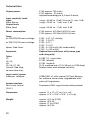
Technical Data
Output power:
Input sensitivity levels
Input:
Effect Return:
Output levels
Effect Send:
Power consumption:
Fuses:
at 220/230/240 mains voltage
at 100/115/120 mains voltage
Power Tube Fuses:
Important:
Tubes
V1:
V2, V3:
V4:
V5, V6, V7, V8:
Consult Tube Map
to view tube array
Logic control system
Processor, software:
E765: approx. 100 watts;
E762: approx. 50 watts;
adjusted accordingly to 4, 8 and 16 ohms;
range: --40 dB to -10 dB (Channel 1), max. 0 dB
range: -20 dB to 0 dB, max. 5 dB
range: -20 dB to
0 dB, max. 5 dB
E765: approx. 410 Watt (490 VA) max.
E762: approx. 220 Watt (260 VA) max.
E765: 2 AT L (T: slo-blo);
E762: 1,25 AT L
E765: 4 AT L
E762: 2,5 AT L
E765: 4 x 160 mAM (M: medium-blo);
E762: 2 x 160 mAM
Replace these with fuses of the same type
and rating only!
ECC83 F.Q., input tube;
ECC83 selected;
ECC83 standard;
EL34, matched sets; (V7 & V8 only in E765 Amp)
Replace tubes with selected sets only!
AT89C2051 µC with internal 2K Flash Memory
for software source code; Upgradeable with
external Programmer;
System interface:
Serial Amp Control
(S.A.C.)
Proprietary ENGL asynchronous data protocol.
Dimensions:
approx. 71 x 27 x 27 cm (l x h x d);
approx. 27.9" x 10.6" x 10.6" (l x h x d);
Weight:
approx. 22,5 kg (E765)
approx. 49,4 lbs
approx. 21 kg (E762)
approx. 46,3 lbs
20
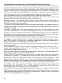
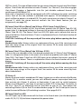
Tube Map:
E762:
V5
V6
Mains
Transformer
Output
Transformer
E765:
V5
V6
V7
V1
V2
V3
V4
Input
V8
amp chassis
as viewed
from above;
Front panel
the tubes and their function:
V1 - ECC83 (12AX7): input stage, 2. gain stage; grade: FQ selected
V2 - ECC83 (12AX7): Channel 2 driver stage, 4. stage; grade: selected
V3 - ECC83 (12AX7): FX buffer stage, poweramp driver stage; grade: selected
V4 - ECC83(12AX7): phase splitter; grade: standard
E762: V5, V6: EL34: power tubes, poweramp, matches set
E765: V5 to V8: EL34: power tubes, poweramp, matches sets
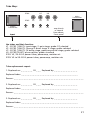
Tube replacement report:
1. Replaced on: _ _ _ _ _ _ _ 20 _ _ _ Replaced by: _ _ _ _ _ _ _ _ _ _ _ _ _ _
Replaced tubes: _ _ _ _ _ _ _ _ _ _ _ _ _ _ _ _ _ _ _ _ _ _ _ _ _ _ _ _ _ _ _ _ _ _
Reason: _ _ _ _ _ _ _ _ _ _ _ _ _ _ _ _ _ _ _ _ _ _ _ _ _ _ _ _ _ _ _ _ _ _ _ _ _ _ _ _ _ _
2. Replaced on: _ _ _ _ _ _ _ 20 _ _ _ Replaced by: _ _ _ _ _ _ _ _ _ _ _ _ _ _
Replaced tubes: _ _ _ _ _ _ _ _ _ _ _ _ _ _ _ _ _ _ _ _ _ _ _ _ _ _ _ _ _ _ _ _ _ _
Reason: _ _ _ _ _ _ _ _ _ _ _ _ _ _ _ _ _ _ _ _ _ _ _ _ _ _ _ _ _ _ _ _ _ _ _ _ _ _ _ _ _ _
3. Replaced on: _ _ _ _ _ _ _ 20 _ _ _ Replaced by: _ _ _ _ _ _ _ _ _ _ _ _ _ _
Replaced tubes: _ _ _ _ _ _ _ _ _ _ _ _ _ _ _ _ _ _ _ _ _ _ _ _ _ _ _ _ _ _ _ _ _ _
Reason: _ _ _ _ _ _ _ _ _ _ _ _ _ _ _ _ _ _ _ _ _ _ _ _ _ _ _ _ _ _ _ _ _ _ _ _ _ _ _ _ _ _
21
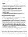
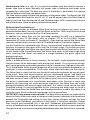
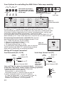
Your Options for controlling the ENGL Retro Tube amp remotely:
(21)
(22)
S.A.C. PORT
(23)
SERIAL AMP
FX LOOP
CONTROL PORT NOISE GATE
CAUTION:
OFF-ON
CONNECT
CUSTOM
FOOTSWITCH Z-9 ONLY!
#1
(24)
MIDI SWITCHER / TYPE: Z11-S.A.C.
FOOTSWITCH
MASTER
A/B
TONE
#2
#2
POWER
SUPPLY
CHANNEL
1
2
GAIN BOOST
Footswitch connectors
(4 x stereo jack sockets)
located at the rear panel
of the amp.
x
MIDI THRU
MIDI IN
LOOP 1 & 2
ENGL MIDI
COM. L2 L1
FOOTCONTROLLER
LOOP 3 & 4
COM. L4 L3
LOOP 5 & 6
COM. L6 L5
Z9, Z12, Z15
The ENGL Z11-S.A.C.
MIDI Switcher's rear panel
#1
S.A.C. Out
#1
#2
MIDI
Out
R
SERIAL AMP
CONTROL OUT
(S.A.C.)
12 Volts AC
12 Volts DC
300 mA
Serial Amp Power Supply In
7-14 Volts AC
Control Out
9-20 Volts DC
Caution !
approx. 100 mA
Connect To
Amplifier
Only!
Design by
Horst Langer
Tube
Ser.Cnt.:
Channel 1
MIDI:
Patch 1/6
Amp
Technology
Ser.Cnt.:
Channel 2
Ser.Cnt.:
Channel 3
Ser.Cnt.:
Channel 4
Ser.Cnt.:
Function 1
Custom
Footswitch
Z-9
MIDI:
Patch 2/7
MIDI:
Patch 3/8
MIDI:
Patch 4/9
MIDI:
Patch 5/10
To assign Amp switching
features to the Function
1 and 2 button, press the
Channel 1 and the
respective Function button
simultaneously until the
LED starts flashing.
Now use the buttons
1 to 4 to select
the desired switching
feature (press 1x or 2x).
Store the selected
switching feature by
pressing the opposite
Function button
for approx. 1 second.
Ser.Cnt.:
Function 2
MIDI:
Bank A/B
ENGL Z-9
Custom Footswitch
#1 ENGL Z-9 Custom Footswitch: This specialized footboard connects to the amp
via a 6.3 mm (¼ ”) stereo cord plugged into the Serial Amp Port - S.A.C. (21).
The Z-9 affords you direct access to the amp's two Channels in combination with
Gain Boost simply by tapping the four channel switching buttons, and lets you
control two special functions, for example, Tone and FX Loop.
As an alternative to the Z-9 footswitch, you can also connect the ENGL Z11-S.A.C.
MIDI Switcher (S.A.C. Out) to the amp's S.A.C. Port for use as a MIDI interface. #2
#2 A two-way footswitch such as the ENGL Z-4: Connect
dual footswitches to the amp by plugging stereo 6.3 mm
(¼ ”) cords into jack nos. 24, 23, and 22.
-> Channel 1< >2 and Gain Boost (1 x Z-4);
-> Master A/B and Tone (1 x Z-4);
ENGL Z-4
dual footswitch
-> FX Loop and Noise Gate (1 x Z-4);
As an alternative to dual footswitches, you can connect
a MIDI switcher (the ENGL Z-11 will do nicely) to these
three jacks to control the six switching functions.
R
Tube
Amp
FOOTPEDAL
Z-4
ON/OFF
ON/OFF
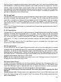
Wiring of Principal Connectors
Dual Footswitch (22, 23, 24)
Serial Amp Control Port (21)
Stereo
1/4" jack
Stereo
1/4" jack
Use a stereo
plug only!
page: 12
ring: refer to *R
tip: refer to *T
sleeve: Ground, GND
Very important:
use a stereo
plug only!
Connect ENGL
Custom Z-9
Footswitch only!
Here you'll find at a glance the technical details
of the Retro Tube Amp's various remote switching capabilities:
A switch connected to this terminal *R controls
Noise Gate; off <-> on via jack 22;
Tone; passive <-> active via jack 23;
Gain Boost; passive <-> active via jack via jack 24.
A switch connected to this terminal *T controls
FX Loop; off (bypassed) <-> on (enabled) via jack 22;
Master A/B; Master A <-> Master B via jack 23;
Channel 1< >2; Channel 1 <-> 2 via jack 24.
22
page: 11
ring: Data
tip: + 5 volts
sleeve: Ground, GND
tip
ring
sleeve
Stereo
1/4" plug
Configuration table for assigning the Retro Tube Amp's sound-shaping
and special functions to the Z-9 Custom Footswitch's Functions 1 and 2 :
Button
Function 1
Function 1
Function 1
Function 1
Function 1
Function 1
Function 1
Function 1
Function 2
Function 2
Function 2
Function 2
Function 2
Function 2
Function 2
Function 2
amps's Functions
Master A/B
no
FX Loop off / on
Noise Gate off / on
no
Tone
no
no
no
no
no
Noise Gate off / on
no
Tone
FX Loop off / on
no
Setup
1: Channel 1
1: Channel 2
1: Channel 3
1: Channel 4
1: Channel 1
1: Channel 2
1: Channel 3
1: Channel 4
2: Channel 1
2: Channel 2
2: Channel 3
2: Channel 4
2: Channel 1
2: Channel 2
2: Channel 3
2: Channel 4
Indication
LED 1 lights
LED 2 lights
LED 3 lights
LED 4 lights
LED 1 flashes
LED 2 flashes
LED 3 flashes
LED 4 flashes
LED 1 lights
LED 2 lights
LED 3 lights
LED 4 lights
LED 1 flashes
LED 2 flashes
LED 3 flashes
LED 4 flashes
S.A.C.
F1-1
F1-2
F1-3
F1-4
F1-5
F1-6
F1-7
F1-8
F2-1
F2-2
F2-3
F2-4
F2-5
F2-6
F2-7
F2-8
Comments:
Column 1 lists the Function button on the Z-9. Column 2 lists the sound-shaping
and special functions that can be assigned to it.
Column 2 lists sound-shaping and special functions on the ENGL Retro Tube Amp
that can be controlled remotely via the Z-9 Custom Footswitch.
Column 3 lists the configuration or setting required to remote-control
sound-shaping or special functions on the Retro Tube Amp.
The first digit indicates the Function Setup routine, that is,
1: for Function 1 Setup and 2: for Function 2 Setup.
Channel 1 to Channel 4 denotes the button used to enter the setting.
Column 4 indicates the currently or newly selected configuration. For example, if
LED 3 flashes when the Z-9's Function 2 Setup routine is activated,
then the Retro Tube Amp's FX Loop switching feature is currently assigned to
Function 2; the corresponding S.A.C. command is F2-7.
Column 5 lists the shorthand designations for specific configurations that appear
throughout the Z-9 Operator's Manual. For detailed information,
please refer to the Z-9 Custom Footswitch Operator's Manual.
Please note: The ENGL Z-9 Custom Footswitch is an optional accessory. The
afore mentioned Function buttons, LEDs and setup routines pertain to the Z-9.
23
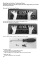
Mounting Instructions: front panel frame
CAUTION: Switch the amp off and pull the mains plug before you remove
the front panel frame!
Remove the front panel frame:
pull the front panel frame (without the grille!) until
the locking mechanism unlatches;
raise it slightly then remove it from front of the Amp.
A: Phillips screws
8 pcs included, 2 pcs required per clasp;
B: clasp for locking mechanism (latch)
4 pcs included, 2 pcs required for each front panel frame
C: required tool:
Phillips screwdriver (not included);
24
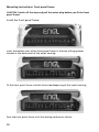
Mounting Instructions: front panel frame
Fix the clasps on the front panel frame:
boreholes for the clasps;
place the first clasp;
attach this clasp with two screws;
tighten the screws carefully;
assemble the second clasp in the same way on the opposite side of the hole.
25
Mounting Instructions: front panel frame
CAUTION: Switch off the amp and pull the mains plug before you fit the front
panel frame!
Install the front panel frame:
insert the bottom part of the front panel frame in the two milling grooves
located at the base panel of the amp's housing;
Fit the front panel frame into the front side deepening of the amp's housing;
Push the front panel frame until the locking mechanism latches.
26
Space for User Notes:
27
R
Tube
Amp
Technology
Gerätebau GmbH
Germany
Internet: http://www.engl-amps.com
Text, design, graphics, Amp photo and layout by
Horst Langer,
Amp Designer
0
10
9
!
20
0
4
10
9
1
0
5
5
10
6
9
1
0
4
6
5
10
6
9
1
0
4
7
5
21
23
24
CHANNEL
1
2
GAIN BOOST
<------- 12 ------->
22
MASTER
A/B
TONE
3
9
3
1
2
0
10
10
3
9
1
82
7
0
4
11
5
10
6
9
1
0
4
12
5
MAX.
26 27
LEVEL
MIN.
28
POWER
TUBE
FAILURE
CHECK
FUSE
V5 TO V8 !
<-----------------13 ---------------->
25
POWER TUBE V7
FUSE
POWER TUBE V8
FUSE
MASTER
B
MAX.
>14<
29
THRESHOLD
MIN.
NOISE
GATE
31
RETURN
EFFECT
9
1
0
5
10
6
9
8
7
14 15
GAIN CHANNEL
BOOST 1
2
1
2
3
0
4
POWER TUBE V6
FUSE
POWER TUBE V5
FUSE
6
10
8
7
Amp
Tube
9
8
OR 16
AND 16
OR ->
35
36
37
38
1 x 8 OHMS
2 x 16 OHMS
Or ->
8 OHMS PARALLEL
AND 8
1 x 4 OHMS
2 x 8 OHMS
OR 8
POWERAMP OUTPUT
4 OHMS PARALLEL
4
18
POWER
<---- 10 ---->
17
STAND BY
16
39
16 OHMS
<------------------------------------ 16 ------------------------------------>
34
MADE IN GERMANY
All-tube Guitar Amp Head
RetroTube 100 - E765
designed by Horst Langer
optically refined by Edmund Engl
R
16
5
MASTER
<------------ 9 ------------>
13
32 33
BALANCE
DRY
3
82
7
4
VOLUME
<------------ 15 ------------>
30
SEND
FX LOOP
10
6
TREBLE
3
82
7
MIDDLE
<------------------------- 8 ------------------------->
8
10
TONE
6
CAUTION !
0
9
8
7
5
BASS
4
DO NOT OPEN FUSEHOLDER
WHILE AMP IS SWITCHED ON !
REPLACE FUSES ONLY AGAINST
SAME TYPE AND RATING !
1
2
6
CAUTION !
9
8
7
5
GAIN
4
CHANNEL 2
DO NOT OPEN FUSEHOLDER
WHILE AMP IS SWITCHED ON !
REPLACE FUSES ONLY AGAINST
SAME TYPE AND RATING !
10
6
VOLUME
3
82
7
TREBLE
3
82
7
FOOTSWITCH
SERIAL AMP
FX LOOP
CONTROL PORT NOISE GATE
CAUTION:
OFF-ON
CONNECT
CUSTOM
FOOTSWITCH Z-9 ONLY!
S.A.C. PORT
page:
<--------------------11 -------------------->
19
1
3
82
7
4
MIDDLE
<---------------------------- 7 ---------------------------->
3
CAUTION !
<----- 6 ----->
1
2
8
7 BRIGHT 3
3
2
2
5
6
BASS
4
5
6
GAIN
4
DO NOT OPEN !
RISK OF ELECTRIC SHOCK !
DO NOT EXPOSE THIS EQUIPMENT
REPLACE FUSE
TO RAIN OR MOISTURE !
ONLY WITH SAME TYPE
AND RATING !
page:
1
INPUT
CHANNEL 1