1
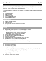
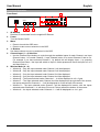
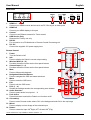
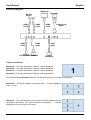
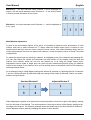
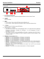
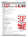
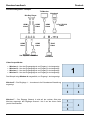
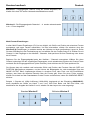
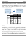
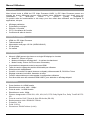
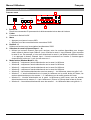
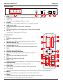
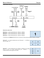
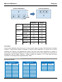
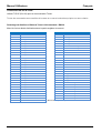
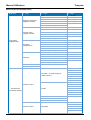
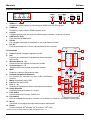
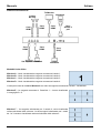
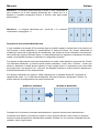
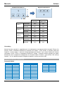
HDMI 4x1 PiP Video Processor User Manual Benutzerhandbuch Manuel Utilisateur Manuale Eng lis h Deutsch Français Italiano No. 38130 www.lindy.com Tested to Comply with FCC Standards For Home and Office Use! © LINDY ELECTRONICS LIMITED & LINDY-ELEKTRONIK GMBH - SECOND EDITION (September 2014) User Manual English Introduction Thank you for purchasing the LINDY HDMI 4x1 PiP Video Processor. The PiP Video Processor allows the signals from four different sources to be integrated for display on a single monitor, for viewing in Multi-View, Picture in Picture, Overlay (Chromakey) layouts. This flexible feature rich product has been designed to be used in a number of different applications, such as: Public Advertisement Digital Presentation Broadcasting & Control CCTV, Surveillance & Control Conference & Meeting Room Package Contents HDMI 4x1 PiP Video Processor IR Remote Control Multi-Country 12V 3A Power Supply (UK/EU/US/AUS) Driver CD This manual Features Allows 4 HDMI Inputs to be shown on a single HD displays in 4 modes PiP Mode: Picture in Picture Multi-Window Mode: View 2 – 4 Inputs simultaneously Overlay Mode: Picture On Picture with Chromakey Seamless switching between HDMI sources User definable channel size and position adjustment Independent audio selection Controlled via On-panel controls, IR Remote, RS-232 and Telnet Adjustable picture contrast, brightness, saturation and hue Memory function to store 4 user determined configurations Can be used with LINDY HDMI extenders to reach a remote display Specification Input ports: 4 x HDMI Female Input resolution: 480i – 1080p Output ports: 1 x HDMI Female Output resolution: 1080p Audio support: LPCM 2CH, 6CH, 8CH, AC3, DTS, Dolby Digital Plus, Dolby TrueHD & DTS-HD Control Ports: RJ45 (Telnet) & Serial 9 Way Male (RS-232) Video bandwidth: 225MHz/6.75Gbps Power consumption: 15W Weight: 2.95 kg Dimensions: 436x247x44mm (WxDxH) User Manual English Overview & Operation 6 Front Panel POWER MENU 1 1. 2. 3. 4. 5. 6. 2 3 - WINDOW A/1 B/2 C/3 D/4 E/ F/ CHANNEL INPUT 1 2 3 4 G/ H/ + 4 5 IR Window Receives IR commands from the supplied IR Remote Power Turn the Switch On/Off Menu Press to launch the OSD menu Press to make a menu selection in the OSD -/+ Buttons Use these buttons to move up and down in the OSD Channel Input (1 – 4) Selection Use the Channel Input buttons to cycle through the available Inputs for each Channel; use Input Channel button 1 to control Channel 1, Input Channel button 2 to control Channel 2 and so on. For example if you have selected Channel 1, by default this will display Input 1, by pressing Channel Input button 1 the Input will switch to Input 2, further presses will move the Input to 3 to 4 and then back to 1. Window Mode (A – H) Window A – Only the Input selected under Channel 1 will be displayed. Window B – Only the Input selected under Channel 2 will be displayed. Window C – Only the Input selected under Channel 3 will be displayed. Window D – Only the Input selected under Channel 4 will be displayed. Window E – The Inputs selected under Channels 1 – 4 will be displayed in a 2 x 2 grid. Window F – The Input selected under Channel 4 will be displayed on the right half of the screen, the Inputs selected for Channels 1 – 3 will be displayed in on the left half of the screen. Window G – The Input selected under Channel 1 will be displayed full screen, with the Inputs selected under Channels 2 – 4 will show (Picture in Picture) across the bottom of the screen. Window H – the Inputs selected under Channels 1 – 4 will be displayed in a 4 x 1 grid. User Manual English Rear Panel HDMI IN 1 1. 2. 3. 4. 5. 6. 2 3 4 2. 3. 4. 5. 6. 7. 8. 9. 10. 11. 12. 13. 14. CONTROL USB SERVICE ONLY 2 1 4 3 HDMI In 1 – 4 Connect your HDMI sources devices such as PC, Blu-ray etc to these ports HDMI Out Connect your HDMI display to this port Control Connect to an Ethernet network for Telnet control USB Service Only Reserved for Factory use only RS-232 For connection to a PC/Notebook or Remote Control Processing unit DC 12V Connect the supplied 12V power supply here Remote Control 1. HDMI OUT RS232 DC 12V 5 6 INFO 2 Power WA WE Turn the Switch on/off WB WF Info Press to display the Switch’s current output setting 3 WC WG Window Mode (A – H) Provides the same function as the front panel buttons WH WD Channel Input (1 – 4) Mute Provides the same function as the front panel buttons 5 Mute Press to Mute audio playback OK Navigation/Selection Buttons Exit Press to navigate the OSD and make selections 8 Menu Fade In/Out Audio 1 Press to enter the OSD menu 10 Exit 11 Audio 2 Chromakey Press to exit the OSD menu FAV. (1 – 4) Mirror Audio 3 Recalls the settings saved to the corresponding save location 13 Rotation Audio 4 Audio Selection Press to select audio from Inputs 1 – 4 Fade In/Out Press this button to switch the Fade-in-out function on/off Chromakey* Press to enter Chroma mode, where CH1 is the background and CH2 is the top image Mirror* Press to display a mirror image of the selected input Rotate* Press to rotate the input: 900 Right, 900 Left and 1800 (Flip) *These features are only available in Window modes A – D POWER 1 CH 1 CH 2 4 CH 3 CH 4 Input 6 Menu 7 FAV.1 9 FAV.2 FAV.3 12 FAV.4 14 User Manual English Connection Diagram TV/Monitor Notebook Blu-Ray Player HDMI Cable HDMI Cable HDMI Cable HDMI Cable Set-Top Box Notebook 9 Way Serial Cable HDMI Cable RJ45 Cable Notebook Video Output Modes Window A – The Input selected for Channel 1 will be displayed. Window B – The Input selected for Channel 2 will be displayed. Window C – The Input selected for Channel 3 will be displayed. Window D – The Input selected for Channel 4 will be displayed. The example shows Window A selected, so the Input selected for Channel 1 is displayed. Window E – The Inputs selected under Channels 1 – 4 will be displayed in a 2 x 2 grid. Window F – The Input selected under Channel 4 will be displayed on the right half of the screen, the Inputs selected for Channels 1 – 3 will be displayed in on the left half of the screen. User Manual English Window G – The Input selected under Channel 1 will be displayed full screen, with the Inputs selected under Channels 2 – 4 will show (Picture in Picture) across the bottom of the screen. Window H – the Inputs selected under Channels 1 – 4 will be displayed in a 4 x 1 grid. Multi-Window Adjustment In each of the multi-window options (E-H) above it is possible to adjust the size and position of each window, and even to switch windows off. To begin select the window option which is closest to your desired layout and then enter the menu using the remote control. Now select Windows Setup and you will be presented with the choice to adjust each Channel 1-4 and the option to Store or Recall Favourites configurations. To adjust the layout begin by selecting a channel, by highlighting one of the channels and pressing OK. You can then adjust the vertical and horizontal size and position of the window using the Size and Position menu options, whilst you can turn the channel on or off using the Image Output menu. Adjustments can be made in single pixel, ten pixel and one hundred pixel blocks giving you absolute control of the window; if you make an error you can quickly return to the default value for the window by selecting Window Reset. As an example using a 1080p display starting with Window E selected, by adjusting the size of channels 1 and 3 to 1920 pixels wide by 540 pixels high and turning off the output of channels 2 and 4 you would achieve the layout below. Standard Window E Adjusted Window E When adjusting the position of a channel the horizontal position is from left to right of the display, starting from the left edge of the channel. The vertical position is from top to bottom of the display, starting at the top edge of the channel. The following example shows the default layout for each channel in Window G and an adjusted version made by changing the values of each channel. User Manual English Standard Window G Adjusted Window G 0 1080 1920 0 0 Channel 1 Channel 2 Channel 3 Channel 4 Standard Adjusted Horizontal 0000 0000 Vertical 0000 0000 Horizontal 0105 0210 Vertical 0700 0120 Horizontal 0710 0710 Vertical 0700 0120 Horizontal 1315 1210 Vertical 0700 0120 Chromakey This special function is designed for picture on picture overlapping. It works using Channel 1 as the background and Channel 2 as the top layer. Channel 2 the top layer's background colour is usually a single colour which can be easily removed using the OSD Menu. The RGB settings for Channel 2 video can be adjusted to determine where the layer will be transparent making Channel 1 visible. When input 1 or 2 has no source connection a warning message will appear on OSD. RS-232, Telnet & OSD Control RS-232 Protocols HDMI PiP Switch Remote Control PIN Assignment PIN Assignment Baud Rate 115200bps 1 NC 1 NC Data Bit 8 2 Tx 2 Rx Parity None 3 Rx 3 Tx Flow Control None 4 NC 4 NC Stop Bit 1 5 GND 5 GND 6 NC 6 NC 7 NC 7 NC 8 NC 8 NC 9 NC 9 NC User Manual English RS-232 & Telnet Commands Use TCP/IP (Port 23) for Telnet communication. All commands are case–sensitive and will not be executed unless followed with a carriage return Command Action Command Action POW000 OFF FAD001 Fade In-Out On POW001 ON AUD001 Change Output Audio to Source 1 WND001 Change to Window A AUD002 Change Output Audio to Source 2 WND002 Change to Window B AUD003 Change Output Audio to Source 3 WND003 Change to Window C AUD004 Change Output Audio to Source 4 WND004 Change to Window D CHR000 Chromakey Function Off WND005 Change to Window E CHR001 Chromakey Function On WND006 Change to Window F MIR000 Mirror Function Off WND007 Change to Window G MIR001 Mirror Function On WND008 Change to Window H ROT000 Rotation Function Off CH1001 Change Channel 1 to Source 1 ROT001 Rotation Function R CH1002 Change Channel 1 to Source 2 ROT002 Rotation Function L CH1003 Change Channel 1 to Source 3 ROT003 Rotation Function Up-Side Down CH1004 Change Channel 1 to Source 4 SFA001 Store window format to FAV 1* CH2001 Change Channel 2 to Source 1 SFA002 Store window format to FAV 2* CH2002 Change Channel 2 to Source 2 SFA003 Store window format to FAV 3* CH2003 Change Channel 2 to Source 3 SFA004 Store window format to FAV 4* CH2004 Change Channel 2 to Source 4 RFA001 Recall window from FAV 1 CH3001 Change Channel 3 to Source 1 RFA002 Recall window from FAV 2 CH3002 Change Channel 3 to Source 2 RFA003 Recall window from FAV 3 CH3003 Change Channel 3 to Source 3 RFA004 Recall window from FAV 4 CH3004 Change Channel 3 to Source 4 IO1000 Channel 1 Image Off CH4001 Change Channel 4 to Source 1 IO1001 Channel 1 Image On CH4002 Change Channel 4 to Source 2 IO2000 Channel 2 Image Off CH4003 Change Channel 4 to Source 3 IO2001 Channel 2 Image On CH4004 Change Channel 4 to Source 4 IO3000 Channel 3 Image Off MUT000 Mute Off IO3001 Channel 3 Image On MUT001 Mute On IO4000 Channel 4 Image Off FAD000 Fade In-Out Off IO4001 Channel 4 Image On FAD000 Fade In-Out Off * Cannot be executed when Window A – D are selected Telnet Control Before attempting to use telnet control, please ensure that both the Video Processor (via the ‘CONTROL’ port) and the PC/Laptop are connected to the same active network. Open a Command Prompt on your computer type telnet, then a space, then the IP address of the Video Processor, then another space, then 23 and finally press Enter. Note: The IP address of the Video Processor can be found under Ethernet Setup on the device’s OSD menu. 23 is the TCP/IP port for Telnet. User Manual English This will bring up the Telnet interface for the Video Processor. Type ? to list all the available commands, please refer to the RS-232 & Telnet Commands section of this manual for a description of each command. Type IPCONFIG to show the complete IP configuration of the Video Processor. To reset the IP, type IPMODE to switch between Static IP/DHCP. Note: All the commands will be not executed unless followed by a carriage return. Commands are caseinsensitive. If the IP is changed then the IP Address required for Telnet access will also need to be change accordingly. A power cycle is also required for every IP change. Web GUI Control On a PC/Laptop that is connected to the same active network as the Video Processor, open a web browser and type the device’s IP address on the web address entry bar. The browser will display the device’s Image Adjust, Output Resolution... etc, as shown below. Using this interface you can control the Video processor in just the same way as with the OSD, RS-232 and Telnet Controls. Click on the Ethernet tab to reset the IP configuration. The system will ask for a reboot of the device every time any of the settings are changed. The IP address needed to access the Web GUI control will also need to be changed accordingly on the web address entry bar. User Manual English On-Screen-Display (OSD) Menu Main Menu st 1 Layer Brightness Adjust 2 nd Layer rd 3 Layer CH 1 0 – 100 (50) CH 2 0 – 100 (50) CH 3 0 – 100 (50) CH 4 0 – 100 (50) Value Reset Menu Exit Contrast Adjust CH 1 0 – 100 (50) CH 2 0 – 100 (50) CH 3 0 – 100 (50) CH 4 0 – 100 (50) Value Reset Menu Exit Image Adjust Hue Adjust CH 1 0 – 100 (50) CH 2 0 – 100 (50) CH 3 0 – 100 (50) CH 4 0 – 100 (50) Value Reset Menu Exit Saturation CH 1 0 – 100 (50) CH 2 0 – 100 (50) CH 3 0 – 100 (50) CH 4 0 – 100 (50) Value Reset Menu Exit Picture Reset Menu Exit CH 1 Wxxx Hxxx Width Unit Width Ten Size Width Hundred Height Unit Height Ten Height Hundred CH 1 Wxxx Hxxx Channel 1 Select Horizontal Unit Horizontal Ten Position Window Setup Horizontal Hundred Vertical Unit Vertical Ten Vertical Hundred Image Output On/Off Window Reset Menu Exit CH 2 Wxxx Hxxx Width Unit Channel 2 Select Size Width Ten Width Hundred Height Unit User Manual Main Menu English st 1 Layer 2 nd Layer rd 3 Layer Height Ten Height Hundred CH 2 Wxxx Hxxx Horizontal Unit Horizontal Ten Chanel 2 Select (Continued) Position Horizontal Hundred Vertical Unit Vertical Ten Vertical Hundred Image Output On/Off Window Reset Menu Exit CH 3 Wxxx Hxxx Width Unit Width Ten Size Width Hundred Height Unit Height Ten Height Hundred CH 3 Wxxx Hxxx Channel 3 Select Horizontal Unit Horizontal Ten Position Horizontal Hundred Vertical Unit Vertical Ten Window Setup (Continued) Vertical Hundred Image Output On/Off Window Reset Menu Exit CH 4 Wxxx Hxxx Width Unit Width Ten Size Width Hundred Height Unit Height Ten Height Hundred CH 4 Wxxx Hxxx Channel 4 Select Horizontal Unit Horizontal Ten Position Horizontal Hundred Vertical Unit Vertical Ten Vertical Hundred Image Output On/Off Window Reset Menu Exit FAV 1 Store On/Off/OK FAV. Store FAV 2 Store On/Off/OK FAV 3 Store On/Off/OK FAV 4 Store On/Off/OK User Manual Main Menu English st 1 Layer 2 nd Layer rd 3 Layer FAV 1 Recall On/Off/OK Window Setup (Continued) FAV. Recall FAV 2 Recall On/Off/OK FAV 3 Recall On/Off/OK FAV 4 Recall On/Off/OK Menu Exit Mirror On/Off Fade In-Out On/Off Channel 1 Convert Rotation R90/L90/Up-side Down 180/Off Window Reset Menu Exit Mirror On/Off Fade In-Out On/Off Channel 2 Convert Rotation R90/L90/Up-side Down 180/Off Window Reset Menu Exit Window Convert Mirror On/Off Fade In-Out On/Off Channel 3 Convert Rotation R90/L90/Up-side Down 180/Off Window Reset Menu Exit Mirror On/Off Fade In-Out On/Off Channel 4 Convert Rotation R90/L90/Up-side Down 180/Off Window Reset Menu Exit Minimum for R 000 - 255 Maximum for R 000 – 255 Minimum for G 000 - 255 Chromakey Setup Maximum for G 000 – 255 Minimum for B 000 - 255 Maximum for B 000 – 255 Switch On/Off Menu Exit Ethernet Setup IP Mode Static/DHCP Static Set IP/Mask/Gate Byte 1 High XXX 000 – 255 Byte 2 XXX 000 – 255 Byte 3 XXX 000 – 255 Byte 4 XXX 000 – 255 Re-Link Yes/No Exit Static/DHCP IP Linked/Not Linked IP IP/Mask/Gate Mask XXX.XXX.XXX.XXX Gate XXX.XXX.XXX.XXX Mac XXX.XXX.XXX.XXX Sys Reset Yes/No Information FW/Version Menu Exit Benutzerhandbuch Deutsch Einführung Dieser HDMI 4x1 PiP Video Prozessor kombiniert die HDMI Eingangssignale von 4 HDMI Eingängen und gibt sie in verschiedenen Modi auf einem einzelnen HDMI Ausgang wieder aus. Er ist weitestgehend frei konfigurierbar und biete eine Vielzahl von Darstellungsoptionen. Er unterstützt die QuadrantenDarstellung, die Bild-in-Bild (PiP – Picture in Picture) sowie Overlay Green-Boxing (Chromakey) Darstellung. Mit seiner Flexibilität ist er ideal geeignet in den Bereichen Public Advertising, Digitale Präsentationen, Video Broadcasting und Steuerung, CCTV Überwachung sowie Konferenzraumsteuerung. Lieferumfang HDMI 4x1 PiP Video Prozessor IR Fernbedienung Netzteil Multi-Country 12V 3A (mit Steckervorsätzen für UK/EU/US/AUS) Software CD Dieses Handbuch Eigenschaften Erlaubt 4 HDMI Eingänge auf einem HDMI Display in 4 unterschiedlichen Modi auszugeben: PiP Modus: Bild-in-Bil / Picture in Picture Multi-Window Modus: 2 – 4 Eingänge simultan anzeigen Overlay Modus: Bild über Bild mit Chromakey Überlagerung Unterbrechungsloses Umschalten zwischen HDMI Quellen Benutzer definierbare Fenstergröße und -position Unabhängige Auswahl des Audiokanales Steuerbar über auf Tasten am Switch, IR-Fernbedienung, RS-232 und Telnet Einstellbarer Kontrast, Helligkeit, Sättigung und Farbton Speicherplätze zum Speichern von 4 Benutzereinstellungen Kann mit LINDY HDMI Extendern verwendet werden Spezifikationen Eingangsanschlüsse: 4 x HDMI Buchse Eingangsauflösung: 480i – 1080p Ausgangsanschlüsse: 1 x HDMI Buchse Ausgangsauflösung: 1080p Audio-Unterstützung: LPCM 2CH, 6CH, 8CH, AC3, DTS, Dolby Digital Plus, Dolby TrueHD & DTSHD Fernbedienungseingänge: RJ45 (Telnet) & serieller 9-Pol (RS-232) Anschlussstecker Video-Bandbreite: 225MHz / 6.75Gbps Leistungsaufnahme: ca. 15W Gewicht: ca. 3 kg Abmessungen: ca. 436x247x44mm (BxTxH) Benutzerhandbuch Deutsch Installation 6 Frontansicht POWER MENU 1 2 3 - WINDOW A/1 B/2 C/3 D/4 E/ F/ CHANNEL INPUT 1 2 3 4 G/ H/ + 4 5 1. IR Fernbedienungsfernster Der Empfänger für die IR Fernbedienungssignale befindet sich hinter diesem Fenster 2. POWER EIN/AUS-Schalter 3. MENU Druck auf diese Taste ruft das OSD Menü auf dem Bildschirm auf Druck auf diese Taste bei geöffnetem OSD Menü wählt den aktuellen Menüpunkt aus 4. -/+ Tasten Navigationstasten für Bedienung des OSD Menüs 5. Channel Input (1 – 4) Tasten Verwenden Sie die Channel Input / Kanal-Eingangs-Tasten, um für jeden Kanal den zugehörigen Eingangsport festzulegen; verwenden Sie Kanaltaste 1 um den Eingangsport für Kanal 1 festzulegen, 2 für 2, usw. Zum Beispiel: für Kanal 1 wird standardmäßig der Eingang 1 angezeigt; wenn Sie die Kanal 1 Taste erneut drücken wird Eingang 2 auf Kanal 1 gelegt, bei weiterem Drücken Eingang 3, dann 4 und dann wieder 1. 6. WINDOW / Fenstermodus (A – H) Window A – Nur das Eingangssignal von Eingang 1 wird angezeigt. Window B – Nur das Eingangssignal von Eingang 2 wird angezeigt. Window C – Nur das Eingangssignal von Eingang 3 wird angezeigt Window D – Nur das Eingangssignal von Eingang 4 wird angezeigt Window E – Quadranten-Darstellung - Alle 4 Eingangssignale werden als 2x2 Signal dargestellt. Window F – Eingangssignal 4 wird auf der rechten Seite des Monitors angezeigt, die Eingänge 1 bis 3 auf der linken Seite jeweils übereinander. Window G – Kanal 1 wird als Vollbild dargestellt, die Kanäle 2 bis 4 als PiP an der Unterseite des Bildschirms verteilt. Window H – Die Kanäle 1 bis 4 werden nebeneinander in 4 Fenstern dargestellt Benutzerhandbuch Deutsch Rückansicht HDMI IN 1 1. 2. 3. 4. 5. 6. 2. 3. 4. 5. 6. 7. 8. 9. 10. 11. 12. 13. 14. 3 4 1 HDMI In 1 – 4 Schließen Sie hier Ihre HDMI Signalquellen an HDMI Out Schließen Sie hier Ihre HDMI Display an Control RJ45 Anschluss für Ethernet und Telnet Bedienung USB Service Only Reserviert für Firmware Update RS-232 Serieller RS-232 Anschluss für Fernsteuerung DC 12V Anschluss für das Netzteil Fernbedienung 1. 2 HDMI OUT 2 CONTROL 3 USB SERVICE ONLY 4 RS232 DC 12V 5 6 INFO POWER 2 Power WA WE Switch EIN/AUS schalten WB WF Info Zeigt die aktuell gewählte Ausgabeeinstellung an 3 WC WG Window Mode (A – H) Gleiche Funktion wie Bedientasten an der Frontblende WH WD Channel Input (1 – 4) Mute Gleiche Funktion wie Bedientasten an der Frontblende 5 Mute Schaltet die Audioausgabe Stumm OK Navigation/Selection Buttons Exit Navigationstasten für OSD Bedienung 8 Menu Fade In/Out Audio 1 Ruft das OSSD Menü auf 10 Exit 11 Audio 2 Chromakey Schließt das OSD Menü FAV. (1 – 4) Mirror Audio 3 Wechselt zu einer der 4 Voreinstellungen 13 Rotation Audio 4 Audio Selection Wechselt zwischen den Audiokanälen 1 – 4 Fade In/Out Schaltet die Fade-in-out Funktion an/aus Chromakey* Ruft den Chroma Modus auf mit Kanal 1 als Hintergrund und Kanal 2 als Vordergrund Mirror* Ruft das Spiegelbild des gewählten Kanales auf Rotate* Dreht das Eingangssignal: 900 Rechts, 900 Links und 1800 (Überkopf) *Die mit * gekennzeichneten Funktionen sind nur in den Einstellungen Window A – D verfügbar 1 CH 1 CH 2 4 CH 3 CH 4 Input 6 Menu 7 FAV.1 9 FAV.2 FAV.3 12 FAV.4 14 Benutzerhandbuch Deutsch Anschlussdiagramm – Beispiel TV/Monitor Notebook Blu-Ray Player HDMI Kabel HDMI Kabel HDMI Kabel HDMI Kabel Set-Top Box Notebook 9 Pol RS-232 Kabel HDMI Kabel RJ45 Kabel Notebook Video Output Modes Window A – Nur das Eingangssignal von Eingang 1 wird angezeigt. Window B – Nur das Eingangssignal von Eingang 2 wird angezeigt. Window C – Nur das Eingangssignal von Eingang 3 wird angezeigt. Window D – Nur das Eingangssignal von Eingang 4 wird angezeigt. Das Beispiel zeigt Window A ausgewählt, nur Eingang 1 wird angezeigt. Window E – Die Eingänge 1 – 4 werden als 2x2 Quadranten-Darstellung angezeigt. Window F – Der Eingang Channel 4 wird auf der rechten Seite des Monitors angezeigt, die Eingänge Channel 1 bis 3 auf der linken Seite jeweils übereinander. Benutzerhandbuch Deutsch Window G – Eingangssignal Channel 4 wird als Vollbild dargestellt, die Kanäle 2 bis 4 als PiP an der Unterseite des Bildschirms verteilt. Window H – Die Eingangssignale Channels 1 – 4 werden nebeneinander in 4 x 1 Form dargestellt. Multi-Fenster-Einstellungen In allen Multi-Fenster-Einstellungen (E-H) ist es möglich, die Größe und Position der einzelnen Fenster anzupassen und sogar Fenster ausschalten. Um dies einzustellen, wählen Sie zwischen einer der Window E-H Einstellungen, je nachdem welche am nächsten zu Ihrem gewünschten Layout ist. Rufen Sie das OSD-Menü mit der Fernbedienung auf und wählen Sie den Fenster-Setup E-H. Wählen Sie mit Channel 1-4 die Eingänge zu den Kanälen / Channels. Und speichern Sie Ihre Einstellung unter einem der 4 Presets. Beginnen Sie die Eingangssignale/-ports den Kanälen / Channels zuzuordnen: Wählen Sie einen Channel und sehen Sie den zugehörigen Eingangsport, durch wiederholtes Drücken der Channel Taste wechseln Sie die Eingangsports durch (siehe Vorseite), durch drücken der OK Taste speichern Sie. Sie können dann die vertikale und horizontale Größe und Position des Fensters über die SIZE und POSITION Menüoptionen anpassen; und sie können die Bildausgabe ein- oder ausschalten über das IMAGE OUTPUT Menü. Anpassungen können in einzelnen Pixel, zehn Pixel- und 100 Pixel-Blöcken erfolgen, was Ihnen die absolute Kontrolle über die Fenster gibt; Wenn Sie einen Fehler machen, können Sie schnell auf den Standardwert für das Fenster zurückkehren, indem Sie WINDOWS RESET drücken. Beispiel 1 (Signale mit 1080p Auflösung (1920x1080), beginnend mit der Einstellung WINDOW E): durch Anpassen der Größe von Kanal 1 und 3 auf 1920 Pixel Breite und 540 Pixel Höhe, und deaktivieren der Ausgabe der Kanäle 2 und 4, erhalten Sie das Layout wie unten angezeigt. Standard Window E Editiertes Window E Benutzerhandbuch Deutsch Die die horizontale Position zählt von links nach rechts auf dem Displays, ausgehend vom linken Rand des Kanals. Die vertikale Position zählt von oben nach unten im Display, beginnend mit dem oberen Rand des Kanals. Das folgende Beispiel 2 zeigt das Standardlayout für Window G sowie eine editierte Version, die durch eine Änderung der Werte jedes einzelnen Kanals erreicht wird. Es müssen hier nur die oberen linken Eckpunkte des jeweiligen Channel 2-4 editiert werden; die Größe ist durch die WINDOW G Voreinstellung vorbelegt und nicht verändert. Standard Window G Editiertes Window G 0 1080 1920 0 0 Channel 1 Channel 2 Channel 3 Channel 4 Standard Editiert Horizontal 0000 0000 Vertikal 0000 0000 Horizontal 0105 0210 Vertikal 0700 0120 Horizontal 0710 0710 Vertikal 0700 0120 Horizontal 1315 1210 Vertikal 0700 0120 Chromakey Diese spezielle Funktion bezieht sich auf Bild-über-Bild Überlappungen. Es funktioniert mit Kanal 1 als Hintergrund und Kanal 2 als der darüber liegenden Schicht. Üblicherweise hat die obere Schicht Kanal 2 in der Regel eine einzige Farbe als Hintergrundfarbe, diese kann über das OSD-Menü leicht entfernt werden, so dass dort dann Kanal 1 sichtbar wird. Die RGB-Einstellungen für Kanal 2 Video können angepasst werden, um festzulegen, wo Kanal 2 transparent wird und Kanal 1 sichtbar wird. Sowie Eingang 1 oder 2 hat Eingangssignal bekommt erscheint eine Warnmeldung per OSD. Weitere Detaileinstellungen und Ethernet Telnet / RS232 / Browser/GUI Fernbedienung Der Video Processor kann auch über Ethernet per Webbrowser oder Telnet bzw. über RS232 gesteuert werden. Bitte beachten Sie die ausführlichen Erläuterungen und Einstellungstabellen im englischen Teil dieses Handbuches und nehmen Sie die Einstellungen entsprechend per Fernbedienung und OSD bzw. Browser vor. Manuel Utilisateur Français Introduction Merci d’avoir choisi le HDMI 4x1 PiP Video Processor LINDY. Le PiP Video Processor permet aux signaux de quatre différentes sources d’être intégrés dans l’affichage d’un seul écran, pour une visualisation en Multi-View, Picture in Picture, Overlay (Chromakey). Ce produit riche de fonctionnalités a été conçu pour être utilisé dans différents cas de figures et applications, tels que: Affichage publicitaire Présentation numérique Diffusion & Contrôle CCTV, Surveillance & Contrôle Conférence & salle de réunion Contenu de l’emballage HDMI 4x1 PiP Video Processor Télécommande IR Alimentation multi-pays 12V 3A (UK/EU/US/AUS) CD de pilotes Ce manuel Caractéristiques Allows 4 HDMI Inputs to be shown on a single HD displays in 4 modes Mode PiP: Picture in Picture Mode multifenêtres: affichage de 2 – 4 entrées simultanément Mode Overlay: Picture On Picture avec Chromakey Commutation transparente entre les sources HDMI Taille de canal et réglage de position définissable par utilisateur Sélection audio indépendante Contrôlé via contrôle On-panel (boutons en façade), télécommande IR, RS-232 et Telnet Réglage contraste, luminosité, saturation et teinte Fonction mémorisation pour sauvegarder 4 configurations utilisateur Peut être utilisé avec les extenders HDMI LINDY, pour atteindre un affichage déporté Spécifications Ports d’entrées: 4 x HDMI femelle Résolutions en entrée: 480i – 1080p* Ports de sortie: 1 x HDMI femelle Résolution en sortie: 1080p Prise en charge audio: LPCM 2CH, 6CH, 8CH, AC3, DTS, Dolby Digital Plus, Dolby TrueHD & DTSHD Ports de contrôle: RJ45 (Telnet) & Série DB-9 mâle (RS-232) Bande passante vidéo: 225MHz/6.75Gbit/s Puissance: 15W Poids: 2.95 kg Dimensions: 436x247x44mm (LxlxH) Manuel Utilisateur Français Vue d’ensemble & Utilisation 6 Panneau avant POWER MENU 1 2 3 - WINDOW A/1 B/2 C/3 D/4 E/ F/ CHANNEL INPUT 1 2 3 4 G/ H/ + 4 5 1. Fenêtre IR Reçoit les commandes IR provenant de la télécommande incluse dans la livraison 2. Power Commute le Switch On/Off 3. Menu Appuyez pour lancer le menu OSD Appuyez pour faire une sélection de menu dans l’OSD 4. Boutons -/+ Utilisez ces boutons pour la navigation haut/bas dans l’OSD 5. Sélection de canaux (Channel Input 1 – 4) Utilisez les boutons Channel Input pour naviguer entre les entrées disponibles pour chaque canal; utilisez le bouton Input Channel 1 pour contrôler le canal 1, Input Channel 2 pour contrôler le canal 2, etc. Par exemple, si vous avez sélectionné le canal 1, par défaut ceci affichera l’entrée 1, en appuyant le bouton Channel Input 1 l’entrée commutera sur l’entrée 2, d’autres appuis commuteront l’entrée sur 3, puis 4 et de retour sur 1. 6. Mode fenêtre (Window Mode A – H) Window A – uniquement l’entrée sélectionnée sur le canal 1 s’affichera. Window B – uniquement l’entrée sélectionnée sur le canal 2 s’affichera. Window C – uniquement l’entrée sélectionnée sur le canal 3 s’affichera. Window D – uniquement l’entrée sélectionnée sur le canal 4 s’affichera. Window E – Les entrées sélectionnées sous les canaux 1 – 4 s’afficheront dans une grille 2 x 2. Window F – L’entrée sélectionnée sur le canal 4 s’affichera sur la moitié droite de l’écran, les entrées sélectionnées pour les canaux 1 – 3 s’afficheront sur la moitié gauche de l’écran. Window G – L’entrée sélectionnée sur le canal 1 s’affichera en plein écran, avec les entrées sélectionnées sous les canaux 2 – 4 qui s’afficheront (Picture in Picture) dans le bas de l’écran. Window H – Les entrées sélectionnées sous les canaux 1 – 4 s’afficheront dans une grille 4 x 1. Manuel Utilisateur Français Panneau arrière HDMI IN 1 2 3 4 HDMI OUT CONTROL USB SERVICE ONLY 2 1 4 3 1. HDMI In 1 – 4 Connectez sur ces ports vos appareils sources HDMI tel que PC, Blu-ray etc 2. HDMI Out Connectez votre affichage HDMI sur ce port 3. Control Connectez ici votre réseau Ethernet pour le contrôle en Telnet 4. USB Service Only Réservé aux services constructeur uniquement 5. RS-232 Pour la connexion à un PC/Notebook ou unité de contrôle distante 6. DC 12V Connectez ici l’alimentation 12V fournie Télécommande INFO 2 RS232 DC 12V 5 6 POWER 1. Power WA WE CH 1 Commute le Switch sur on/off 2. Info WB WF CH 2 Appuyez pour afficher les paramètres actuels du Switch 3 WC WG CH 3 3. Window Mode (A – H) Fournit la même fonction que les boutons du panneau avant WH WD CH 4 4. Channel Input (1 – 4) Fournit la même fonction que les boutons du panneau avant Mute Input 5. Mute 5 Appuyez pour couper le son OK 6. Boutons Navigation/Sélection Appuyez pour naviguer dans l’OSD et faire une sélection Exit Menu 7. Menu 8 Appuyez pour entrer dans le menu OSD Fade In/Out FAV.1 Audio 1 10 8. Exit 11 Audio 2 FAV.2 Chromakey Appuyez pour sortir du menu OSD 9. FAV. (1 – 4) Mirror FAV.3 Audio 3 Rappel les paramètres enregistrés à l’emplacement correspondant 13 10. Sélection Audio Rotation FAV.4 Audio 4 Appuyez pour sélectionner l’audio des entrées 1 – 4 11. Fade In/Out Appuyez ici pour commuter la fonction Fade-in-out on/off 12. Chromakey* Appuyez pour entrer en mode Chroma, où CH1est le fond et CH2 est l’image supérieure 13. Mirror* Appuyez pour afficher une image miroir de l’entrée sélectionnée 14. Rotate* Appuyez pour pivoter l’entrée: 900 à droite, 900 à gauche et 1800 (Flip) *Ces caractéristiques ne sont disponibles qu’en modes Window A – D 1 4 6 7 9 12 14 Manuel Utilisateur Français Schéma des connexions TV/Moniteur Notebook Lecteur Blu-Ray Câble HDMI Câble HDMI Câble HDMI Câble HDMI Set-Top Box Notebook Câble série DB-9 Câble HDMI Câble RJ45 Notebook Modes de sorties vidéo Window A – L’entrée sélectionnée pour Window B – L’entrée sélectionnée pour Window C – L’entrée sélectionnée pour Window D – L’entrée sélectionnée pour Channel 1 s’affiche. Channel 2 s’affiche. Channel 3 s’affiche. Channel 4 s’affiche. L’exemple montre Window A sélectionné, de sorte que l’entrée sélectionnée pour Channel 1 s’affiche. Window E – Les entrées sélectionnées sous Channels 1 – 4 s’affichent dans une grille 2 x 2. Window F – L’entrée sélectionnée sous Channel 4 s’affiche sur la moitié droite de l’écran, les entrées sélectionnées pour Channels 1 – 3 s’affichent dans la moitié gauche de l’écran. Manuel Utilisateur Français Fenêtre Standard G Fenêtre Ajustée G 0 1080 1920 0 0 Channel 1 Channel 2 Channel 3 Channel 4 Standard Ajustée Horizontale 0000 0000 Verticale 0000 0000 Horizontale 0105 0210 Verticale 0700 0120 Horizontale 0710 0710 Verticale 0700 0120 Horizontale 1315 1210 Verticale 0700 0120 Chromakey Cette fonction spécifique est conçue pour un recouvrement image sur image. Elle fonctionne en utilisant Channel 1 comme fond d’écran et Channel 2 comme couche supérieure. La couleur de la couche supérieure de Channel 2 est généralement unique, elle pourra être retirée simplement au niveau du menu OSD. Les paramètres RGB pour la vidéo de Channel 2 peuvent être ajustés pour déterminer la transparence afin de rendre Channel 1 visible. Lorsque les entrées 1 ou 2 n’ont pas de source connectée un message d’alerte apparaitra dans l’OSD. Contrôle RS-232, Telnet & OSD Protocoles RS-232 HDMI PiP Switch Contrôle distant PIN Affectation PIN Affectation Baud Rate 1 NC 1 115200bps NC Data Bit 8 2 Tx 3 Rx 2 Rx Parity None 3 Tx Flow Control None 4 NC 5 GND 4 NC Stop Bit 1 5 GND 6 7 NC 6 NC NC 7 NC 8 NC 8 NC 9 NC 9 NC Manuel Utilisateur Français Commandes RS-232 & Telnet Utilisez TCP/IP (Port 23) pour la communication Telnet. Toutes les commandes sont sensibles à la casse et ne seront exécutées qu’après un retour chariot. Davantage de détails sur Ethernet Telnet / télécommande / RS232 Merci de lire les détails d'utilisation dans la partie anglaise du manuel. Commande Action Commande Action POW000 OFF FAD001 Fade In-Out On POW001 ON AUD001 Change Sortie Audio vers Source 1 WND001 Change vers Window A AUD002 Change Sortie Audio vers Source 2 WND002 Change vers Window B AUD003 Change Sortie Audio vers Source 3 WND003 Change vers Window C AUD004 Change Sortie Audio vers Source 4 WND004 Change vers Window D CHR000 Fonction Chromakey Off WND005 Change vers Window E CHR001 Fonction Chromakey On WND006 Change vers Window F MIR000 Fonction Mirror Off WND007 Change vers Window G MIR001 Fonction Mirror On WND008 Change vers Window H ROT000 Fonction Rotation Off CH1001 Change Channel 1 vers Source 1 ROT001 Fonction Rotation R CH1002 Change Channel 1 vers Source 2 ROT002 Fonction Rotation L CH1003 Change Channel 1 vers Source 3 ROT003 Fonction Rotation Up-Side Down CH1004 Change Channel 1 vers Source 4 SFA001 Sauve format fenêtre vers FAV 1* CH2001 Change Channel 2 vers Source 1 SFA002 Sauve format fenêtre FAV 2* CH2002 Change Channel 2 vers Source 2 SFA003 Sauve format fenêtre FAV 3* CH2003 Change Channel 2 vers Source 3 SFA004 Sauve format fenêtre FAV 4* CH2004 Change Channel 2 vers Source 4 RFA001 Rappel format de FAV 1 CH3001 Change Channel 3 vers Source 1 RFA002 Rappel format de FAV 2 CH3002 Change Channel 3 vers Source 2 RFA003 Rappel format de FAV 3 CH3003 Change Channel 3 vers Source 3 RFA004 Rappel format de FAV 4 CH3004 Change Channel 3 vers Source 4 IO1000 Channel 1 Image Off CH4001 Change Channel 4 vers Source 1 IO1001 Channel 1 Image On CH4002 Change Channel 4 vers Source 2 IO2000 Channel 2 Image Off CH4003 Change Channel 4 vers Source 3 IO2001 Channel 2 Image On CH4004 Change Channel 4 vers Source 4 IO3000 Channel 3 Image Off MUT000 Mute Off IO3001 Channel 3 Image On MUT001 Mute On IO4000 Channel 4 Image Off FAD000 Fade In-Out Off IO4001 Channel 4 Image On FAD000 Fade In-Out Off *Ne fonctionne pas lorsque Window A – D sont choisis Manuel Utilisateur Français Menu On-Screen-Display (OSD) Main Menu st 1 Layer Brightness Ajustement (règlage luminosité) 2 nd Layer rd 3 Layer CH 1 0 – 100 (50) CH 2 0 – 100 (50) CH 3 0 – 100 (50) CH 4 0 – 100 (50) Value Reset (reset valeur) Menu Exit (sortie menu) Contrast Adjust (règlage contraste) CH 1 0 – 100 (50) CH 2 0 – 100 (50) CH 3 0 – 100 (50) CH 4 0 – 100 (50) Value Reset (reset valeur) Menu Exit (sortie menu) Image Adjust (règlage image) Hue Adjust (règlage teinte) CH 1 0 – 100 (50) CH 2 0 – 100 (50) CH 3 0 – 100 (50) CH 4 0 – 100 (50) Value Reset (reset valeur) Menu Exit (sortie menu) Saturation CH 1 0 – 100 (50) CH 2 0 – 100 (50) CH 3 0 – 100 (50) CH 4 0 – 100 (50) Value Reset (reset valeur) Menu Exit (sortie menu) Picture Reset (reset image) Menu Exit (sortie menu) CH 1 Wxxx Hxxx Width Unit (unité) Size (taille – où Width= largeur & Height= hauteur) Width Ten (dizaine) Width Hundred (cent.) Height Unit Height Ten Height Hundred CH 1 Wxxx Hxxx Channel 1 Select Horizontal Unit Horizontal Ten Position Window Setup (paramètres fenêtre) Horizontal Hundred Vertical Unit Vertical Ten Vertical Hundred Image Output On/Off (sortie image) Window Reset (reset fenêtre) Menu Exit CH 2 Wxxx Hxxx Width Unit Channel 2 Select Size (taille) Width Ten Width Hundred Height Unit Manuel Utilisateur Main Menu st 1 Layer Français 2 nd Layer rd 3 Layer Height Ten Height Hundred CH 2 Wxxx Hxxx Horizontal Unit Horizontal Ten Chanel 2 Select (suite) Position Horizontal Hundred Vertical Unit Vertical Ten Vertical Hundred Image Output On/Off (sortie image) Window Reset (reset fenêtre) Menu Exit(sortie menu) CH 3 Wxxx Hxxx Width Unit Width Ten Size (taille) Width Hundred Height Unit Height Ten Height Hundred CH 3 Wxxx Hxxx Channel 3 Select Horizontal Unit Horizontal Ten Position Horizontal Hundred Vertical Unit Vertical Ten Window Setup (Suite) Vertical Hundred Image Output On/Off (sortie image) Window Reset (reset fenêtre) Menu Exit (sortie menu) CH 4 Wxxx Hxxx Width Unit Width Ten Size (taille) Width Hundred Height Unit Height Ten Height Hundred CH 4 Wxxx Hxxx Channel 4 Select Horizontal Unit Horizontal Ten Position Horizontal Hundred Vertical Unit Vertical Ten Vertical Hundred Image Output On/Off (sortie image) Window Reset (reset fenêtre) Menu Exit (sortie menu) FAV 1 Store On/Off/OK FAV. Store FAV 2 Store On/Off/OK FAV 3 Store On/Off/OK FAV 4 Store On/Off/OK Manuel Utilisateur Main Menu st 1 Layer Français 2 nd Layer rd 3 Layer FAV 1 Recall On/Off/OK Window Setup (Suite) FAV. Recall (rappel favoris) FAV 2 Recall On/Off/OK FAV 3 Recall On/Off/OK FAV 4 Recall On/Off/OK Menu Exit (sortie menu) Mirror On/Off Fade In-Out On/Off Channel 1 Convert Rotation R90/L90/Up-side Down 180/Off Window Reset (reset fenêtre) Menu Exit Mirror On/Off Fade In-Out On/Off Channel 2 Convert Rotation R90/L90/Up-side Down 180/Off Window Reset (reset fenêtre) Menu Exit Window Convert (conversion fenêtre) Mirror On/Off Fade In-Out On/Off Channel 3 Convert Rotation R90/L90/Up-side Down 180/Off Window Reset (reset fenêtre) Menu Exit (sortie menu) Mirror On/Off (miroir) Fade In-Out On/Off Channel 4 Convert Rotation R90/L90/Up-side Down 180/Off Window Reset (reset fenêtre) Menu Exit (sortie menu) Minimum pour R 000 - 255 Maximum pour R 000 – 255 Minimum pour G 000 - 255 Chromakey Setup (param. Chromakey) Maximum pour G 000 – 255 Minimum pour B 000 - 255 Maximum pour B 000 – 255 Switch On/Off Menu Exit (sortie menu) Ethernet Setup (param. Ethernet) IP Mode Static/DHCP Static Set IP/Mask/Gate Byte 1 High XXX 000 – 255 Byte 2 XXX 000 – 255 Byte 3 XXX 000 – 255 Byte 4 XXX 000 – 255 Re-Link Yes/No (Oui/Non) Exit Static/DHCP IP Linked/Not Linked IP IP/Mask/Gate Mask XXX.XXX.XXX.XXX Gate XXX.XXX.XXX.XXX Mac XXX.XXX.XXX.XXX Sys Reset Yes/No Information FW/Version Menu Exit Manuale Italiano Introduzione Grazie per aver acquistato il Processore Video LINDY HDMI 4x1 PiP. Questo dispositivo consente di integrare i segnali video provenienti da 4 differenti sorgenti video in un singolo flusso video visualizzabile su un solo monitor in configurazione Multi-View, Picture in Picture e Overlay (Chromakey). Questo prodotto è stato progettato per garantire la massima flessibilità ed è adattabile a diverse applicazioni come: Pannelli Pubblicitari Presentazioni Broadcasting & Controllo Sorveglianza & Controllo Sale Conferenze & Meeting Room Contenuto della confezione Processore Video HDMI 4x1 PiP Telecomando IR Alimentatore Multi-Country 12V 3A (UK/EU/US/AUS) CD con Driver Questo manuale Caratteristiche Consente di visualizzare 4 sorgenti HDMI su un singolo monitor HD in 4 modalità differenti: Modalità PiP: Picture in Picture Modalità Multi-Window: Visualizza 2 o 4 sorgenti contemporaneamente Modalità Overlay: Picture On Picture con Chromakey Commutazione rapida tra le varie sorgenti HDMI Dimensione canale e regolazione posizione Selezione del canale audio indipendente Controllabile da pannello frontale, telecomando, RS-232 e Telnet Contrasto, luminosità, saturazione e tonalità colore regolabili Funzione Memory per memorizzare 4 configurazioni utente Può essere utilizzato con gli Extender HDMI LINDY per raggiungere schermi remoti Specifiche Porte input: 4 x HDMI Femmina Risoluzioni supportate in input: 480i – 1080p Porte output: 1 x HDMI Femmina Risoluzione di Output: 1080p Supporta Audio: LPCM 2CH, 6CH, 8CH, AC3, DTS, Dolby Digital Plus, Dolby TrueHD & DTS-HD Porte di Controllo: RJ45 (Telnet) & Seriale 9 Poli Maschio (RS-232) Larghezza di banda Video: 225MHz/6.75Gbps Potenza assorbita: 15W Peso: 2.95 kg Dimensioni: 436x247x44mm (LxPxA) Manuale Italiano Panoramica & Utilizzo 6 Pannello frontale POWER MENU 1 2. 3. 4. 5. 6. 2 3 - WINDOW A/1 B/2 C/3 D/4 E/ F/ CHANNEL INPUT 1 2 3 4 G/ H/ + 4 5 1. Ricevitore IR Riceve i segnali IR dal telecomando fornito a corredo Power Accende e spegne lo switch (On/Off) Menu Premere per visualizzare il menù OSD All’interno del menù OSD premetelo per effettuare una selezione Pulsanti -/+ Usate questi pulsanti per muovervi su e giù nel menù OSD Selettori Channel Input (1 – 4) Utilizzate questi pulsanti per commutare in sequenza fra le varie sorgenti per ciascun canale; utilizzate il pulsante 1 per controllare il canale 1, il 2 per il canale 2 e così via. use Per esempio selezionando il canale 1 la sorgente selezionata inizialmente è la numero 1. Premendo il tasto Channel Input 1 questo commuterà sulla sorgente 2; premendo ancora lo stesso tasto commuterete sulla 3 e poi sulla 4 ed infine tornerete alla 1. Pulsanti Window (A – H) Window A – Verrà visualizzata solo la sorgente connessa al canale 1 Window B – Verrà visualizzata solo la sorgente connessa al canale 2 Window C – Verrà visualizzata solo la sorgente connessa al canale 3. Window D – Verrà visualizzata solo la sorgente connessa al canale 4 Window E – Le sorgenti connesse ai canali da 1 a 4 verranno visualizzate in una griglia 2 x 2 Window F – La sorgente selezionata per il canale 4 verrà visualizzata nella metà destra dello schermo. Le altre sorgenti selezionate per i canali da 1 a 3 verranno visualizzate nella metà sinistra dello schermo. Window G – La sorgente selezionata per il canale 1 verrà visualizzata a pieno schermo con le altri sorgenti selezionate per i canali da 2 a 4 disposte in modalità sovrapposta (Picture in Picture) nella parte bassa dello schermo. Window H – Le sorgenti selezionate per i canali da 1 a 4 verranno visualizzate in una griglia 4 x 1 Manuale Italiano Pannello Posteriore HDMI IN 1 1. 2. 3. 4. 5. 6. 2 3 4 HDMI OUT CONTROL USB SERVICE ONLY RS232 2 1 4 3 5 HDMI In 1 – 4 Collegate a questi ingressi le vostre sorgenti HDMI come PC, Blu-ray ecc.. HDMI Out Collegate il vostro schermo HDMI a questo porta Control Collegate questa porta alla vostra rete Ethernet per utilizzare il controllo via Telnet USB Service Only Porta riservata al fabbricante RS-232 Per collegate via seriale PC/Notebook o una unità Remote Control. DC 12V Porta di alimentazione a 12V per l’alimentatore fornito a corredo INFO Telecomando 1. 2. 3. 4. 5. 6. 7. 8. 9. 10. 11. 12. 13. 14. DC 12V 6 POWER 2 1 Power Accende e spegne l’apparato (on/off) Info WB WF CH 2 Premere per visualizzare l’impostazione attuale dell’uscita 4 3 dello switch. WC WG CH 3 Window Mode (A – H) WH WD CH 4 Stesse funzioni dei pulsanti sul pannello frontale Channel Input (1 – 4) Mute Stesse funzioni dei pulsanti sul pannello frontale 5 Input Mute Disattiva e riattiva la riproduzione audio. OK 6 Pulsanti Navigazione/Selezione Exit Menu Da utilizzare per muoversi nel menù OSD ed effettuare 8 7 selezioni. Fade In/Out FAV.1 Audio 1 10 9 Menu Visualizza il menù OSD 11 Exit Esce dal menù OSD Audio 2 FAV.2 Chromakey FAV. (1 – 4) 12 Mirror FAV.3 Audio 3 Richiama le impostazioni salvate nella rispettiva posizione Audio Selection 13 Rotation FAV.4 Audio 4 Seleziona la sorgente audio fra i 4 input Fade In/Out 14 Attiva e disattiva la funzione Fade-in-out Chromakey* Entra in modalità Chroma dove il Canale 1 è lo sfondo e il Canale 2 è l’immagine in primo piano Mirror* Visualizza un immagine speculare della sorgente selezionata Rotate* Ruota le sorgenti: 900 a Destra, 900 a sinistra e 1800 (Flip) *Queste funzioni sono disponibili solo nelle modalità Window A – D WA WE CH 1 Manuale Italiano Schema di Connessione TV/Monitor Notebook Lettore Blu-Ray Cavo HDMI Cavo HDMI Cavo HDMI Cavo HDMI Set-Top Box Notebook Cavo Seriale 9 poli Cavo HDMI Cavo RJ45 Notebook Modalità Uscita Video Window A – Verrà visualizzata la sorgente connessa al canale 1. Window B – Verrà visualizzata la sorgente connessa al canale 2. Window C – Verrà visualizzata la sorgente connessa al canale 3. Window D – Verrà visualizzata la sorgente connessa al canale 4. L’esempio mostra la modalità Window A con solo la sorgente connessa al Canale 1 visualizzata Window E – Le sorgente connesse ai Canali da 1 – 4 sono visualizzate in una griglia 2 x 2. Window F – La sorgente selezionata per il canale 4 verrà visualizzata nella metà destra dello schermo. Le altre sorgenti selezionate per i canali da 1 a 3 verranno visualizzate nella metà sinistra dello schermo. Manuale Italiano Window G – La sorgente selezionata per il canale 1 verrà visualizzata a pieno schermo con le altri sorgenti selezionate per i canali da 2 a 4 disposte in modalità sovrapposta (Picture in Picture) nella parte bassa dello schermo Window H – Le sorgenti selezionate per i canali da 1 a 4 verranno visualizzate in una griglia 4 x 1 Regolazione delle modalità Multi-Window In ogni modalità multi-window (E-H) descritta sopra è possibile regolare la dimensione e la posizione di ogni finestra e anche disattivare la visualizzazione di ciascuna finestra. Per iniziare selezionate la modalità più vicina alla configurazione che desiderate e poi entrate nel menù utilizzando il telecomando. Ora selezionate l’opzione Windows Setup e vi sarà data permesso di regolare le impostazioni di ciascun canale e la possibilità di salvare o richiamare le configurazioni preferite. Per regolare la disposizione cominciate selezionando un canale evidenziandolo e premendo OK. Potrete così impostare dimensioni e posizione della finestra utilizzando i menù Size e Position, mentre per attivare o disattivare il canale dovrete utilizzare il menù Image Output. La regolazione può essere fatta per singoli pixel o per gruppi di 10 e 100 pixel. Se sbagliate qualcosa e volete annulla la regolazione è sufficiente selezionare la voce Window Reset. Per esempio utilizzando uno schermo 1080p e partendo con la modalità Window E e regolando la larghezza dei canali 1 e 3 a 1920 pixel di larghezza, 540 pixel di altezza e spegnendo i canali 2 e 4 potrete ottenere la configurazione che potete vedere sotto : Window E Standard Window E Modificata Ricordate che il riferimento orizzontale della posizione è a partire dal lato sinistro della schermo crescendo verso destra. La posizione Verticale è invece a partire dall’altro verso il basso. Il seguente esempio mostra la disposizione standard della modalità Window G e una versione modificata ottenuta variando i valori di ogni canale. Manuale Italiano Standard Window G Adjusted Window G 0 1080 1920 0 0 Canale 1 Canale 2 Canale 3 Canale 4 Standard Modificata Orizzontale 0000 0000 Verticale 0000 0000 Orizzontale 0105 0210 Verticale 0700 0120 Orizzontale 0710 0710 Verticale 0700 0120 Orizzontale 1315 1210 Verticale 0700 0120 Chromakey Questa funzione speciale è progettata per la visualizzazione sovrapposta delle immagini (Picture On Picture). Essa è realizzata utilizzando la sorgente del Canale 1 come sfondo e ponendo quella del Canale 2 in primo piano. Il colore di sfondo principale del Canale 2 può essere facilmente rimosso utilizzando il menù OSD. Le impostazioni RGB per il Canale 2 possono essere regolate per meglio determinare dove comparirà la trasparenza che renderà visibile il Canale 1 sullo sfondo. Nel caso gli ingressi 1 o 2 non abbiano sorgenti collegate comparirà un avviso nel menù OSD. Controllo via RS-232, Telnet & OSD Protocolli RS-232 Switch HDMI PiP Controllo Remoto PIN Segnale PIN Segnale Baud Rate 1 NC 1 115200bps NC Data Bit 8 2 Tx 3 Rx 2 Rx Parità None 3 Tx Flow Control None 4 NC 5 GND 4 NC Stop Bit 1 5 GND 6 7 NC 6 NC NC 7 NC 8 NC 8 NC 9 NC 9 NC Manuale Italiano Comandi RS-232 & Telnet Per la connessione via Telnet utilizzate la porta TCP/IP 23. Tutti i comandi sono case–sensitive (distinguono fra maiuscole e minuscole) e non verranno eseguiti se non sono seguiti da Invio (CR). Per informazioni sul funzionamento dell'interfaccia Telnet e Web vi preghiamo di far riferimento alla sezione in inglese di questo manuale. Comando Azione Comando Azione POW000 OFF FAD001 Fade In-Out On POW001 ON AUD001 Commuta Audio su Sorgente 1 WND001 Commuta su modalità Window A AUD002 Commuta Audio su Sorgente 2 WND002 Commuta su modalità Window B AUD003 Commuta Audio su Sorgente 3 WND003 Commuta su modalità Window C AUD004 Commuta Audio su Sorgente 4 WND004 Commuta su modalità Window D CHR000 Funzione Chromakey Off WND005 Commuta su modalità Window E CHR001 Funzione Chromakey On WND006 Commuta su modalità Window F MIR000 Funzione Mirror Off WND007 Commuta su modalità Window G MIR001 Funzione Mirror On WND008 Commuta su modalità Window H ROT000 Funzione Rotation Off CH1001 Commuta Canale 1 su Sorgente 1 ROT001 Funzione Rotation R CH1002 Commuta Canale 1 su Sorgente 2 ROT002 Funzione Rotation L CH1003 Commuta Canale 1 su Sorgente 3 ROT003 Funzione Rotation Up-Side Down CH1004 Commuta Canale 1 su Sorgente 4 SFA001 Salva Impost. Finestre su FAV 1* CH2001 Commuta Canale 2 su Sorgente 1 SFA002 Salva Impost. Finestre su FAV 2* CH2002 Commuta Canale 2 su Sorgente 2 SFA003 Salva Impost. Finestre su FAV 3* CH2003 Commuta Canale 2 su Sorgente 3 SFA004 Salva Impost. Finestre su FAV 4* CH2004 Commuta Canale 2 su Sorgente 4 RFA001 Richiama Impost. Finestre da FAV 1 CH3001 Commuta Canale 3 su Sorgente 1 RFA002 Richiama Impost. Finestre da FAV 2 CH3002 Commuta Canale 3 su Sorgente 2 RFA003 Richiama Impost. Finestre da FAV 3 CH3003 Commuta Canale 3 su Sorgente 3 RFA004 Richiama Impost. Finestre da FAV 4 CH3004 Commuta Canale 3 su Sorgente 4 IO1000 Immagine Canale 1 Off CH4001 Commuta Canale 4 su Sorgente 1 IO1001 Immagine Canale 1 On CH4002 Commuta Canale 4 su Sorgente 2 IO2000 Immagine Canale 2 Off CH4003 Commuta Canale 4 su Sorgente 3 IO2001 Immagine Canale 2 On CH4004 Commuta Canale 4 su Sorgente 4 IO3000 Immagine Canale 3 Off MUT000 Mute Off IO3001 Immagine Canale 3 On MUT001 Mute On IO4000 Immagine Canale 4 Off FAD000 Fade In-Out Off IO4001 Channel 4 Image On FAD000 Fade In-Out Off * Non utilizzabile in modalità Window A-D Manuale Italiano On-Screen-Display (OSD) Menu Main Menu 1° Livello Brightness Adjust (Regolazione Luminosità) 2° Livello 3° Livello CH 1 0 – 100 (50) CH 2 0 – 100 (50) CH 3 0 – 100 (50) CH 4 0 – 100 (50) Value Reset Menu Exit Contrast Adjust (Regolazione Contrasto) CH 1 0 – 100 (50) CH 2 0 – 100 (50) CH 3 0 – 100 (50) CH 4 0 – 100 (50) Value Reset Menu Exit Image Adjust (Regolazione Immagine) Hue Adjust (Regolazione Tonalità) CH 1 0 – 100 (50) CH 2 0 – 100 (50) CH 3 0 – 100 (50) CH 4 0 – 100 (50) Value Reset Menu Exit Saturation (Regolazione Saturazione) CH 1 0 – 100 (50) CH 2 0 – 100 (50) CH 3 0 – 100 (50) CH 4 0 – 100 (50) Value Reset Menu Exit Picture Reset Menu Exit CH 1 Wxxx Hxxx Width Unit Width Ten Size Width Hundred Height Unit Height Ten Height Hundred CH 1 Wxxx Hxxx Channel 1 Select Horizontal Unit Horizontal Ten Position Window Setup Horizontal Hundred Vertical Unit Vertical Ten Vertical Hundred Image Output On/Off Window Reset Menu Exit CH 2 Wxxx Hxxx Width Unit Channel 2 Select Size Width Ten Width Hundred Height Unit Manuale Main Menu Italiano 1° Livello 2° Livello 3° Livello Height Ten Height Hundred CH 2 Wxxx Hxxx Horizontal Unit Horizontal Ten Chanel 2 Select (Continued) Position Horizontal Hundred Vertical Unit Vertical Ten Vertical Hundred Image Output On/Off Window Reset Menu Exit CH 3 Wxxx Hxxx Width Unit Width Ten Size Width Hundred Height Unit Height Ten Height Hundred CH 3 Wxxx Hxxx Channel 3 Select Horizontal Unit Horizontal Ten Position Horizontal Hundred Vertical Unit Vertical Ten Window Setup (Continued) Vertical Hundred Image Output On/Off Window Reset Menu Exit CH 4 Wxxx Hxxx Width Unit Width Ten Size Width Hundred Height Unit Height Ten Height Hundred CH 4 Wxxx Hxxx Channel 4 Select Horizontal Unit Horizontal Ten Position Horizontal Hundred Vertical Unit Vertical Ten Vertical Hundred Image Output On/Off Window Reset Menu Exit FAV 1 Store On/Off/OK FAV. Store FAV 2 Store On/Off/OK FAV 3 Store On/Off/OK FAV 4 Store On/Off/OK Manuale Main Menu Italiano 1° Livello 2° Livello 3° Livello FAV 1 Recall On/Off/OK Window Setup (Continued) FAV. Recall FAV 2 Recall On/Off/OK FAV 3 Recall On/Off/OK FAV 4 Recall On/Off/OK Menu Exit Mirror On/Off Fade In-Out On/Off Channel 1 Convert Rotation R90/L90/Up-side Down 180/Off Window Reset Menu Exit Mirror On/Off Fade In-Out On/Off Channel 2 Convert Rotation R90/L90/Up-side Down 180/Off Window Reset Menu Exit Window Convert Mirror On/Off Fade In-Out On/Off Channel 3 Convert Rotation R90/L90/Up-side Down 180/Off Window Reset Menu Exit Mirror On/Off Fade In-Out On/Off Channel 4 Convert Rotation R90/L90/Up-side Down 180/Off Window Reset Menu Exit Minimum for R 000 - 255 Maximum for R 000 – 255 Minimum for G 000 - 255 Chromakey Setup Maximum for G 000 – 255 Minimum for B 000 - 255 Maximum for B 000 – 255 Switch On/Off Menu Exit Ethernet Setup IP Mode Static/DHCP Static Set IP/Mask/Gate Byte 1 High XXX 000 – 255 Byte 2 XXX 000 – 255 Byte 3 XXX 000 – 255 Byte 4 XXX 000 – 255 Re-Link Yes/No Exit Static/DHCP IP Linked/Not Linked IP IP/Mask/Gate Mask XXX.XXX.XXX.XXX Gate XXX.XXX.XXX.XXX Mac XXX.XXX.XXX.XXX Sys Reset Yes/No Information FW/Version Menu Exit CE/FCC Statement CE Certification This equipment complies with the requirements relating to Electromagnetic Compatibility Standards EN55022/EN55024 and the further standards cited therein. It must be used with shielded cables only. It has been manufactured under the scope of RoHS compliance. CE Konformitätserklärung Dieses Produkt entspricht den einschlägigen EMV Richtlinien der EU für IT-Equipment und darf nur zusammen mit abgeschirmten Kabeln verwendet werden. Diese Geräte wurden unter Berücksichtigung der RoHS Vorgaben hergestellt. Die formelle Konformitätserklärung können wir Ihnen auf Anforderung zur Verfügung stellen FCC Certification This equipment has been tested and found to comply with the limits for a Class B digital device, pursuant to part 15 of the FCC Rules. These limits are designed to provide reasonable protection against harmful interference in a residential installation. You are cautioned that changes or modification not expressly approved by the party responsible for compliance could void your authority to operate the equipment. This device complies with part 15 of the FCC Rules. Operation is subject to the following two conditions: 1. This device may not cause harmful interference, and 2. This device must accept any interference received, including interference that may cause undesired operation. LINDY Herstellergarantie – Hinweis für Kunden in Deutschland LINDY gewährt für dieses Produkt über die gesetzliche Regelung in Deutschland hinaus eine zweijährige Herstellergarantie ab Kaufdatum. Die detaillierten Bedingungen dieser Garantie finden Sie auf der LINDY Website aufgelistet bei den AGBs. Recycling Information WEEE (Waste of Electrical and Electronic Equipment), Recycling of Electronic Products Europe, United Kingdom In 2006 the European Union introduced regulations (WEEE) for the collection and recycling of all waste electrical and electronic equipment. It is no longer allowable to simply throw away electrical and electronic equipment. Instead, these products must enter the recycling process. Each individual EU member state has implemented the WEEE regulations into national law in slightly different ways. Please follow your national law when you want to dispose of any electrical or electronic products. More details can be obtained from your national WEEE recycling agency. Germany / Deutschland Die Europäische Union hat mit der WEEE Direktive Regelungen für die Verschrottung und das Recycling von Elektro- und Elektronikprodukten geschaffen. Diese wurden im Elektro- und Elektronikgerätegesetz – ElektroG in deutsches Recht umgesetzt. Dieses Gesetz verbietet das Entsorgen von entsprechenden, auch alten, Elektro- und Elektronikgeräten über die Hausmülltonne! Diese Geräte müssen den lokalen Sammelsystemen bzw. örtlichen Sammelstellen zugeführt werden! Dort werden sie kostenlos entgegen genommen. Die Kosten für den weiteren Recyclingprozess übernimmt die Gesamtheit der Gerätehersteller. France En 2006, l'union Européenne a introduit la nouvelle réglementation (DEEE) pour le recyclage de tout équipement électrique et électronique. Chaque Etat membre de l’ Union Européenne a mis en application la nouvelle réglementation DEEE de manières légèrement différentes. Veuillez suivre le décret d’application correspondant à l’élimination des déchets électriques ou électroniques de votre pays. Italy Nel 2006 l’unione europea ha introdotto regolamentazioni (WEEE) per la raccolta e il riciclo di apparecchi elettrici ed elettronici. Non è più consentito semplicemente gettare queste apparecchiature, devono essere riciclate. Ogni stato membro dell’ EU ha tramutato le direttive WEEE in leggi statali in varie misure. Fare riferimento alle leggi del proprio Stato quando si dispone di un apparecchio elettrico o elettronico. Per ulteriori dettagli fare riferimento alla direttiva WEEE sul riciclaggio del proprio Stato. LINDY No 38130 2nd Edition, September 2014 www.lindy.com Tested to Comply with FCC Standards For Home and Office Use!