1
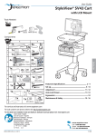
User Guide
StyleView® SV43 Cart
with LCD Arm
Tools Needed
1
14mm (9/16")
2
Components
A
1
B
1x
3x
4x
12x
2
1x
3
1x
1x
2x
M4 x 5mm
2x
4x
ENGLISH
M4 x 10mm
4
M4 x 10mm
8x
1x
2x
5
1x
M3.5 x 6mm
4x
1x
1x
1x
1x
6
M4 x 8mm
7
8
5mm
1x
1x
3mm
1x
1x
1x
9
1x
2x
1x
M4 x 8mm
Features & Specifications ............................................... 2 - 4
Set-up ............................................................................ 5 - 14
Adjustment ................................................................. 11 - 12
Auto-Lock Drawer ....................................................... 13 - 14
Ergonomics .........................................................................14
Maintenance & Safety ................................................ 15 - 16
M4 x 12mm
For local customer care phone numbers visit: http://contact.ergotron.com
For the latest User Installation Guide and StyleLink Software Download please visit: www.ergotron.com
User's Guide - English
Guía del usuario - Español
Manuel de l’utilisateur - Français
Gebruikersgids - Deutsch
Benutzerhandbuch - Nederlands
Guida per l’utente - Italiano
Användarhandbok - svenska
ユーザーガイド : 日本語
用户指南 : 汉语
888-24-299-G-00 rev. B • 10/14
1/16
Features & Specifications
1
2
9
15
14
5
4
8
3/10
7
6
11
15
13
2a
16
12
ENGLISH
1. Height Adjustable LCD Mount attaches LCDs or tablet PC's with 75x75 or 100x100mm mounting
interface
2. Worksurface 2a. Worksurface Lock and Release
3. Secure Storage for Laptop, Thin Client or CPU
4. Front Handle
5. Height Adjustment Brake Handle
6. USB Hub connects keyboard and mouse USB cables
7. Keyboard tray slides out, tilts and allows for right or left mousing with attached mouse holder
8. Keyboard Light under Front Handle
9. Keyboard Light Switch
10. Cable Management and Storage for excess cables and power supplies
11. Storage Basket and Rear Handle
12. Front Locking Casters
13. Quick Reference Card
14. Scanner Holder
15. Antimicrobial worksurface and antimicrobial coating on wrist rest
16. Auto-Lock Drawer (see page 3 for drawer configurations)
WARNING
AVERTISSEMENT
14mm (9/16”)
10 °C
50 °F
IMPACT HAZARD!
MOVING PARTS CAN CRUSH AND CUT.
Failure to heed this warning may result in serious personal
injury or property damage!
Minimize Lift Tension BEFORE:
Removing Mounted Equipment, Shipping Cart, Storing Cart.
DANGER D’IMPACT !
LES PARTIES EN MOUVEMENT PEUVENT ÉCRASER ET COUPER.
Il existe un risque de blessure corporelle ou d’endommagement
matériel en cas de non respect de cet avertissement.
Minimisez la tension d’élévation AVANT :
de retirer l’équipement fixé, d’expédier le chariot, de stocker le chariot
www.ergotron.com
29 °C
86 °F
-20 °C
- 4 °F
50 °C
122 °F
Relative
Humidity 5-95% rH
Range
Relative
Humidity 5-95% rH
Range
Operational
Storage
CAUTION: Close worksurface before opening drawers. Open
only one drawer at a time. Do Not push cart when drawers or
worksurface are open. Failure to follow these instructions may
cause the cart to be unstable.
This Class A digital apparatus complies with Canadian ICES-003.
Cet appareil numérique de la classe A est conforme à la norme NMB-003 du Canada.
FCC Compliance Statement
The cart has been tested and found to comply with the limits for a Class A digital device, pursuant to part 15 of the FCC Rules.
These limits are designed to provide reasonable protection against harmful interference when the equipment is operated in
a commercial environment. This equipment generates, uses, and can radiate radio frequency energy and, if not installed and
used in accordance with the instruction manual, may cause harmful interference to radio communications. Operation of this
equipment in a residential area is likely to cause harmful interference in which case the user will be required to correct the
interference at his own expense.
Changes or modifications not expressly approved by Ergotron, Inc. could void the user’s authority to operate the
equipment.
Please contact Ergotron for complete EMC compatibility information.
826-501
IMPORTANT! This product will need tension adjustments once installation is complete. Make sure all equipment is properly installed on the product before
attempting range of motion or tension adjustments. Any time equipment is added or changed on this product resulting in a different mounted weight, you
should repeat the adjustment steps to ensure safe and optimum operation. This product should move smoothly and easily through the full range of motion and
stay where you set it. If movement is difficult or the product does not stay where you set it, follow the adjustment instructions to loosen or tighten the tension
to create a smooth, easy motion. Depending on your product and the adjustment, it may take many turns to notice a difference.
2/16
888-24-299-G-00 rev. B • 10/14
Features & Specifications
Part Number
Auto-Lock Drawer
SV43-1210-0
1 Drawer*/16 compartments
SV43-1220-0
2 Drawers*/32 compartments
SV43-1240-0
4 Drawers*/28 compartments
SV43-1260-0
6 Drawers*/24 compartments
SV43-1290-0
9 Drawers*/36 compartments
*Auto-Lock Drawer
1 Drawer
2 Drawers
2.5"
(64 mm)
4 Drawers
6 Drawers
9 Drawers
10.5"
10.5"
(267 mm)
(267 mm)
3.75"
12.5"
(96 mm)
(315 mm)
<14 lbs (6.4 kg)
7"
(178 mm)
0 lbs (0 kg) Open Worksurface
<5 lbs (2.3 kg) Closed Worksurface
<13 lbs (5.9 kg) CPU Compartment
60˚
20"
5˚
(508 mm)
12˚
<2 lbs (0.9 kg)
see inset, below
*Combined LCD and CPU Compartment weight:
<27 lbs (12.2 kg).
180˚
CAUTION:
If the combined LCD and CPU weight is greater than 27 lbs (12.2 kg) then the CPU must be
mounted to the rear of the cart using the Universal CPU Holder accessory (ordered separately).
180˚
Total weight capacity per drawer.
< 2 lbs (1 kg)
888-24-299-G-00 rev. B • 10/14
<0.25 lbs (0.1 kg)
Total weight capacity per
drawer.
3/16
ENGLISH
Weight Capacity
Features & Specifications
19.5"
(495 mm)
4" - 11"
17"
(102-279 mm)
(432 mm)
13.4"
50.5"
3.27"
(1282 mm)
(83 mm)
(340 mm)
3.4"
(86 mm)
7.4"
(188 mm)
40"
(1016 mm)
31"
(787 mm)
8.5"
(216 mm)
31" - 51"
2.5"
15.4"
(787-1295 mm)
(64 mm)
(390 mm)
3.7"
(95 mm)
17.5"
23" - 43"
19.75"
(502 mm)
(445 mm)
7"- 8.5"
(178-216 mm)
(584-1092 mm)
16.75"
(425 mm)
19.25"
(489 mm)
22.38"
12.4"
(315 mm)
2" (51 mm)
21"
(568 mm)
4"
(102 mm)
(533 mm)
CPU Compartment
**< 4"
*
(102 mm)
*< 17.63"
**< 2.75"
(448 mm)
(70 mm)
< 2.3"
(58 mm)
ENGLISH
< 4" (102 mm)
< 12.25"
Front View
< 2.75" (70 mm)
< 1.38"
**< 8"
(35 mm)
(203 mm)
(311 mm)
< 12.25"
*< 21.75"
**< 7.75"
(197 mm)
(552 mm)
(311 mm)
When figuring dimensions,
include mounted accessories,
protruding cables and
port replicators or docking
stations.
< 14.75" (375 mm)**
**< 2.75"
(70 mm)
*< 17.75"
(451 mm)
**< 4.25"
(108 mm)
< 13"
Side View
(330 mm)
Top View
4/16
888-24-299-G-00 rev. B • 10/14
Set-up
1
Release Brake to move riser.
2a
40"
(1016 mm)
2
1
2x
M3.5 x 6mm
b
1x
888-24-299-G-00 rev. B • 10/14
1x
5/16
ENGLISH
CAUTION! Completely release brake
engagement before raising or lowering
the cart. Raising or lowering the cart with
the brake partially engaged may cause
product damage.
Set-up
3a
1x
1x
b
1x
ENGLISH
1x
c
1x
6/16
888-24-299-G-00 rev. B • 10/14
Set-up
4a
b
c
Connect Keyboard and Mouse to USB Hub
USB (Type A)
ENGLISH
USB (Type A)
NOTE: Bar Code Scanner should be connected directly to
computer USB port.
DO NOT connect Bar Code Scanner to the USB Hub.
5a
0˚
0˚
1x
b
M4 x 5mm
75x75mm / 100x100mm
WARNING
Impact Hazard!
Moving Parts can Crush and Cut.
4x
M4 x 10mm
Raise monitor to top of vertical
adjustment BEFORE removing.
Failure to heed this warning
may result in serious personal
injury or property damage!
822-311
888-24-299-G-00 rev. B • 10/14
7/16
Set-up
6
To increase space and improve airflow, power brick may be stored under the storage area.
1x
2x
M4 x 12mm
b
2x
a
ENGLISH
d
c
Route power cable down along tower.
1x
1x
WARNING
DO NOT OPERATE
WITHOUT
GUARD
IN PLACE
8/16
WARNING! DO NOT OPERATE WITHOUT GUARD IN PLACE. Only
remove guard when routing a cable with a large connector through
the bottom of the compartment. Replace guard imediately after
routing cable. Failure to replace guard my result in equipment
damage and or personal injury.
822-447-00
888-24-299-G-00 rev. B • 10/14
Set-up
7
Place computer and AC power adaptors in compartment. Do not place power bricks near
computer or compartment air vents.
a
4x
2x
a 4x
4x
M4 x 10mm
b
1x
c
ENGLISH
b
1x
Plug the following factory connected cables into your computer.
USB: This cable runs from the USB Hub to your computer and uses your computer to power the USB Hub, Keyboard Lights and Fan. (NOTE: Your computer must be turned
on for the USB Hub, Keyboard Lights and Fan to function).
WARNING: Fan must always be running when
computer is on. Operating computer without fan
may lead to overheating, resulting in reduced
equipment performance.
888-24-299-G-00 rev. B • 10/14
9/16
Set-up
d
Placement of CPU's in Secure Storage Area:
USFF (Ultra Small Form Factor)
Thin Client
DO NOT OBSTRUCT AIR VENTS!
Obstructing air vents may cause overheating and result in
equipment damage.
e
Center CPU in storage area.
To increase space and improve airflow,
power brick may be stored under the
storage area.
1
2
ENGLISH
If computer with cables is too wide, then
follow these instructions.
f
1x
8
10/16
888-24-299-G-00 rev. B • 10/14
Adjustment
9
a
It is important that you adjust this product according to the weight of the mounted equipment as described in the following steps. Any time equipment is added or removed from this
product, resulting in a change in the weight of the mounted load, you should repeat these adjustment steps to ensure safe and optimum operation.
Adjustments should move smoothly and easily through the full range of motion and stay where you set it. If adjustments are difficult and do not stay in the desired position, follow
the instructions to loosen or tighten the tension to create a smooth, easy adjustment motion. Depending on your product and the adjustment, it may take several turns to notice a
difference.
Lift – Up and down
Release Brake to move riser.
Follow these instructions to tighten or loosen tension.
1x
14mm (9/16")
b
Tilt – Forward and Backward
ENGLISH
M4 x 8mm
NOTE: Adjustment
may require 40 - 60
revolutions.
Follow these instructions to tighten or loosen tension.
3mm
888-24-299-G-00 rev. B • 10/14
11/16
Adjustment
c
Lift – Up and down
Follow these instructions to tighten or loosen tension.
5mm
d
Pan – Side-to-side
Follow these instructions to tighten or loosen tension.
3mm
ENGLISH
Set-up
10
12/16
888-24-299-G-00 rev. B • 10/14
Auto-Lock Drawer
11
AutoLock Drawer Battery Pack
6x
CAUTION! Only use NiMh rechargeable batteries. Using nonrechargeable batteries may cause product damage.
AA
Rechargeable
Nickel Metal
Hydride
USB to
computer.
Batteries may not come fully charged and may need to charge for several hours. To charge ALD
batteries computer needs to be powered on and connected to the USB hub.
USB to charge ALD
batteries.
1x
CAUTION: Open only one drawer at a time. Do Not push cart when drawers
are open. Failure to follow these instructions may cause the cart to be
unstable.
NOTE: User should change Master Personal Identification Number (PIN) upon receipt of cart.
Lost Master PIN
Contact Ergotron Customer Care for instructions.
ENGLISH
All PINs may vary in length from 4 – 7 digits. Number of PINs possible:
- Carts using StyleLink will store up to 1,000 PINs on the cart
- Carts not using StyleLink will store up to 100 PINs on the cart
- Ergotron recommends the following for choosing PIN digit length (assumes less than 1 in 25 chance of guessing random User PIN):
Max number of User PINs >50, 5+digit length recommended
Max number of User PINs >300, 6+digit length recommended
For maximum security use PIN length of 7
Set-up Master PIN for the First Time (Default Master PIN: 12345)
Contact Ergotron Customer Care for instructions if Master PIN is lost.
1. Enter default Master PIN (1-2-3-4-5) then press ENTER.
2. Press 5 for Master PIN Entry mode
3. Enter new Master PIN and press Enter (LEDs will blink green if PIN is accepted)
4. Master PIN entry mode will exit after 5 seconds of inactivity (LEDs blink red twice)
Master PIN Mode Menu
Enter Master PIN and then select one of the below numbers to enter that mode
1. User PIN Entry Mode
2. Pharmacy PIN Entry/Change Mode
5. Master Pin Change Mode
Programming User PINS
1. Enter Master PIN and press ENTER for Mode Menu.
2. Press 1 for User PIN Entry Mode.
3. Input new User PIN and press ENTER (All LEDs blink green if PIN is accepted). You may enter multiple USER PINs consecutively.
4. User PIN entry mode will exit after 5 seconds of inactivity (LEDs blink red twice).
NOTE: User PIN cannot be the same as a Master PIN or Pharmacy PIN. Once maximum User PIN storage is exceeded, the oldest User PIN will be over written.
Programming Pharmacy PIN
1. Enter Master PIN and press ENTER for Mode Menu
2. Press 2 for Pharmacy PIN Entry Mode
3. Input Pharmacy PIN and press ENTER (all LEDs blink green in PIN is accepted).
4. Pharmacy PIN entry mode will exit after 5 seconds of inactivity (LEDs blink
red twice).
888-24-299-G-00 rev. B • 10/14
Note: System will hold 1 Pharmacy PIN. Pharmacy PIN allows all drawers to unlock at the
same time. Drawers should then be opened at least slightly as the system will auto-lock after
10 seconds. All LEDs will flash green until system auto-locks. Once a drawer is opened the
corresponding LED for that row will light solid until it is placed back into its original location.
13/16
Auto-Lock Drawer
Unlock Drawer (2 methods): NOTE: All Drawers in row must be closed before a new row can be unlocked.
• Enter User PIN (only numbers for available drawer rows flash green), then press desired drawer row number*.
• Key - turn clockwise 1/4 turn
*Drawer Row Numbers:
1
1
1
1
2
2
1
2
2
3
Lock Drawer:
• Wait 4 seconds for lock to engage automatically.
NOTE: Always ensure drawer is pushed in all the way and engaged with lock.
Drawer Troubleshooting
• No LEDs on keypad when pressing any number:
•Verify battery box is connected to controller.
• Verify keypad cable is connected to controller.
• Verify battery box switch is in the ON position and that batteries are
properly installed.
• Drawer selection not available when User PIN is entered:
• Check to make sure drawer cable is installed securely.
• Remove power from drawer system for 10 seconds and re-apply.
• LEDs flash red/green after User PIN in entered:
• Battery charge is low, check to make sure USB charging cable is
plugged into computer and computer is ON.
LEDs/Alarm Meaning:
1,2,3,4, or 5 LED ON green: Corresponding Drawer is open.
1,2,3,4, or 5 LED flashing red and alarm sounding: Corresponding Drawer is open longer than 20
seconds. Mute alarm by pressing flashing button corresponding to open drawer.
All available drawer numbers flashing green: Waiting for drawer selection (see Unlock Drawer).
All LEDs flashing green: Pharmacy mode, all drawers are unlocked.
All LEDs blink red twice: PIN entry rejected/exit current mode after 5 seconds timeout.
All LEDs blink green 3 times: PIN entry accepted.
All LEDs flashing red: Firmware update in progress.
All LEDs flashing red/green: System power ON or low battery condition.
ENGLISH
Adjustment
12
Keyboard Light
1. Turn Computer on.
2. Test Keyboard Light.
Keyboard Light will automatically turn off after 15 minutes if not
manually turned off.
Ergonomics
Working
Moving
customize - to your size
stow - before you go
1 Set top of monitor screen about one inch below eye level - Release brake and lift or lower riser
as needed.
1 During normal movement, release brake and lower worksurface to lowest
position for optimal stability and unobstructed view.
2 Tilt screen for comfortable viewing and to reduce eye and neck strain.
2 Tuck away open trays and return mouse, scanner and other accessories
to their places.
3 Pull keyboard tray forward and position mouse tray on right or left, as needed.
3 Unlock both front casters.
4 Work with elbows bent at about 90° to minimize muscle strain.
5 If the riser moves up and down with difficulty, or if it drifts out of set position, consult the product
manual for adjustment information.
6 Stay in charge!
Powered carts should be plugged into outlet as often as possible to keep battery charged and
computer running.
4 Push cart from rear with elbows bent at about 90° to maximize control
and minimize muscle strain.
5 Don’t run out!
Before moving, make sure cord is unplugged from outlet and hooked to
basket for safe travel. Remember, charge battery fully 100% every day!
1
1
2
4
3
5
4
6
5
2
3
14/16
888-24-299-G-00 rev. B • 10/14
Maintenance & Safety
Hazard Symbols Review
The Meaning of Symbols appearing in this Guide, on the
Cart or on the Power System
These symbols alert you to a safety condition that
demands your attention. You should be able to recognize
and understand the significance of the following Safety
Hazards if you encounter them on the Cart or within Cart
documentation such as this Set-up Guide.
Symbol
Signal Word/
Color
DANGER
Level of Hazard
Indicates an imminently hazardous situation which, if not
avoided, will result in death or serious injury.
WARNING
Indicates a potentially hazardous situation which, if not
avoided, could result in death or serious injury.
CAUTION
Indicates a potentially hazardous situation which, if not
avoided, may result in minor or moderate injury.
CAUTION
Used without the safety alert symbol indicates a potentially
hazardous situation which, if not avoided, may result in
property damage.
INSTRUCTIONS
Follow operating instructions.
INSTRUCTIONS
Follow operating instructions.
EQUIPMENT & ACCESSORIES DISPOSAL
1. Please dispose of all batteries in accordance with local
law
2. All Electronics should be recycled through an
electronics recycler.
3. Remaining plastics and metals can be recycled
through a commercial recycler.
POWER
"ON" / "OFF" (push-push)
NOTE: Each position "ON" / "OFF" is a stable position.
To avoid risk of electric shock, do not expose electrical components to water, cleaning solutions or other potentially corrosive liquids or substances.
Do not immerse Cart or Cart components in liquid or allow liquids to flow into the Cart. Wipe all cleaners off surface immediately using a damp cloth. Thoroughly dry surface
after cleaning.
Do not use flammable cleaners on Cart surfaces due to close proximity of electrical power and equipment.
All paints and plastic Cart components will withstand cleaning by most commonly used, diluted, non-abrasive solutions such as quaternary ammonia compounds, ammonia
enzyme cleaners, bleach or alcohol solutions.
• Pen and permanent and dry erase markers can be removed with 91% isopropyl alcohol and a soft cloth.
• Iodine stains can be removed with commonly used cleaners and a soft cloth.
• Never use steel wool or other abrasive materials that will damage the surface finish.
• Do not use strong solvents such as trichloroethylene and acetone. These solvents will damage the surface finish.
It is recommended that any cleaning solution be tested on a small, inconspicuous area to ensure surface is not harmed.
Adjustment, Service, Replacement - DO NOT attempt to adjust, service or replace any part of the StyleView Cart unless directed to do so through Ergotron-approved
documentation (i.e. installation instructions). Only Ergotron, Inc. or an Ergotron-certified entity may adjust, service or replace StyleView Cart components. If any component on the
Cart is missing or damaged, the Cart must not be used, contact Ergotron Customer Care immediately to request a replacement part.
Cables - Keep cables neatly organized on the Cart (a variety of solutions are provided with your cart for this purpose). Excess cables should be routed away from moving
components with cable clips. Review Cable Routing section of this guide, or contact Ergotron Customer Care for more information.
Casters - Check casters periodically to make sure they are clean and free of debris that would prevent smooth travel. Avoid moving Cart across uneven, dirty or damaged
surfaces.
Customer Equipment- Make sure equipment is balanced and mounted securely to Cart. Do not reposition Cart components on riser or tower unless instructed to do so in the
installation instructions. Moving Cart components too high or too low on the Riser may create an unstable condition, leading to equipment damage or even personal injury. Contact
Ergotron Customer Care for information about moving Cart components.
888-24-299-G-00 rev. B • 10/14
15/16
ENGLISH
Cleaning and Maintenance
The following procedures are not guaranteed to control infection. The hospital infection control administrator or epidemiologist should be consulted regarding cleaning procedures
and processes.
Maintenance & Safety
Safety Alerts Associated with this Product
The following Warnings/Cautions appear in this reference guide or on the cart:
NOTE: Failure to adhere to these guidelines may result in equipment damage or personal injury.
CAUTION: The lift brake helps stablilize the worksurface and keyboard tray during normal use but it DOES NOT increase load capacity. DO NOT load riser with equipment
totaling more than the maximum weight capacity specified by Ergotron. Ensure optimum lift function by testing and if necessary, re-adjusting tension whenever the weight
mounted to the riser changes (i.e., equipment is removed or added). See "Set Riser Lift Tension" adjustment instructions.
CAUTION: Do not operate StyleView Cart with missing or damaged components! Do not remove, modify or substitute Cart components without consulting Ergotron. If you
encounter problems with Cart installation or operation, contact Ergotron Customer Care.
CAUTION: DO NOT overtighten fasteners. Overtightening may cause damage to your equipment.
WARNING: Stored Energy Hazard: The worksurface lift mechanism is under tension and will move up rapidly, on its own, as soon as attached equipment is removed. For this
reason, DO NOT remove equipment unless the worksurface has been moved to the highest position on the tower! Failure to follow this instruction may result in serious personal
injury and/or equipment damage! When Shipping the cart, set the worksurface lift mechanism to the lowest tension setting.
CAUTION: DO NOT loosen, tighten or remove any other nuts or bolts on the riser or top of tower. Tampering with nuts or bolts may result in an unstable Cart, leading to
equipment damage and/or personal injury.
CAUTION: Release Lift Brake before moving work surface! Moving work surface while Lift Brake is engaged may cause serious damage to Lift Engine.
WARNING: In the event that repair of the StyleView Cart is needed, contact Ergotron Customer Care immediately. Cart repair can only be performed by Ergotron, Inc. or by an
Ergotron authorized agent.
WARNING: This cart is not intended for use in a flammable, anesthetic mixture or oxygen rich environment.
Configuration & Safety
Additional multiple socket-outlet or extension cord shall not be connected to the medical system.
When used in a Medical Electrical system, connect only equipment that complies with IEC, ISO, UL/ANSI, or CSA standards that are relevant to that equipment.
Risk of shock or personal injury when connecting non-medical equipment supplied as part of a system directly to the wall outlet when non-medical equipment is intended to
be supplied by the multiple socket outlet.
ENGLISH
Risk of shock or personal injury when connecting any equipment that has not been supplied as part of the medical system to the multiple socket outlet.
Recommended Periodic Inspection and Maintenance
Component
Action
How often
By whom
UI, Ethernet, USB
cables
Inspect for wear, pinching, bad
connectors
Monthly
Any user
Fan on side of CPU
compartment
Inspect for dust at intake, vacuum
as required using a vacuum cleaner
that DOES NOT generate ESD
(Electrostatic Discharge)
Monthly
Any user
Casters
Inspect for wear and debris
Monthly
Any user
Maximum Load
Inspect to ensure that maximum
recommended loads are not
exceeded
Daily
Any user
1. Please dispose of all batteries in accordance with local law
2. Always replace with similar size battery (33 A-h to replace 33 A-h) and always replace in pairs
16/16
888-24-299-G-00 rev. B • 10/14